Note : Les descriptions sont présentées dans la langue officielle dans laquelle elles ont été soumises.
CA 03202984 2023-05-24
WO 2022/120068 PCT/US2021/061638
NEEDLE TIP BLUNTING
USING A LENGTH OF A GUIDE WIRE
PRIORITY
[0001] This application claims the benefit of priority to U.S.
Provisional Application
No. 63/120,913, filed December 3, 2020, which is incorporated by reference in
its entirety into
this application.
BACKGROUND
[0002] The insertion of intravascular catheters through the skin and into
the vasculature
of a patient generally includes the use of a needle disposed within the lumen
of the catheter.
The needle provides a sharp tip and adds stiffness to the catheter to aid the
insertion process.
Catheters may come packaged with a needle already inserted or the clinician
may insert the
needle into the catheter at the point of use. In some instances, a clinician
may reinsert a needle
into a catheter after initial placement of the catheter. The rapid placement
of larger catheters
such a central venous catheters (CVC) may include inserting an introducer
catheter through a
lumen of the CVC. In such an instance, the introducer catheter may comprise a
needle. The
forgoing are just a few examples of many situations where a clinician may
insert a needle
through a catheter lumen. The tubular portions of the catheters are flexible
and may be several
inches in length. These characteristics pose difficulty when inserting a sharp
needle through
the lumen of the catheter. The insertion of the needle though the lumen of the
catheter can also
potentially pierce the catheter's tubular wall rendering the catheter unfit
for use. As set forth
above, there is a need to reduce the propensity of the needle tip to puncture
a catheter wall upon
insertion of the needle through the lumen of the catheter lumen. Disclosed
herein are needle tip
blunting guidewires and methods thereof that address the foregoing.
SUMMARY
[0003] Disclosed herein are embodiments of a guidewire, including a
flexible distal
section, flexible proximal section, and a middle section disposed between the
distal section and
the proximal section. In some embodiments, the distal section is configured
for insertion into
a vasculature of a patient. In some embodiments, the middle section is less
flexible than the
distal section and the proximal section. The middle section may be stiff and a
diameter of the
middle section may be greater than a diameter of the distal section. In some
embodiments, a
tapered distal transition portion is disposed between the distal section and
the middle section.
-1-
CA 03202984 2023-05-24
WO 2022/120068 PCT/US2021/061638
[0004] In some embodiments, the guidewire comprises a solid core wire
extending a
length of the guidewire. The solid core wire includes a first diameter
extending along the distal
section, a second diameter extending along the proximal section, and a third
diameter extending
along the middle section. The third diameter, which may be greater than the
first diameter and
the second diameter, defines an outside diameter of the guidewire along the
middle section.
[0005] In some embodiments, the guidewire comprises a solid core wire
extending a
length of the guidewire and a coil disposed around the solid core wire along
the length of the
guidewire. The guidewire may further include a material applied around the
guidewire along
the middle section. The material may be a liquid during application and may
transform into a
solid after application.
[0006] In some embodiments, the guidewire comprises a solid core wire
extending a
length of the guidewire and a cannula threaded onto the solid core wire. The
cannula is
positioned along the middle section, and the cannula defines an outside
diameter of the
guidewire along the middle section.
[0007] In some embodiments, the guidewire comprises a flexible distal
section, flexible
proximal section, a stiff middle section disposed between the distal section
and the proximal
section; and a cannula threaded onto the guidewire. A distal tip of the
cannula is positioned so
that a proximal portion of the middle section is disposed within the cannula
and a distal portion
of the middle section extends distally beyond the distal tip of the cannula.
An outside diameter
of the middle section and an inside diameter of the cannula can: 1) define a
longitudinal sliding
fit between the middle section and the cannula, and 2) constrain the middle
section to be parallel
to the cannula.
[0008] In some embodiments, a method of using a guidewire comprises
obtaining a
guidewire including a flexible distal section, a flexible proximal section,
and a stiff middle
section disposed between the distal section and the proximal section;
threading a cannula onto
the guidewire; positioning a tip of the cannula between a distal end and a
proximal end of the
middle section; and inserting the cannula and the guidewire distally through a
tubular member
while maintaining the position of the cannula with respect to the guidewire.
The method may
further comprise contacting the tubular member with the middle section to
constrain the tubular
member away from a sharp point of the cannula.
-2-
CA 03202984 2023-05-24
WO 2022/120068 PCT/US2021/061638
[0009] In some embodiments, at least a portion of the proximal section
may be disposed
within the cannula after positioning the tip of the cannula between the distal
end and the
proximal end of the middle section. In some embodiments, the tubular member is
a first
intravascular catheter which may be at least partially inserted into a
vasculature of a patient. In
some embodiments, the method comprises inserting the guidewire and the cannula
into a
second intravascular catheter. In still other embodiments, the method
comprises inserting the
guidewire, the cannula, and the first intravascular catheter into a second
intravascular catheter.
In some embodiments, the method further comprises inserting the distal section
of the
guidewire into a vasculature and in some embodiments, the distal section is
inserted into the
vasculature before the cannula is threaded onto the guidewire.
[0010] These and other features of the concepts provided herein will
become more
apparent to those of skill in the art in view of the accompanying drawings and
following
description, which describe particular embodiments of such concepts in greater
detail.
DRAWINGS
[0011] FIG. 1 illustrates a needle tip blunting guidewire, in accordance
with some
embodiments.
[0012] FIG. 2 is a cross-sectional side view of a portion of the needle
tip blunting
guidewire of FIG. 1 illustrating a first construction method of the needle tip
blunting guidewire,
in accordance with some embodiments.
[0013] FIG. 3 is a cross-sectional side view of a portion of the needle
tip blunting
guidewire of FIG. 1 illustrating a second construction method of the needle
tip blunting
guidewire, in accordance with some embodiments.
[0014] FIG. 4 is a cross-sectional side view of a portion of the needle
tip blunting
guidewire of FIG. 1 illustrating a third construction method of the needle tip
blunting
guidewire, in accordance with some embodiments.
[0015] FIG. 5 is a cross-sectional side view of a portion of the needle
tip blunting
guidewire of FIG. 1 in combination with a portion of a cannula, in accordance
with some
embodiments.
-3-
CA 03202984 2023-05-24
WO 2022/120068 PCT/US2021/061638
[0016] FIG. 6 is a cross-sectional side view of the combination of FIG. 5
in further
combination with a portion of a tubular member, in accordance with some
embodiments.
DESCRIPTION
[0017] Before some particular embodiments are disclosed in greater
detail, it should be
understood that the particular embodiments disclosed herein do not limit the
scope of the
concepts provided herein. It should also be understood that a particular
embodiment disclosed
herein can have features that can be readily separated from the particular
embodiment and
optionally combined with or substituted for features of any of a number of
other embodiments
disclosed herein.
[0018] Regarding terms used herein, it should also be understood the
terms are for the
purpose of describing some particular embodiments, and the terms do not limit
the scope of the
concepts provided herein. Ordinal numbers (e.g., first, second, third, etc.)
are generally used to
distinguish or identify different features or steps in a group of features or
steps, and do not
supply a serial or numerical limitation. For example, "first," "second," and
"third" features or
steps need not necessarily appear in that order, and the particular
embodiments including such
features or steps need not necessarily be limited to the three features or
steps. Labels such as
"left," "right," "top," "bottom," "front," "back," and the like are used for
convenience and are
not intended to imply, for example, any particular fixed location,
orientation, or direction.
Instead, such labels are used to reflect, for example, relative location,
orientation, or directions.
Singular forms of "a," "an," and "the" include plural references unless the
context clearly
dictates otherwise.
[0019] With respect to "proximal," a "proximal portion" or a "proximal
end portion"
of, for example, a catheter disclosed herein includes a portion of the
catheter intended to be
near a clinician when the catheter is used on a patient. Likewise, a "proximal
length" of, for
example, the catheter includes a length of the catheter intended to be near
the clinician when
the catheter is used on the patient. A "proximal end" of, for example, the
catheter includes an
end of the catheter intended to be near the clinician when the catheter is
used on the patient.
The proximal portion, the proximal end portion, or the proximal length of the
catheter can
include the proximal end of the catheter; however, the proximal portion, the
proximal end
portion, or the proximal length of the catheter need not include the proximal
end of the catheter.
That is, unless context suggests otherwise, the proximal portion, the proximal
end portion, or
the proximal length of the catheter is not a terminal portion or terminal
length of the catheter.
-4-
CA 03202984 2023-05-24
WO 2022/120068 PCT/US2021/061638
[0020] With respect to "distal," a "distal portion" or a "distal end
portion" of, for
example, a catheter disclosed herein includes a portion of the catheter
intended to be near or in
a patient when the catheter is used on the patient. Likewise, a "distal
length" of, for example,
the catheter includes a length of the catheter intended to be near or in the
patient when the
catheter is used on the patient. A "distal end" of, for example, the catheter
includes an end of
the catheter intended to be near or in the patient when the catheter is used
on the patient. The
distal portion, the distal end portion, or the distal length of the catheter
can include the distal
end of the catheter; however, the distal portion, the distal end portion, or
the distal length of
the catheter need not include the distal end of the catheter. That is, unless
context suggests
otherwise, the distal portion, the distal end portion, or the distal length of
the catheter is not a
terminal portion or terminal length of the catheter.
[0021] Unless defined otherwise, all technical and scientific terms used
herein have the
same meaning as commonly understood by those of ordinary skill in the art.
[0022] Any methods disclosed herein include one or more steps or actions
for
performing the described method. The method steps and/or actions may be
interchanged with
one another. In other words, unless a specific order of steps or actions is
required for proper
operation of the embodiment, the order and/or use of specific steps and/or
actions may be
modified. Moreover, sub-routines or only a portion of a method described
herein may be a
separate method within the scope of this disclosure. Stated otherwise, some
methods may
include only a portion of the steps described in a more detailed method.
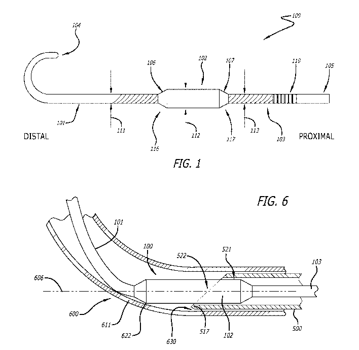
[0023] FIG. 1 illustrates a needle tip blunting guidewire (NTBG) 100, in
accordance
with some embodiments described herein. The NTBG 100 may be used in
conjunction with a
needle cannula to blunt a sharp tip of the cannula as described in detail
below. The NTBG 100
may be configured to be inserted through a cannula. The NTBG 100 includes a
distal section
101, a middle section 102, a proximal section 103, a distal end 104, and a
proximal end 105.
Each of the sections 101, 102, and 103 may include different dimensions and
properties as
further described. The middle section 102 includes a distal end 116 and a
proximal end 117.
[0024] The distal section 101 may be configured to be disposed within a
vasculature of
a patient. As such, the distal section 101 may comprise a flexibility
sufficient to traverse a
vasculature without causing injury to the vascular wall. In other words, the
distal section 101
may flex during insertion to conform with the vasculature structure without
kinking or
-5-
CA 03202984 2023-05-24
WO 2022/120068 PCT/US2021/061638
plastically deforming. In some embodiments, the distal section 101 may
comprise a flexibility
that is consistent with medical guidewires configured to traverse a
vasculature, as discussed
further below. The distal section 101 may also comprise sufficient stiffness
to facilitate
insertion via a distally applied compression force without buckling within the
vasculature. In
some embodiments, the distal section 101 may include a length sufficient to
extend from the
vasculature insertion site to a desired location within the vasculature such
as a location near or
within the heart. As such, placement of intravascular devices may include use
of the NTBG
100 as an intravascular guidewire. In other embodiments, the distal section
101 may be short,
such that the distal section extends less than about 1 to 5 centimeters away
from a cannula tip,
for example.
[0025] The distal section 101 may comprise a round cross section having a
diameter
111 consistent with insertion through the vasculature, a cannula and/or a
catheter lumen. In
some embodiments, the distal section 101 may comprise one or multiple
preformed curves or
shapes to aid insertion through the vasculature. Preformed shapes may be two-
dimensional,
such as the "J" shape illustrated in FIG. 1, or three-dimensional.
[0026] The proximal section 103 may be configured to be manually inserted
into a
cannula of a needle. The proximal section 103 may comprise adequate stiffness
to facilitate
being manually grasped by a clinician and urged distally into the cannula
without kinking or
plastically deforming. The proximal section 103 may comprise a flexibility
consistent with
being coiled for placement in a package container without kinking or
plastically deforming. In
some embodiments, the proximal section 103 may be less flexible than the
distal section 101.
The proximal section 103 may comprise a round cross section having a diameter
113 consistent
with disposition within the cannula. In some embodiments, the diameter 113 may
be larger
than the diameter 111. In some embodiments, the proximal section 103 may be
configured to
be disposed within the vasculature of a patient and therefore, the proximal
section 103 may
comprise similar physical properties as the distal section 101.
[0027] In some embodiments, the proximal section 103 may include indicia
110. The
indicia 110 may be indicative of a distance to the middle section 102. In some
instances, the
distal tip of the cannula may not be visible to a clinician. A location of
indicia 110 with respect
to a proximal end of the cannula may indicate a position of the middle section
102 with respect
to a distal tip of the cannula. The indicia 110 may also be indicative of a
distance to the distal
-6-
CA 03202984 2023-05-24
WO 2022/120068 PCT/US2021/061638
end 104 of the NTBG 100. In some instances, a clinician may observe the
indicia 110 to
determine the position of the distal end 104 along the vasculature of the
patient.
[0028] The middle section 102 is disposed between the distal section 101
and the
proximal section 103. In the illustrated embodiment, the middle section 102
may be straight to
correspond with a straight cannula. In some embodiments, the middle section
102 may
comprise a curve to correspond with a curved cannula. The middle section 102
may remain
straight during use. As is known, catheters, guidewires and other elongated
medical devices
have varying levels or degrees of stiffness (or flexibility), which is often
referred to as flexural
stiffness or flexural rigidity. Flexural stiffness is understood as the
product of the elastic
modulus (E) of a material and the area moment of inertia (I) where the
flexural stiffness (El)
has the SI units of Newtons (N) meters2 (m2) or N=m2.
[0029] In certain situations, a particular medical procedure may require
a medical
device have a particular degree of stiffness. As is further known, the degree
of stiffness of a
medical device may be determined by the materials from which it is comprised,
the shape and
dimensions of the medical device, and any braiding utilized in its
construction. The middle
section 102 may comprise a round cross section having a diameter 112 that, in
some
embodiments, may be larger than the diameter 111 of the distal section 101 and
the proximal
section 103. The middle section 102 may include a tight diametral tolerance.
In some
embodiments, the diametral tolerance of the diameter 112 may be about 0.002
inches, 0.001
inches, 0.0005 inches, 0.0002 inches, or tighter.
[0030] The middle section 102 may comprise a distal transition portion
106. The distal
transition portion 106 may define a smooth transition of physical properties
between the distal
section 101 and the middle section 102. The distal transition portion 106 may
comprise a taper
to transition the diameter 111 of the distal section 101 to the diameter 112
of the middle section
102. The distal transition portion 106 may also be constructed to transition
the flexibility of the
distal section 101 to the stiffness of the middle section 102. In some
embodiments, the distal
transition portion 106 may define a strain relief In a similar fashion, the
middle section 102
may comprise a proximal transition portion 107. The proximal transition
portion 107 may
define a smooth transition of physical properties between the proximal section
103 and the
middle section 102. In some embodiments, the middle section 102 may be
configured to be
disposed within the vasculature of a patient. More specifically, the length of
the middle section
102 may be sufficiently short to traverse curved portions of an intended
vasculature.
-7-
CA 03202984 2023-05-24
WO 2022/120068 PCT/US2021/061638
[0031] FIGS. 2-4 illustrate different methods of constructing the NTBG
100. As shown
in FIG. 2 according a first construction method, the NTBG 100 may be
constructed of a wire
200 having a solid core. The wire 200 may extend the entire length of the NTBG
100. In some
embodiments, the wire 200 may be formed of a nitinol material. In the
embodiment of FIG. 2,
the wire 200 includes a distal wire portion 201, a middle wire portion 202,
and a proximal wire
portion 203 that correspond with the distal, middle, and proximal sections
101, 102, 103,
respectively. A diameter of the wire 200 may be sufficiently thin along the
distal wire portion
201 and the proximal wire portion 203 to facilitate the flexibility of the
distal and proximal
sections 101, 103, respectively. The distal wire portion 201 and the proximal
wire portion 203
may also be wrapped with the distal coil 210 and the proximal coil 211,
respectively. A
diameter of the wire 200 along the middle wire portion 202 may be sufficiently
thick to
facilitate the stiffness of the middle section 102. The middle wire portion
202 may define the
diameter 112 of the middle section 102. The middle wire portion 202 may also
be formed via
a process consistent with defining the diametral tolerance of the middle
section 102, such as
grinding, for example. In some embodiments, the wire 200 may include a distal
taper 206 to
transition the diameter of the middle portion 202 to the diameter of the
distal wire portion 201
which may at least partially define the transition portion 106. Similarly, the
wire 200 may
include a proximal taper 207 to transition the diameter of the middle portion
202 to the diameter
of the proximal wire portion 201 which may at least partially define the
transition portion 107.
[0032] FIG. 3 illustrates a second construction method of the NTBG 100.
The second
construction method of the NTBG 100 includes a wire 300 having a solid core
extending the
length of the NTBG 100. The wire 300 may be formed of nitinol. In some
embodiments, a
diameter of the wire may be constant along the length of the wire 300, and the
wire 300 may
be wrapped with a coil 310 along the length of the wire 300. The middle
section 102 of the
NTBG 100 is formed by applying a material 320 around the wire 300 and the coil
310 along a
middle portion of the wire 300. The applied material 320 may be a potting or
casting material
such as an epoxy. In some embodiments, the material 320 may be a thermoplastic
material that
is insert molded onto the wire 300 and coil 310. The material 320 may fill in
gaps between
coils 310 which may alter the flexibility of the wire 300 and coil 310. The
material 320 may
add to the diameter of the coil 310 to define the diameter 112 of the middle
section 102. The
material 320 may be a liquid when applied and may transform into a solid after
application.
Once hardened, the material 320 may define the desired stiffness of the middle
section 102.
After hardening, the material 320 may be formed via a process consistent with
defining the
-8-
CA 03202984 2023-05-24
WO 2022/120068 PCT/US2021/061638
diametral tolerance of the of the diameter 112 of middle section 102, such as
grinding, for
example. The material 320 may include a distal taper 326 to transition the
diameter of the
middle section 102 to the diameter of the distal section 101 which may at
least partially define
the transition portion 106. Similarly, the material 320 may include a proximal
taper 327 to
transition the diameter of the middle portion 102 to the diameter of the
proximal section 103
which may at least partially define the transition portion 107.
[0033] FIG. 4 illustrates a third construction method of the NTBG 100.
The third
construction method of the NTBG 100 includes a wire 400 having a solid core
extending the
length of the NTBG 100. The wire 400 may be formed of nitinol. In some
embodiments, a
diameter of the wire may be constant along the length of the wire 400. A
cannula 420 may be
threaded onto the wire 400 and attached to the wire 400. The wire 400 may be
wrapped along
the distal section 101 and the proximal section 103 with distal coil 410 and
proximal 411,
respectively. The middle section 102 of the NTBG 100 is defined by the cannula
420. The
cannula portion 420 may be formed of a metal or a rigid plastic to define the
desired stiffness
of the middle section 102. The cannula 420 may also be formed of a process
consistent with
defining the diametral tolerance of the diameter 112 of the middle section
102, such as grinding,
for example. The cannula 420 may include a distal taper 426 to transition the
diameter of the
middle section 102 to the diameter of the distal section 101 which may at
least partially define
the transition portion 106. Similarly, the cannula 420 may include a proximal
taper 427 to
transition the diameter of the middle section 102 to the diameter of the
proximal section 103
which may at least partially define the transition portion 107.
[0034] FIG. 5 illustrates the NTBG 100 in use with a cannula 500. FIG. 5
shows a
portion of the cannula 500 threaded onto the NTBG 100. In some embodiments,
the NTBG
100 may be provided with a cannula 500. The cannula 500 includes an inside
diameter 511 and
an outside diameter 512. The cannula 500 is threaded onto the proximal section
103, so that a
tip 510 of the cannula 500 is disposed along the middle section 102. The
inside diameter 511
of the cannula 500 is sized to correspond with the diameter 112 of the middle
section 102. More
specifically, the inside diameter 511 and the diameter 112 are sized, so that
a diametral
clearance 513 between the cannula 500 and the middle section 102 is minimized
while allowing
longitudinal sliding motion of the cannula 500 with respect to the middle
section 102. In some
embodiments, the diametral clearance may be less than about 0.003 inches,
0.002 inches, 0.001
inches, 0.0005 inches, or less.
-9-
CA 03202984 2023-05-24
WO 2022/120068 PCT/US2021/061638
[0035] As shown in FIG. 5, the middle section 102 is positioned relative
to the cannula
500, so that a proximal portion 521 of the middle section 102 is disposed
within the cannula
500 and a distal portion 522 extends distally away from the tip 510 of the
cannula 500. The
proximal portion 521 may include a sufficient length, so that in combination
with the clearance
513, the distal portion 522 is constrained to be parallel with the cannula
500. Lengths of the
middle section 102, the proximal portion 521, and the distal portion 522 may
be defined in
relation to the diameter 112 of the middle section 102. In some embodiments,
the length of the
proximal portion 521 may be about 1, 2, 3, 4 or more times the diameter 112 of
middle section
102. In some embodiments, the length of the distal portion 521 may be about
0.25, 0.5, 1, 2, or
more times the diameter 112. In some embodiments, a length of the middle
section 102 may
be about 1.25, 1.5, 2, 3, 4 or more times the diameter 112.
[0036] The tip 510 of the cannula 500 may be a sharp tip such as a tip
consistent with
piercing skin and/or a vascular wall. In other embodiments, the tip 510 may be
a configured
insertion through a septum. In some embodiments, the tip 510 may include a
sharp point 517
disposed on the outside surface 518 of the cannula 500. In other embodiments,
the tip 510 may
include a facet 516 that is cut to displace the point 517 inward away from the
outside surface
518 of the cannula 500.
[0037] The NTBG 100 may be provided in multiple configurations. For
example, in
some embodiment configurations, the distal section 101 may include a length
consistent with
placement of an intravascular device. Similarly, configurations of NTBG 100
may be sized for
use with specific cannula gauges. For example, an embodiment of the NTBG 100
may be
configured for use with a variety of cannulas of a specified gauge. As may be
appreciated by
one of ordinary skill, configurations of NTBG 100 may be provided with any
combination of
physical properties for each of the distal, middle, and proximal sections
(101, 102, 103), such
as length, diameter, and flexibility.
[0038] FIG. 6 illustrates the combination of the NTBG 100 and the cannula
500 of FIG.
in further use with a tubular member 600. In some embodiments, the tubular
member 600
may be an intravascular catheter. As shown in FIG. 6, the longitudinal
position of the middle
section 102 with respect to the cannula 500 is the same as illustrated in FIG.
5. Also as
described above with reference to FIG. 5, the distal portion 522 extends
distally away from the
tip 510 and is constrained to be parallel with the cannula 500. FIG. 6
illustrates the combination
of FIG. 5 inserted into the tubular member 600. The NTBG 100 and the cannula
500 are
-10-
CA 03202984 2023-05-24
WO 2022/120068 PCT/US2021/061638
inserted into the tubular member 600 so that the cannula tip 510 and the
distal portion 522 of
the middle section 102 are disposed within the tubular member 600. The tubular
member 600
is shown in a curved state with the tubular member 600 curving away from a
longitudinal axis
606 of the middle section 102.
[0039] FIG. 6 illustrates an instance, wherein the curve of the tubular
member 600 is
sufficiently sharp to cause a tubular wall 611 of the tubular member 600 to
contact the distal
portion 522 at a contact point 622. As the distal portion 522 is a stiff
extension of the cannula
500, the contact between the tubular wall 611 and the distal portion 522
limits the sharpness of
the curve along a section of the tubular member 600 extending between the
contact point 622
and the cannula 500. Limiting the sharpness of the curve ensures a separation
distance 630
between the point 517 of the cannula tip 510 and the tubular wall 611. The
separation distance
630 in turn ensures that the point 517 does not contact or pierce the tubular
wall 611. By way
of summary, the distal potion 522 of the middle section 102 prevents the tip
510 of the cannula
500 from piercing the tubular member 600. In other words, the sharp tip 510 of
the cannula
500 is converted into a blunt tip by the distal portion 522 of the middle
section 102, protecting
the tubular member 600 from being pierced by the point 517. Therefore, by
first inserting the
NTBG 100 into a cannula 500, a clinician may insert the cannula 500 into a
tubular member
600 without concern for piercing the tubular member 600.
[0040] In some instances, the tubular member 600 may comprise flexibility
and
stiffness characteristics to cause a curvature of the tubular member 600 to
extend proximally
beyond the catheter tip 510 when the tubular wall 611 is in contact with the
distal portion 522
at the contact point 622. In this instance, the curvature of the tubular
member 600 may displace
the tubular wall 611 radially away from the outside surface 518 of the cannula
500 which may
at least partially define the separation distance 630. In such an instance,
piercing of the tubular
member 600 may be prevented in the event that the tip 517 is disposed on the
outside surface
518 of the cannula 500.
[0041] Methods of use of the NTBG may include the following steps or
processes. A
method may include a step of inserting the NTBG through the cannula. The NTBG
may be
inserted distally, i.e., inserting the distal end first, or proximally, i.e.,
inserting the proximal
end first. Threading the cannula onto the NTBG may be analogous to inserting
the NTBG
through the cannula. In some embodiments, the NTBG may be partially inserted
so that the
distal end or the proximal end of the NTBG is disposed within the cannula.
-11-
CA 03202984 2023-05-24
WO 2022/120068 PCT/US2021/061638
[0042] A method may include a step of positioning the middle section of
the NTBG
adjacent the cannula tip, so that the tip is disposed between the distal end
and the proximal end
of the middle section and, so that the distal portion may effectively blunt
the sharp tip of the
cannula.
[0043] A method may include a step of visually observing indicia disposed
on the
proximal section of the NTBG in relation to a proximal end of the cannula to
determine the
position of the middle section with respect to the cannula tip. In some
instances, the cannula
tip may not be visible to the clinician and therefore, the position of the
middle section with
respect to the cannula tip may not be observable. The location of an indicium
with respect to
the proximal end of the cannula may provide a visual indication to the
clinician that the middle
section is positioned adjacent the cannula tip.
[0044] A method may include a step of contacting the tubular member
(catheter) with
the middle section, i.e. the distal portion of the middle section, to
constrain the tubular member
away from the sharp point of the cannula. More specifically, the distal
portion contacts an
inside surface of the tubular wall of the tubular member, so that the sharp
point of the cannula
does not gouge or pierce the tubular wall.
[0045] A method may include a step of inserting the NTBG through a
catheter. The
NTBG may be inserted distally, i.e., inserting the distal section first, or
proximally, i.e.,
inserting the proximal section first. Threading the catheter onto the NTBG may
be analogous
to inserting the NTBG through the catheter. In some embodiments, the NTBG may
be partially
inserted so that a distal end of the NTBG is disposed within the catheter. The
NTBG may be
inserted through the catheter before or after the catheter has been inserted
into a patient.
[0046] A method may include a step of inserting the cannula and the NTBG
through a
catheter in a single step. This step may be performed after the NTBG is
inserted through the
cannula and after the middle section is positioned adjacent the cannula tip.
During this step,
the position of the NTBG with respect to the cannula may be constrained so
that the middle
section remains positioned adjacent the cannula tip.
[0047] A method may include a step of inserting the NTBG and the cannula
through a
catheter in a single step. This step may be performed after the NTBG is
inserted through the
cannula and after the middle section is positioned adjacent the cannula tip.
During this step,
-12-
CA 03202984 2023-05-24
WO 2022/120068 PCT/US2021/061638
the position of the NTBG with respect to the cannula may be constrained so
that the middle
section remains positioned adjacent the cannula tip.
[0048] A method may include a step of inserting the NTBG, the cannula,
and the
catheter through a second catheter in a single step. This step may be
performed after the NTBG
is inserted through the cannula, after the middle section is positioned
adjacent the cannula tip,
and after the NTBG and the cannula are inserted though the first catheter.
During this step, the
position of the NTBG with respect to the cannula may be constrained so that
the middle section
remains positioned adjacent the cannula tip.
[0049] A method may include a step of inserting the NTBG into the
vasculature of the
patient. In some embodiments, only the distal section of the NTBG is inserted
into the patient.
In other embodiments, the distal section and at least a portion of the middle
section is inserted
into the patient. Still in other embodiments, the distal section, the middle
section and at least a
portion of proximal section is inserted into the patient.
[0050] A method may include a step of removing the cannula from the
catheter. In this
step, the cannula is displaced proximally relative to the catheter until no
portion of the cannula
is inserted into the catheter. In some embodiments, the NTBG may remain
inserted through the
cannula.
[0051] A method may include a step of removing the cannula from the NTBG.
Removing the cannula from the NTBG includes displacing the cannula proximally
off the
proximal end of the NTBG. In some embodiments, a catheter may remain threaded
onto the
NTBG.
[0052] A method may include a step of threading a catheter onto the NTBG
in the
absence of the cannula. In other words, the NTBG may be inserted into the
patient and the
catheter may be threaded onto the NTBG from the proximal end. The NTBG may
serve as a
guidewire as the catheter is inserted through the vasculature of the patient.
[0053] A method may include a step of visually observing indicia disposed
on the
proximal section of the NTBG in relation to the vascular insertion site. The
location of an
indicium with respect to the vascular insertion site may provide a visual
indication to the
clinician as to the position of the distal end of the NTBG along the
vasculature of the patient.
-13-
CA 03202984 2023-05-24
WO 2022/120068 PCT/US2021/061638
[0054] While some particular embodiments have been disclosed herein, and
while the
particular embodiments have been disclosed in some detail, it is not the
intention for the
particular embodiments to limit the scope of the concepts provided herein.
Additional
adaptations and/or modifications can appear to those of ordinary skill in the
art, and, in broader
aspects, these adaptations and/or modifications are encompassed as well.
Accordingly,
departures may be made from the particular embodiments disclosed herein
without departing
from the scope of the concepts provided herein.
-14-