Note : Les descriptions sont présentées dans la langue officielle dans laquelle elles ont été soumises.
CA 03203924 2023-06-01
WO 2022/118031
PCT/GB2021/053156
1
AN IMPACT TARGET
Field
.. The present disclosure relates to an impact target for a sports simulator
and a sports
simulator.
Summary
According to a first aspect of the present disclosure there is provided an
impact target
for a sports simulator, the impact target comprising:
a plate comprising a front surface and a rear surface opposite the front
surface,
the rear surface comprising an opening; and
a vibration sensor fixedly positioned within the opening, the vibration sensor
.. configured to detect an impact of a sports projectile with the impact
target.
Positioning the vibration sensor in the opening advantageously locates the
vibration
sensor closer to an impact surface of the impact target thereby improving
sensitivity
compared with an impact target with a sensor positioned on the rear surface.
The plate may be configured to vibrate in response to the impact of the sports
projectile
with the impact target.
The vibration sensor may be configured to detect a vibration in response to
the impact
of the sports projectile with the impact target.
The opening may extend through a thickness of the plate from the rear surface
to the
front surface. The opening may extend entirely through a thickness of the
plate from
the rear surface to the front surface.
The impact target may further comprise a cover plate overlying the opening on
the
front surface.
The cover plate may comprise one or more perforations.
The impact target may further comprise a cover sheet overlying the front
surface of
the plate.
CA 03203924 2023-06-01
WO 2022/118031
PCT/GB2021/053156
2
The impact target may comprise an air gap between the cover sheet and the
front
surface.
The impact target may comprise a compressible seal arranged to separate the
cover
sheet from the front surface to provide the air gap.
The vibration sensor may be mechanically mounted on a mount plate. The mount
plate
may be mechanically fixed to the rear surface of the plate.
The mount plate may be mechanically coupled to the cover plate.
The impact target may further comprise a second compressible seal between the
mount
plate and the rear surface.
The opening may extend partially through a thickness of the plate from the
rear surface
towards the front surface.
A portion of the plate between the front surface and the opening may be
perforated.
zo The impact target may further comprise a cover sheet overlying the front
surface of
the plate.
The impact target may comprise an air gap between the cover sheet and the
front
surface.
The impact target may comprise a compressible seal arranged to separate the
cover
sheet from the front surface to provide the air gap.
A cross-section of the opening may be adapted to conform to a cross-section of
the
vibration sensor.
The vibration sensor may comprise a piezo sensor. The piezo sensor may
comprise a
sensitive surface that faces towards the front surface of the plate.
The vibration sensor may comprise an accelerometer.
CA 03203924 2023-06-01
WO 2022/118031
PCT/GB2021/053156
3
The rear surface may further comprise a one or more further openings. The
impact
target may further comprise one or more further vibration sensors respectively
positioned in the one or more further openings.
The impact target may comprise a damper for isolating the vibration sensor
from
ambient vibrations.
According to a second aspect of the present disclosure there is provided a
sports
simulator comprising any of the impact targets disclosed herein.
Brief Description of the Drawinas
One or more embodiments will now be described by way of example only with
reference
to the accompanying drawings in which:
Figure 1 illustrates a sports simulator comprising impact targets according to
an embodiment of the present disclosure;
Figure 2A illustrates a cross-sectional view of an impact target according to
an
embodiment of the present disclosure;
Figure 2B illustrates a perspective view of the impact target of Figure 2A
without
a cover plate or a cover sheet attached;
Figure 2C illustrates a perspective view of the impact target of Figure 2A and
2B with the cover plate attached;
Figure 2D illustrates a cross-sectional and perspective view of an edge of the
impact target of Figures 2A-2C with a cover sheet attached;
Figure 2E illustrates a cross-sectional view of the impact target of Figures
2A-
2D comprising a transfer strut;
Figure 2F illustrates a perspective view of a mount plate comprising a piezo
sensor as used in the impact targets of 2A-2E;
Figure 2G illustrates a perspective front view of the fully assembled impact
target of Figures 2A-2E;
Figure 211 illustrates a front view of the fully assembled impact target in a
sports
simulator;
Figure 21 illustrates a perspective rear view of the fully assembled impact
target
of Figures 2A-2E;
Figure 3 illustrates an impact of a sports projectile with an impact target
according to an embodiment of the present disclosure;
CA 03203924 2023-06-01
WO 2022/118031
PCT/GB2021/053156
4
Figure 4 illustrates another impact target according to an embodiment of the
present disclosure;
Figure 5 illustrates a further impact target according to an embodiment of the
present disclosure;
Figure 6 illustrates a further impact target according to an embodiment of the
present disclosure; and
Figure 7 illustrates a further impact target according to an embodiment of the
present disclosure.
Detailed Description
Sports simulators may be used for sports training and / or in an entertainment
setting,
and can include a simulated reality in which users experience various aspects
of a sport
or game. Use of a sports simulator may include a user striking a ball towards
one or
more targets. In some sports simulators, such as a golf simulator, a user may
strike
a stationary ball towards the one or more targets. In other example sports
simulators,
such as a baseball simulator or a cricket simulator, a projectile or ball may
be launched
towards a user who can swing a limb, bat or racquet in an attempt to strike
the ball
towards the one or more targets.
Some sports simulators may implement ball tracking with a series of cameras to
determine a trajectory of a ball struck by a user to provide feedback to the
user. The
feedback may comprise a score based on the trajectory of the ball. The score
may
relate to a gameplay score in an entertainment setting or to a quality score
in a sports
training setting. However, camera-based ball tracking can be expensive and the
required computational processing can result in a lag time between the user
striking
the ball and receiving the feedback.
The present disclosure relates to an impact target responsive to an impact of
a sports
projectile with the impact target. Such impact targets can include an impact
sensor
that provides the feedback to the user more rapidly than ball tracking.
Examples of
the present disclosure include impact targets with increased sensitivity to
impacts.
Additionally or alternatively, examples of the present disclosure include
impact sensors
that are both mechanically robust to high impact forces and have a high
sensitivity for
detecting low impact forces.
Figure 1 illustrates a sports simulator comprising one or more impact targets
according
to an embodiment of the present disclosure. In this example, the sports
simulator is
CA 03203924 2023-06-01
WO 2022/118031
PCT/GB2021/053156
a cricket simulator 100. The simulator 100 comprises a projectile launcher 102
for
launching a sports projectile 104 (a ball in this example) towards a user 106.
In
response, the user can strike the projectile 104 towards one or more impact
targets
108. The one or more impact targets 108 can detect an impact of the projectile
104
5 with the
impact target 108 and provide feedback to the user 106. The impact target
108 may provide a visual indication to the user 106 from the target itself or
via a
separate display screen 110. In this example, the display screen 110 comprises
an
aperture though which the projectile launcher 102 launches the projectile 104
towards
the user 106. The display screen 110 may itself comprise one or more impact
targets
108. In this example, a further impact target 108' may be arranged for impact
with
the sports projectile 104 in the event that the user 106 fails to strike the
projectile
104.
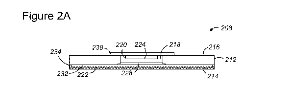
Figures 2A-2I illustrate cross-sectional and perspective views of an impact
target 208
according to an embodiment of the present disclosure. The figures illustrate
various
sections of the impact target 208 at various stages of assembly.
The impact target 208 comprises a plate 212 comprising a front surface 214 and
a rear
surface 216 opposite the front surface 214. The rear surface 214 comprises an
opening
218 which may also be referred to as a cavity, a pocket or an aperture. A
vibration
sensor 220 is fixedly positioned within the opening 218. The vibration sensor
220 is
configured to detect an impact of a sports projectile with the impact target
208.
The impact sensor 208 may comprise an impact surface for receiving an impact
from
a sports projectile. In some examples, the impact surface may comprise the
front
surface 214 of the plate 212. In other examples, the impact target 208 may
comprise
a cover sheet 222 covering the front surface of the 214 of the plate 212. In
such
examples, the impact surface may be provided by the cover sheet 222. The cover
sheet 222 may deform in response to the impact and, in turn, the cover sheet
may
impact the front surface 214 of the plate 212. Either way, the plate 212 is
arranged
with the front surface 214 towards an expected direction of impact.
Positioning the vibration sensor 220 in the opening 218 advantageously locates
the
vibration sensor 220 closer to the impact surface of the impact target 208
thereby
improving sensitivity compared with an impact target with a sensor positioned
on the
rear surface 216. Furthermore, by locating the vibration sensor 220 closer to
vibration
axes in the plane of the plate 212, the vibration sensor 220 can undergo a
larger
vibrational displacement when the plate 212 vibrates in response to an impact,
further
CA 03203924 2023-06-01
WO 2022/118031
PCT/GB2021/053156
6
improving sensitivity. In addition, the enclosed pocket formed by the opening
218 can
concentrate, channel and / or focus air vibrations (or pressure waves) around
the
vibration sensor 220 which can further improve the sensitivity of the impact
target
208, particularly in examples wherein the vibration sensor 220 is a piezo
sensor.
In this example, the vibration sensor comprises a piezo sensor 220. However,
in other
examples the vibration may comprise an accelerometer or other vibration
sensors
known in the art. The piezo sensor 220 includes a sensitive surface 224 that
faces
towards the front surface 214 of the plate 212 and the impact surface. The
sensitive
surface 224 includes an aperture 226 that can detect vibration from acoustic
waves or
pressure waves of air incident on the aperture 226. Such pressure waves may be
provided by movement of the piezo sensor 220 relative to the surrounding air
which
may arise from: (i) movement of the piezo sensor 220 due to its mechanical
coupling
to the plate 212 which can vibrate in response to the impact of the sports
projectile
with the impact surface; and / or (ii) air pressure waves generated within the
opening
218 due to the impact. The piezo sensor 220 can output an electrical signal in
response
to the detection of a pressure wave. The impact target 208 may use the
electrical
signal to provide feedback to the user in any way that is known in the art
including
visual, audio and haptic feedback.
The plate 212 may be considered as a chassis of the impact target 208. The
dimensions
of the plate 212 can affect the sensitivity of the impact target. For example,
thick
plates with larger surface areas may be less sensitive to impacts,
particularly for
impacts located towards the edge of the plate 212. Typically, there may be a
trade-
off between using a thick plate for robustness to high force impacts versus
using a thin
plate to enable a large surface area target. As described herein, the
disclosed impact
targets benefit from an increased sensitivity for a particular set of
dimensions, thereby
alleviating the plate thickness / area / sensitivity trade-off to an extent.
The plate may
comprise wood, metal, metal alloy or high density plastic. In one example, the
plate
comprises High Density Poly Ethylene (HDPE). In some examples, the impact
target
may comprise a 0.5 x 1 m HDPE plate. In other examples, the impact target may
comprise a 1.0 x 1.0 m plywood plate. In further examples, the plate may
comprise a
larger surface area and include multiple openings with respective vibration
sensors as
discussed below in relation to Figure 7.
In this example, the opening 218 extends through a thickness of the plate 212
from
the rear surface 216 to the front surface 214, as can be seen in Figure 2A.
Extending
CA 03203924 2023-06-01
WO 2022/118031
PCT/GB2021/053156
7
the opening through the entire thickness of the plate 212 can make the impact
target
208 easier to manufacture.
In one or more examples, a cross-sectional area of the opening 218 may be
dimensioned to conform to a cross-sectional area of the piezo sensor 220. For
example, a ratio of a cross-sectional area of the opening 218 to a cross
sectional area
of the piezo sensor 220 may be from 1.0 to 5.0, for example, 1.0 to 2.0 or 1.0
to 1.5.
Conforming a cross-section of the opening 218 to the cross-section of the
piezo sensor
220 can provide a snug fit and advantageously improve a coupling between the
piezo
sensor 220 and vibrations in the plate 212. The snug fit may also increase the
robustness of the impact target 208. Minimising a cross-section of the opening
may
also maintain the structural integrity of the plate 212 and provide a robust
impact
target 208.
In this example, the impact target 208 further comprises a cover sheet 222
covering
the front surface 214 of the plate 212. The cover sheet 222 may comprise a
flexible
material which can flex or deform in response to the impact of the sports
projectile.
The cover sheet 222 may be transparent, thereby enabling artwork to be
displayed
between the front surface 214 of the plate 212 and the cover sheet 222. The
cover
sheet 222 can protect the artwork from scuffs resulting from an impact with
the sports
projectile. In
some examples, the cover sheet 222 comprises Polyethylene
Terephthalate Glycol (PETG). PETG is both weatherproof and UV proof, thereby
making
the impact target 208 particularly suitable for outdoor use. The cover sheet
222 can
protect the piezo sensor 220 in the opening 218 from direct impacts with the
sports
projectile.
The cover sheet 222 may be spaced apart from the front surface 214 of the
plate 212
to provide an air gap 232 or spacing between the front surface 214 of the
plate 212
and the cover sheet 222. In response to an impact of a sports projectile with
the cover
sheet 222, the cover sheet 222 will deform towards the front surface 214 of
the plate
212 creating a shockwave or pressure wave in the air gap 232. The shockwave
may
travel through the air gap in a plane parallel to the front surface 214. The
piezo sensor
220 can detect the shockwave as it travels through the air gap 232 to the
opening 218.
The opening 218 may concentrate or focus the shockwave thereby increasing a
magnitude or amplitude of the shockwave as it reaches the aperture 226 of the
piezo
sensor 220. In this way, the cover sheet 222 can further enhance the
sensitivity of
the impact target 208. For example, in a scenario where an impact force of the
sports
projectile hitting the impact target 208 is insufficient to cause vibration of
the plate
CA 03203924 2023-06-01
WO 2022/118031
PCT/GB2021/053156
8
212, the shockwave generated by the cover sheet 222 may still generate a
detectable
pressure wave for the piezo sensor 220.
The impact target 208 may further comprise a compressible seal 234. The
compressible seal 234 may be positioned between the front surface 214 and the
cover
sheet 222 to separate the front surface 214 from the cover sheet 222 and
provide the
air gap 230. The compressible seal 234 may be placed around a perimeter of the
front
surface 214 of the plate 212. The compressible seal 234 may provide the cover
sheet
222 with a spring / elastic effect such that the cover sheet 222 and
compressible seal
it) 234 can
deform in response to an impact before returning to its original shape. The
compressible seal 234 may comprise foam, rubber or any other suitable material
as
known in the art. In one example the compressible seal may comprise ethylene
propylene diene monomer (EPDM).
In some examples, the impact target 208 may comprise a retainer 236 (shown in
Figures 2D and 21) that clamps the plate 212, the cover sheet 222 and the
compressible
seal 234. The retainer 236 may clamp the items with the compressible seal 234
under
partial compression. Figure 2D illustrates a perspective cross-sectional view
at an edge
of the plate 212 of the impact target 208. In this example, the retainer 236
is a
retaining bracket clamping the compressible seal 234 between the cover sheet
222 and
the plate 212 to provide the air gap 232. In some examples, the retaining
bracket
may be provided around the perimeter of the plate 212 to hold the impact
target
together (see Figures 2G to 21).
In the illustrated example, the impact sensor 208 further comprises a cover
plate 228
(visible in Figures 2A, 2C and 2E) overlying or closing the opening 218 on the
front
surface 214 of the plate 212. The cover plate 228 may be fixed to fastenings
230 on
the front surface 214 of the plate 212. The cover plate 228 may reside in a
recess on
the front surface 214.
The cover plate 228 may vibrate or reverberate independently of, or as a
superposition
to, any vibration of the plate 212. As the cover plate 228 is located directly
above the
piezo sensor 220, the vibration of the cover plate 228 can advantageously
increase a
magnitude or amplitude of pressure waves incident on the piezo sensor 220 for
a
particular impact force. The cover plate 228 may vibrate in response to
vibrations of
the plate 212. The cover plate 228 may cooperate with the cover sheet 222 and
vibrate
in response to the shockwave produced by the cover sheet 222. In this way, the
cover
CA 03203924 2023-06-01
WO 2022/118031
PCT/GB2021/053156
9
plate 228 may vibrate in response to impacts with an impact force, or position
of
impact, for which the plate 212 does not vibrate.
In some examples, the cover plate 228 can advantageously provide protection
for the
cover sheet 222. In the absence of a cover plate 228, a sports projectile
incident
directly over the opening 218 may deform the cover sheet into the opening 218
and
cause the cover sheet 222 to fracture. The cover plate 228 can prevent such
excessive
deformation and prevent or reduce the likelihood of any fracturing of the
cover sheet
222.
In some examples, the cover plate 228 may be perforated (comprise one or more
holes). A perforated cover plate may permit air flow into and out of the
opening 218.
As a result, the perforated cover plate may advantageously transfer air
pressure waves
resulting from an impact through the perforated cover plate 228 into the
opening 218.
In some examples, the perforations may transfer the shockwave, provided by the
cover
sheet 222, into the opening 218. This may advantageously concentrate or
increase a
magnitude of the shockwave.
In this example, the piezo sensor 220 is mounted on a mount plate 238 that is
mechanically coupled to the rear surface 216 of the plate 212. The mount plate
238
may be coupled to the rear surface by mechanical fixings and/or fastenings.
The rear
surface 216 of the plate 212 may have one or more nylon fasteners for mounting
the
mount plate mount plate 238 with corresponding fixings. Nylon fasteners may
advantageously allow the mount plate 238 to vibrate and the nylon fasteners to
flex
without working loose from the rear surface 216.
The piezo sensor 220 may be mechanically mounted on the mount plate 238.
Mechanically coupling the piezo sensor 220 to the plate 212 can provide a
robust
impact target 208 that can withstand high impact forces without dislocation of
the
piezo sensor 220. The mechanical mount plate 238 may comprise a clamp 240 for
securing wires of the piezo sensor 220 and wires of a connection port 242 to
further
improve robustness to high impact forces. Securing wiring of the impact target
208
can prevent wiring joint dislocation resulting from repetitive high impact
forces.
In some examples, the impact target 208 may comprise a second compressible
seal
(not illustrated) between the rear surface 216 and the mount plate 238. The
second
compressible seal can enable the mount plate 238 to vibrate or flex relative
to the
plate 212 in response to an impact with the target surface. For example, the
mount
CA 03203924 2023-06-01
WO 2022/118031
PCT/GB2021/053156
plate 238 may tend to vibrate at a different natural vibration frequency to
the plate
212. The second compressible seal may also provide water ingress protection to
the
opening 208 aiding suitability of the impact target 208 for outdoor use.
5 In some examples, the mount plate 238 may be directly mechanically
coupled or
connected to the cover plate 228. For example, one or more struts 244 (shown
in
Figure 2E) or transfer studs may extend between and connect the mount plate
238
and the cover plate 228. In this way, vibrations on the cover plate 228 may be
transferred to the mount plate 238 and the piezo sensor 220, further enhancing
10 sensitivity of the impact target 208.
Figures 2G and 2H illustrate views of the front of the impact target 208 fully
assembled.
Artwork is installed under the cover sheet 222 obscuring the view of the cover
plate
218. The retaining brackets 236 extend around the perimeter of the impact
target
208.
Figure 21 illustrates a perspective view of the rear of the impact target 208
fully
assembled. The mount plate 238 is installed over the opening 218. The
connection
port 242 is accessible for connection to external circuitry. As discussed
below, the
connection port 242 can provide an output signal from the piezo sensor 220 in
response
to impacts of the sports projectile with the impact target 208. The connection
port
may also provide electrical power to circuitry of the impact target 208
Figure 3 illustrates the operation of the impact target 308 of Figure 2 in
response to
an impact with a sports projectile, according to an embodiment of the present
disclosure.
In this example, a sports projectile in the form of a ball 304 impacts the
impact target
308. In Figure 3, the impact surface comprises the cover sheet 322. The cover
sheet
322 deforms in response to the impact force exerted by the ball 304. The cover
sheet
322 deforms such that the cover sheet 322 impacts the front surface 314 of the
plate
312. In this way, the cover sheet 322 can transfer the impact force of the
ball 304 to
the front surface 314. The impact of the ball 304 on the cover sheet 322
produces a
shockwave 348 in the air gap 332 between the cover sheet 322 and the plate
312.
The shockwave 348 travels along a plane parallel to the front surface 314
towards the
opening 318. The cover plate 328 may vibrate in response to the shockwave 348
to
transfer energy in the shockwave (via an air pressure wave) to the opening 318
and
the piezo sensor 320. Any perforations in the cover plate 328 may also
transfer and
CA 03203924 2023-06-01
WO 2022/118031
PCT/GB2021/053156
11
may concentrate energy in the shockwave (via a pressure wave) into the opening
318
and onto the piezo sensor 320.
The impact of the cover sheet 322 on the front surface 314 of the plate, in
response
to the impact of the ball 304, also produces a vibration 346 in the plate 312.
The plate
312 may vibrate about an axis 350 through a centre of the thickness of the
plate
parallel to the front surface 314. The piezo sensor 320 can detect the
vibration 346 of
the plate 312 as it is mechanically coupled to the plate 312 via mount plate
338. The
piezo sensor 320 may undergo a large displacement in response to the vibration
because of the position of the piezo sensor 320 close to the axis 350. The
motion of
the piezo sensor 320 within the opening 318 relative to the surrounding air
may further
amplify the sensing effect.
In summary, the piezo sensor 320 is arranged within an opening / cavity of the
plate
312 to enhance its sensitivity to vibrations 346 of the plate 312 and
shockwaves 348
produced by the cover sheet 322. Placing the piezo sensor 320 within the
opening and
closer to the front surface 314 than if it was mounted on the rear surface 316
can
improve sensitivity to impacts of the plate 312. In turn, this can enable a
relatively
large impact target to be produced that can adequately sense an impact at its
periphery.
Figure 4 illustrates an impact target 408 according to a further aspect of the
present
disclosure. Features of the impact target that are present in the embodiment
of Figure
2 have been given corresponding numbers in the 400 series and will not
necessarily
be described again here.
The impact target 408 comprises a plate 412 comprising a front surface 414 and
a rear
surface 416 opposite the front surface 414. The rear surface 414 comprises an
opening
418. A vibration sensor 420 is fixedly positioned within the opening 418. The
vibration
.. sensor 420 is configured to detect an impact of a sports projectile with
the impact
target 408.
In this embodiment, the opening 418 extends through the entire thickness of
the plate
412. However, the impact target 408 comprises neither the cover plate nor
cover
.. sheet of Figure 2. The impact target 408 provides a simple arrangement with
minimal
components. In some examples, a cross-section of the opening may have a
diameter
that is smaller than a diameter of the sports projectile. This can
advantageously
CA 03203924 2023-06-01
WO 2022/118031
PCT/GB2021/053156
12
prevent the sports projectile from directly impacting the vibration sensor 420
and
prevent it being damaged by the projectile.
Positioning the vibration sensor 420 in the opening 418 advantageously locates
the
vibration sensor 420 closer to the impact surface (the front surface 416 in
this
example) of the impact target 408 thereby improving sensitivity compared with
an
impact target with a sensor positioned on the rear surface 416. Furthermore,
by
locating the vibration sensor 420 closer to vibration axes in the plane of the
plate 412,
the vibration sensor can undergo a larger vibrational displacement when the
plate 412
vibrates in response to an impact, further improving sensitivity. In addition,
the
channel formed by the opening 418 can concentrate, channel and / or focus air
vibrations (or pressure waves) around the vibration sensor 420 which can
further
improve the sensitivity of the impact target 408, particularly if the
vibration sensor
comprises a piezo sensor.
The vibration sensor 420 can advantageously detect vibrations in the plate 412
in the
same way as described above in relation to Figure 2. In some examples, the
vibration
sensor may comprise a piezo sensor 420 which may detect air vibrations or
pressure
waves that travel along the front (impact) surface 416 in response to an
impact with a
sports projectile. The pressure waves can channel and concentrate into the
opening
418 arriving at the piezo sensor 420.
Figure 5 illustrates a further impact target 508 according to another
embodiment of
the present disclosure. Features of the impact target 508 that are present in
the
embodiment of Figure 2 have been given corresponding numbers in the 500 series
and
will not necessarily be described again here.
The impact target 508 comprises a plate 512 comprising a front surface 514 and
a rear
surface 516 opposite the front surface 514. The rear surface 514 comprises an
opening
518. A vibration sensor 520 is fixedly positioned within the opening 518. The
vibration
sensor 520 is configured to detect an impact of a sports projectile with the
impact
target 508.
In this example, the opening 518 extends partially through the thickness of
the plate
512. As a result, an integral cover 552 (integral to the plate 512) separates
the
opening 518 from the front surface 514 and the impact surface.
CA 03203924 2023-06-01
WO 2022/118031
PCT/GB2021/053156
13
In the same way as the examples discussed above, the vibration sensor 520 is
located
in opening 518 of the impact target 508 such that it has improved sensitivity.
In this
example, the vibration sensor is a piezo sensor 520.
In this example, the impact surface comprises the cover sheet 522. The cover
sheet
522 may produce a shockwave in the same way as described in relation to Figure
2.
The integral cover 552 may have a natural vibration frequency different to a
natural
vibration frequency of the plate 512. As a result, the integral cover may
vibrate or
reverberate at its own frequency directly in front of the opening 518 and the
piezo
sensor 520. In this way, the integral cover 552 may function in a similar way
to the
cover plate of Figure 2 and increase a magnitude or amplitude of air
vibrations in the
opening 518 and incident on the piezo sensor 520. The integral cover 552 may
vibrate
in response to vibrations of the plate 512 and / or in response to the
shockwave
produced by the cover sheet 522.
In some examples, the integral cover may comprise one or more perforations for
transferring pressure waves from the air gap 532 to the opening 518 in the
same way
as described in relation to the cover plate of Figure 2.
In one or more further example impact targets, the vibration sensor may be an
accelerometer or other vibration sensor known in the art. Although the example
impact
targets of Figures 2 to 5 are predominantly disclosed in relation to a piezo
sensor the
features of each of the figures may equally apply to an impact target
comprising a
vibration sensor other than a piezo sensor. Only features that solely rely on
the direct
detection of an air pressure wave incident on the aperture of the piezo sensor
may not
apply to other vibration sensors such as an accelerometer. However, impact
targets
incorporating other vibration sensors such as an accelerometer may indirectly
detect
an air pressure wave. For example, if the piezo sensor of Figure 2 was
replaced with
an accelerometer, the accelerometer could indirectly detect the air shock wave
produced by the cover sheet in examples including a cover plate mechanically
connected to the mount plate. A person skilled in the art will appreciate that
all
features of Figures 2 to 5 not related to the direct detection of an air
pressure wave
can apply to impact targets comprising an accelerometer or other vibration
sensor. For
example, features related to: detection of the mechanical vibration of the
plate; the
mechanical arrangement of the impact target; the opening; the mount plate; the
cover
sheet; the cover plate; the first and second compressible seals; the transfer
struts;
CA 03203924 2023-06-01
WO 2022/118031
PCT/GB2021/053156
14
the retainer, among others may be implemented in embodiments comprising an
accelerometer or other non-piezo based vibration sensor.
The vibration sensor of all embodiments is arranged to detect an impact of a
sports
projectile with the impact target. The vibration sensor may detect vibrations
of the
plate and / or air vibrations or pressure waves resulting from the impact.
The vibration sensor may generate an electrical signal in response to
detecting the
impact. For example, the air pressure waves or acoustic waves incident on a
piezo
element of the piezo sensor may alter a resistance of the piezo element which
can be
detected by circuity. As a further example, an accelerometer can provide an
electrical
signal in response to mechanical vibrations. Such operations are known in the
art and
not described in detail here.
The impact target may comprise circuity for generating an output signal in
response to
the electrical signal. The output signal may comprise the electrical signal or
may
comprise parameters of the electrical signal, an amplified version of the
electrical signal
and / or a digital representation of the electrical signal. The impact target
may
comprise one or more transmission components for transmitting the output
signal. For
example, the impact target may provide for wireless or wired communication
(for
example via the connection port) for transmitting the output signal to a
remote
processor. The remote processor may form part of a sports simulator and
provide
feedback to a user. The feedback may comprise an indication that the impact
target
has been hit or a score dependent on the impact force, impact target location
and / or
a time of impact. The feedback may be provided by LEDs or a display screen.
In some examples, the impact target may comprise a visual indicator for
providing the
feedback directly to the user. The visual indicator may be directly connected
to the
vibration sensor or circuitry and provide near instantaneous feedback to the
user. For
example, the impact target may comprise one or more LEDs, LCDs or other
display
devices suitable for providing the feedback to the user.
In some examples, the impact target may comprise a processor for processing
the
electrical signal from the vibration sensor. The processor may control the
visual
indicator in response to the electrical signal. Alternatively, the processor
may control
a communication module to communicate the output signal to an external screen,
device or processor.
CA 03203924 2023-06-01
WO 2022/118031
PCT/GB2021/053156
In some examples, the processor may apply one or more thresholds to the
electrical
signal from the vibration sensor. For example, the processor may apply a lower
level
threshold to the electrical signal. The processor may determine an electrical
signal to
correspond to an impact at the impact target if a level of the electrical
signal is greater
5 than or
equal to the lower level threshold. The processor may determine an electrical
signal to correspond to ambient noise or ambient vibrations if a level of the
electrical
signal is less than the lower level threshold. In this way, the impact target
may avoid
false positive impact detections arising from ambient noise or vibrations (for
example
a user walking past the impact target).
In some examples, the impact target may comprise one or more mechanical
dampers.
The one or more mechanical dampers can isolate the impact target from
vibrations in
its surrounding environment. The mechanical dampers may form part of a stand
or
mounting bracket for positioning the impact target. Isolating the impact
target from
vibrations in the surrounding environment can further improve the sensitivity
of the
impact target to low force impacts.
Figure 6 illustrates a further impact target 608 according to an embodiment of
the
present disclosure.
The impact target 608 comprises two assemblies according to the example of
Figure 2
mechanically coupled back to back. The impact target 608 operates under the
same
principles as the example of Figure 2. However, the back to back arrangement
provides
at least two opposing impact surfaces that are sensitive to impacts with a
sports
projectile. The impact target 608 may be particularly suitable for use as a
backstop
target in a baseball simulator or a wicket in a cricket simulator. The impact
target may
be sensitive to impacts from any direction making it particularly suitable for
simulation
of a run-out.
Figure 7 illustrates a further impact target 708 according to an embodiment of
the
present disclosure.
In this example, the impact target 708 comprises a plurality of vibration
sensors
housed in a respective plurality of openings 718-A, 718-B, 718-C, 718-D on the
rear
surface of the plate. In this example, the impact target comprises four
vibration
sensors arranged in four quadrants of the impact target. Providing a plurality
of
vibration sensors can be particularly advantageous for large area impact
targets such
as those used as the display screen in Figure 1. Providing a plurality of
vibration
CA 03203924 2023-06-01
WO 2022/118031
PCT/GB2021/053156
16
sensors may also enable the impact target to determine a position of impact on
the
impact surface. In this example, each vibration sensor can produce a
corresponding
electrical signal. The impact target may provide an output signal as described
above
in relation to the other sensors. The impact target may comprise a processor
for
receiving the plurality of electrical signals. The processor may determine a
position of
impact on the impact surface based on the relative magnitudes of the plurality
of
electrical signals.
The disclosed impact targets comprise an opening in the rear surface of the
plate that
advantageously increases a sensitivity of the vibration sensor to impacts of
the impact
target with a sports projectile. As a result, the plate can be made thicker to
improve
the robustness of the impact target to high force impacts. Typically, a
thicker plate
responds less to a particular impact resulting in reduced sensitivity,
particularly at the
edges of the impact plate. A relatively thick plate can also be useful in
enabling the
impact target to house one or feedback components (such as a strip of LEDs)
within
its thickness. The increased impact sensitivity of the disclosed impact
targets allows
the use of thick plates that can withstand high impact forces such as a
baseball or
cricket ball travelling at a velocity of the order of 100 mph, while
maintaining sensitivity
for low force impacts.
Therefore, the disclosed impact targets provide a robust impact target that
can
withstand high impact force while maintaining a high sensitivity to register
weak impact
forces and avoid missing low force impacts and the resulting user frustration.
In this
way, the impact sensor can detect a wide range of impact force.
An impact target according to the embodiment of Figure 2 has undergone testing
with
a cricket ball launched at between 25 mph and 90 mph. The impact target
withstood
> 10,000 impacts at 90 mph without failure. The impact target also maintained
a hit
detection rate of > 99% for > 20,000 impacts at 25 mph.