Sélection de la langue

Search

Sommaire du brevet 3205078 

Énoncé de désistement de responsabilité concernant l'information provenant de tiers

Une partie des informations de ce site Web a été fournie par des sources externes. Le gouvernement du Canada n'assume aucune responsabilité concernant la précision, l'actualité ou la fiabilité des informations fournies par les sources externes. Les utilisateurs qui désirent employer cette information devraient consulter directement la source des informations. Le contenu fourni par les sources externes n'est pas assujetti aux exigences sur les langues officielles, la protection des renseignements personnels et l'accessibilité.

Disponibilité de l'Abrégé et des Revendications

L'apparition de différences dans le texte et l'image des Revendications et de l'Abrégé dépend du moment auquel le document est publié. Les textes des Revendications et de l'Abrégé sont affichés :

  • lorsque la demande peut être examinée par le public;
  • lorsque le brevet est émis (délivrance).
(12) Demande de brevet: (11) CA 3205078
(54) Titre français: ENSEMBLE DE FIXATION DE CARTE DE CIRCUIT IMPRIME
(54) Titre anglais: CIRCUIT BOARD FASTENER ASSEMBLY
Statut: Demande conforme
Données bibliographiques
(51) Classification internationale des brevets (CIB):
  • H05K 3/36 (2006.01)
(72) Inventeurs :
  • COLOSI, ANTHONY (Etats-Unis d'Amérique)
(73) Titulaires :
  • PENN ENGINEERING & MANUFACTURING CORP.
(71) Demandeurs :
  • PENN ENGINEERING & MANUFACTURING CORP. (Etats-Unis d'Amérique)
(74) Agent: SMART & BIGGAR LP
(74) Co-agent:
(45) Délivré:
(86) Date de dépôt PCT: 2021-12-10
(87) Mise à la disponibilité du public: 2022-06-16
Licence disponible: S.O.
Cédé au domaine public: S.O.
(25) Langue des documents déposés: Anglais

Traité de coopération en matière de brevets (PCT): Oui
(86) Numéro de la demande PCT: PCT/US2021/062840
(87) Numéro de publication internationale PCT: WO 2022125921
(85) Entrée nationale: 2023-06-09

(30) Données de priorité de la demande:
Numéro de la demande Pays / territoire Date
63/124,433 (Etats-Unis d'Amérique) 2020-12-11

Abrégés

Abrégé français

La présente invention concerne un système de fixation qui comprend deux composants d'interconnexion pour fixer des composants électroniques qui peuvent être joints par encliquetage lorsqu'un élément de fixation est pressé contre un élément de retenue. Le système de fixation est constitué d'un goujon de fixation ayant une base plane au fond et une tige s'étendant vers le haut avec une partie de col de diamètre réduit adjacente à la base. Le goujon comprend une partie sphérique ayant une surface supérieure plane plate au niveau d'une extrémité supérieure distale. Le goujon de fixation s'accouple avec un élément de retenue ayant une base plane et des bras élastiques opposés fixés s'étendant orthogonalement à partir de la base centrée autour d'un axe de rotation. Les bras présentent de préférence des surfaces internes en forme de composé symétriques autour de l'axe. Ces surfaces comprennent une partie cylindrique adjacente à la base et une partie sphérique adjacente aux extrémités distales des bras.


Abrégé anglais

A fastening system comprises two interconnecting components for fastening electronic components which can be joined by snap-fit when a fastener component is pressed against a retainer. The fastening system consists of a fastener stud with a planar base at the bottom and an upwardly extending shank with a neck portion of reduced diameter adjacent the base. The stud has a spherical ball portion with a flat planar top surface at a distal top end. The fastener stud mates with a retainer having a planar base and affixed opposing resilient arms extending orthogonally from the base centered about a rotational axis. The arms preferably have compound shaped inner surfaces symmetrical about the axis. These surfaces comprise a cylindrical portion adjacent the base and a spherical portion adjacent the distal ends of the arms.

Revendications

Note : Les revendications sont présentées dans la langue officielle dans laquelle elles ont été soumises.


5
Claims
What is claimed is:
1. A fastening assembly consisting of two interconnected elements for joining
electronic
components, compromising:
a fastener stud with a planar base at the bottom and an upwardly extending
shank with
a neck portion of reduced diameter adjacent the base, the shank having a
spherical ball
portion with a flat planar top at a distal top end of the fastener stud;
a retainer with a planar base and having affixed opposing resilient arms
extending
orthogonally from the base centered about a rotational axis, said arms having
compound
shaped inner surfaces symmetrical about the axis consisting of a cylindrical
portion adjacent
the base and a spherical portion adjacent the distal ends of the arms; and
wherein the retainer arms and fastener stud are joined by non-destructive
releaseable
snap-fit.
2. The assembly of claim 1 wherein the top of the fastener stud abuts the
retainer base.
3. The assembly of claim 1 wherein there are only two arms.
4. The assembly of claim 1 wherein an outer surface of the retainer base is
planar and
orthogonal to the axis.
5. The assembly of claim 4 wherein an outer surface of the fastener stud base
is planar and
orthogonal to the axis.
6. The assembly of claim 5 wherein the outer surfaces of the retainer and
fastener stud bases
are adapted for surface mount soldering and pick-and-place transportation.
7. The assembly of claim 6 wherein the fastener stud and/or the retainer is
soldered to an
electronic component.
8. The assembly of claim 7 wherein the electronic component is a circuit
board.
9. The assembly of claim 2 wherein an inner surface of the retainer base is
planar and in
abutment with the fastener stud top end.

6
10. The assembly of claim 1 wherein the ends of the arms are located adjacent
the fastener
stud neck portion and in between the spherical portion of the fastener stud
and its base.
11. The assembly of claim 10 wherein the inner surface of the ends of the arms
matches the
contour of the fastener stud ball portion.
12. The assembly of claim 1 wherein the distal ends of the retainer arms are
axially rounded.
13. The assembly of claim 11 wherein the fastener stud and the retainer are
constructed and
adapted such that they are joined when the fastener stud is pressed against
the retainer arms
askew to the rotational axis.

Description

Note : Les descriptions sont présentées dans la langue officielle dans laquelle elles ont été soumises.

CA 03205078 2023-06-09
WO 2022/125921
PCT/US2021/062840
CIRCUIT BOARD FASTENER ASSEMBLY
Related Applications
This is a PCT patent application related to provisional patent application
serial
number 63/124,433, entitled, "Circuit Board Fasteners and Their Assembly"
filed on
December 11, 2020 priority from which is hereby claimed.
Field of Invention
The present invention relates to two-part fastener systems which have
separable
components that releaseably join together. More specifically it relates to
surface mounted
metal fasteners of this type used to join circuit boards in spaced relation to
each other.
Background of the Invention
In the field of circuit board fasteners, it is known to use fasteners soldered
or otherwise
affixed to a circuit board to join two circuit boards spaced apart. For
various reasons these
fasteners have various drawbacks in meeting the requirements of modern high-
speed robotic
assembly. Those requirements include compatibility with pick-and-place
robotics, delivery to
the installation site by tape-and-reel feed, and circuit board surface mount
soldering
technology.
Summary of the Invention
It is therefore the main objective of the present invention to overcome the
present
drawbacks in the field of circuit board fastening as explained above. As
further described
below in the drawings and description of one preferred embodiment of the
invention, the
present system consists of a fastener pair of two separate mating components.
One of the
components is a fastener stud with a ball end and the other is a retainer
which receives the
ball end by snap fit. These components utilize surface mount technology in an
effective way
that accomplishes the following attributes:
1. The two components of the fastener assembly pair are mounted separately but
can be
assembled on a center axis.
2. The fastener pair allows for assembly and disassembly by hand for several
cycles
without the need for tools.
3. The fastener pair can be assembled at an angle (orthogonal or non-
orthogonal
approach angle).

CA 03205078 2023-06-09
WO 2022/125921
PCT/US2021/062840
2
4. The fastener pair can be made available on tape-and-reel feed and mounted
via SMT
(solderable surface mount technology).
5. The components can act as a spacer that holds a tight-tolerance assembled
height.
6. The fastener pair can be oriented at an angle about the axis of assembly
upon
placement.
More specifically, the applicant has invented two interconnecting components
for
fastening electronic components which can be joined by snap-fit when the
fastener
component is pressed against a retainer. The fastening system comprises a
fastener stud with
a planar base at the bottom and an upwardly extending shank with a neck
portion of reduced
diameter adjacent the base. The stud has a spherical ball portion with a flat
planar top surface
at a distal top end. The fastener stud mates with a retainer having a planar
base and affixed
opposing resilient arms extending orthogonally from the base centered about a
rotational axis.
The arms preferably have compound shaped inner surfaces symmetrical about the
axis.
These surfaces comprise a cylindrical portion adjacent the base and a
spherical portion
adjacent the distal ends of the arms. The retainer and fastener are
constructed and arranged
such that the fastener is received between the retainer arms by releasable
snap fit. The
spherical portion of the retainer arms inside surface preferably matches the
contour of the
fastener ball portion adjacent the fastener neck.
In some embodiments the top of the fastener stud abuts the retainer base and
there are
only two retainer arms. The retainer base can have an outer surface of the
retainer base is
planar and orthogonal to the axis and an outer surface of the fastener base is
planar and
orthogonal to the axis as well. The outer surfaces of the retainer and
fastener bases are
preferably adapted for surface mount soldering and pick-and-place
transportation during
electronic component manufacturing where the fastener and/or the retainer is
soldered to an
electronic component such as a circuit board.
Greater stability of the joined fastener and retainer can be provided by a
construction of
the parts where an inner surface of the retainer base is planar and in
abutment with the
fastener top while the ends of the retainer arms are located adjacent the neck
portion and in
between the spherical portion and the base of the fastener.
Other objects and advantages will be apparent to those in the field of
electronic fastener
arts from the following drawings and description of the disclosed embodiments.
Description of the Drawings
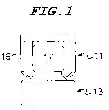
Figure 1 is a front elevation view of the assembled fastener and retainer.
Figure 2 is a sectional view taken from Fig. 1 as shown in that figure.

CA 03205078 2023-06-09
WO 2022/125921
PCT/US2021/062840
3
Figure 3 is a front elevation view of the retainer element.
Figure 4 is a front elevation of the fastener stud element.
Figures 5, 6, and 7 are top front perspective views showing various rotational
positions
of the retainer element shown in isolation.
Figure 8 is a side elevation view showing the orientation of the fastener and
retainer
elements in an orthogonal assembly position.
Figure 9 is a side elevation view showing a non-orthogonal assembly position
of the
elements prior to assembly.
Description of the Preferred Embodiment
Referring to Figures 1 and 2, the two main elements of the invention, a
retainer 11 and
a fastener stud 13, are shown in their assembled condition. The retainer has
flexible resilient
arms 15 that capture a spherical ball end 17 of a fastener shank by non-
destructive releaseable
snap fit. The arms 15 bend when they interfere with the fastener ball surface
to receive the
fastener shank when pressed together upon assembly. The arms have sufficient
elasticity to
return to an assembled resting position as shown in the cross-section seen in
figure 2. The
ends of the arms are located adjacent a fastener stud neck portion and in
between the
spherical portion of the fastener stud and its base.
Referring now to Figure 3, the retainer 11 is shown in isolation. The retainer
11
comprises a planar base 25 and affixed opposing resilient arms 15 extending
orthogonally
from the base 25 centered about a rotational axis 14. The arms have compound
shaped inner
surfaces symmetrical about the axis consisting of a cylindrical portion 27
adjacent the base 25
and a spherical portion 29 adjacent rounded distal ends 31 of the arms. The
base 25 has a flat
bottom surface 26. The cylindrical portion provides the lateral capture of the
stud over a
range of axial spacing.
As seen in Figure 4, the fastener stud has a shank that extends upwardly from
a base
19, and further consists of a neck portion 21 and a partially spherical ball
end 17. The
fastener stud has a flat top 33 and a flat bottom surface 20. When assembled,
as seen in
Figure 1, the parts will be aligned with a planar flat top 33 of the spherical
portion 17 of the
fastener in flush abutment with the planar inner surface 35 of the base 25 of
the retainer. This
construction provides a fixed spacer height for the mated affixed structures
such as circuit
boards to which the bases 25 and 19 of the individual elements are separately
attached at
outer surfaces 26 and 20 respectively. The abutment of the mating flat
surfaces also provides
greater stability of components affixed to outer surfaces of the
interconnecting

CA 03205078 2023-06-09
WO 2022/125921
PCT/US2021/062840
4
fastener/retainer assembly by resisting off-axis tipping of the assembly. The
retainer 11 can
be revolved about a rotational assembly axis defined by axis 14 as seen in
figure 3.
The flat surfaces seen in Figures 3 and 4 reveal the SMT (surface mount
technology)
compatibility aspects of the invention. Seen in these figures are surfaces 35,
26, 33 and 20
which are the primary pick-and-place surfaces translating each part by an
applied vacuum. In
cases where the vacuum nozzle may not fit between the arms of the retainer, a
patch may be
applied at the top of the arms for transfer using that surface. For SMT
compatibility, the
parts can be soldered on the outer surfaces 26 and 20 of bases 25 and 19
respectively.
Figures 5, 6, and 7 show different orientations of the retainer. The invention
allows for
assembly at any orientation of the retainer about the assembly axis so long as
the ball-end
fastener is aligned axially as well. This eliminates the need for precise
alignment when
placing the part on the PCB.
Referring now to figures 7 and 8, figure 7 shows an example of an orthogonal
assembly which occurs when assembling by pressing the parts 11 and 13 together
along the
assembly axis as shown by the direction arrow. Figure 8 shows a non-orthogonal
assembly
which occurs when the components are assembled by being pressed together at an
angle
askew to the vertical rotational axis of the retainer. The axially rounded
contact points of the
retainer and rounded surface of the fastener ball allow for this non-
orthogonal assembly.
From the foregoing it will be apparent to those of skill in the art that the
functional
advantages and objectives of the invention have been achieved. It should be
understood that
the embodiment shown represents but one possible manifestation of the
invention. There are
other variations and alterations that are possible which utilize the basic
principles of
operation of the fastening system described herein without departing from the
scope and
spirit of the invention which is determined by the following claims and their
legal
equivalents.

Dessin représentatif
Une figure unique qui représente un dessin illustrant l'invention.
États administratifs

2024-08-01 : Dans le cadre de la transition vers les Brevets de nouvelle génération (BNG), la base de données sur les brevets canadiens (BDBC) contient désormais un Historique d'événement plus détaillé, qui reproduit le Journal des événements de notre nouvelle solution interne.

Veuillez noter que les événements débutant par « Inactive : » se réfèrent à des événements qui ne sont plus utilisés dans notre nouvelle solution interne.

Pour une meilleure compréhension de l'état de la demande ou brevet qui figure sur cette page, la rubrique Mise en garde , et les descriptions de Brevet , Historique d'événement , Taxes périodiques et Historique des paiements devraient être consultées.

Historique d'événement

Description Date
Lettre envoyée 2023-07-17
Demande reçue - PCT 2023-07-13
Inactive : CIB en 1re position 2023-07-13
Inactive : CIB attribuée 2023-07-13
Exigences applicables à la revendication de priorité - jugée conforme 2023-07-13
Exigences quant à la conformité - jugées remplies 2023-07-13
Demande de priorité reçue 2023-07-13
Exigences pour l'entrée dans la phase nationale - jugée conforme 2023-06-09
Demande publiée (accessible au public) 2022-06-16

Historique d'abandonnement

Il n'y a pas d'historique d'abandonnement

Taxes périodiques

Le dernier paiement a été reçu le 2023-11-06

Avis : Si le paiement en totalité n'a pas été reçu au plus tard à la date indiquée, une taxe supplémentaire peut être imposée, soit une des taxes suivantes :

  • taxe de rétablissement ;
  • taxe pour paiement en souffrance ; ou
  • taxe additionnelle pour le renversement d'une péremption réputée.

Veuillez vous référer à la page web des taxes sur les brevets de l'OPIC pour voir tous les montants actuels des taxes.

Historique des taxes

Type de taxes Anniversaire Échéance Date payée
Taxe nationale de base - générale 2023-06-09 2023-06-09
TM (demande, 2e anniv.) - générale 02 2023-12-11 2023-11-06
Titulaires au dossier

Les titulaires actuels et antérieures au dossier sont affichés en ordre alphabétique.

Titulaires actuels au dossier
PENN ENGINEERING & MANUFACTURING CORP.
Titulaires antérieures au dossier
ANTHONY COLOSI
Les propriétaires antérieurs qui ne figurent pas dans la liste des « Propriétaires au dossier » apparaîtront dans d'autres documents au dossier.
Documents

Pour visionner les fichiers sélectionnés, entrer le code reCAPTCHA :


Pour visualiser une image, cliquer sur un lien dans la colonne description du document. Pour télécharger l'image (les images), cliquer l'une ou plusieurs cases à cocher dans la première colonne et ensuite cliquer sur le bouton "Télécharger sélection en format PDF (archive Zip)" ou le bouton "Télécharger sélection (en un fichier PDF fusionné)".

Liste des documents de brevet publiés et non publiés sur la BDBC .

Si vous avez des difficultés à accéder au contenu, veuillez communiquer avec le Centre de services à la clientèle au 1-866-997-1936, ou envoyer un courriel au Centre de service à la clientèle de l'OPIC.


Description du
Document 
Date
(aaaa-mm-jj) 
Nombre de pages   Taille de l'image (Ko) 
Abrégé 2023-06-09 1 60
Revendications 2023-06-09 2 51
Description 2023-06-09 4 198
Dessins 2023-06-09 2 65
Dessin représentatif 2023-06-09 1 7
Page couverture 2023-09-28 1 43
Courtoisie - Lettre confirmant l'entrée en phase nationale en vertu du PCT 2023-07-17 1 594
Rapport de recherche internationale 2023-06-09 1 52
Demande d'entrée en phase nationale 2023-06-09 6 173