Note : Les descriptions sont présentées dans la langue officielle dans laquelle elles ont été soumises.
1
Filter element for an air filter device of a motor vehicle and air filter
device
The invention relates to a filter element for an air filter device of a motor
vehicle, having a
frame which at least partially surrounds a filter material of the filter
element. The frame
comprises a front wall which extends essentially perpendicularly to an
insertion direction.
The filter element can be inserted into a receiving space of a housing of the
air filter
device in the insertion direction. At least one fastening element is arranged
on a front side
of the front wall. A cover of the air filter device designed to close the
receiving space can
be fixed to the fastening element. The invention further relates to an air
filter device having
such a filter element.
DE 198 04 452 Al shows an air filter for an air conditioning system of a motor
vehicle with
a filter housing with an insertion opening for a filter insert, wherein the
opening can be
closed by means of a cover which is firmly connected to the filter insert. On
its outer side,
with which it comes into contact with the housing, the cover projects beyond
the insertion
opening. The side of the cover pointing inwards - in the insertion direction -
corresponds
in its extension to the width of the insertion opening and has a rigid locking
lug on one
side, which engages behind a corresponding edge of the filter housing in the
closed state.
The correct seating of the cover in the closed insertion opening is ensured by
an
elastically deformable seal running around approximately centrally between the
outer and
inner sides of the cover.
DE 20 2005 005 067 Ul shows a filter element for use in a filter receptacle,
wherein the
access opening provided for inserting the filter element in the filter
receptacle can be
closed via a separate closure element. For this purpose, hook-shaped fastening
elements
that are aligned with one another project from the closure element and are
assigned
corresponding recesses on the filter receptacle. To form a seal between the
closure
element and the filter receptacle, the filter element has a flat sealing
element on its end
face facing the closure element, which projects beyond the edge of the end
face on all
sides, wherein engaging openings for inserting the fastening elements are
formed in the
protrusions.
DE 10 2015 003 297 Al describes an air filter device for a motor vehicle
comprising a
housing, in which a filter element can be received, and a cover. The filter
element has at
least one latching device in the form of two opposing retaining tabs or
eyelets that can be
moved in opposite directions, which, as soon as the filter element is inserted
into the
CA 03205333 2023-7- 14
2
housing and the cover is placed thereon, can be latched to corresponding
retaining lugs
on the housing and on the cover, whereby the three interacting parts are
sealed from one
another.
DE 10 2017 007 497 Al shows an air filter for a motor vehicle, in which, in
turn, a filter
element is inserted through an insertion opening into the housing of the air
filter and the
insertion opening can be closed in a sealing manner by a cover element. The
filter
element has at least one retention element with a fastening element, wherein
the retention
element latches behind when the filter element is inserted in the housing,
wherein the
fastening element connected to the retention element is then in a position in
which a
locking strut assigned to the cover element can be passed through a passage
opening in
the fastening element and rotated, whereby the cover is connected in a sealed
manner to
the housing.
DE 10 2007 018 215 Al describes an air filter for an air conditioning system
of a motor
vehicle, in which a frame runs around a folded filter medium. Two receptacles
project from
one wall of the frame, into which latching means can be inserted. The latching
means are
arranged on a cover with which a housing can be closed, in which the frame
with the
folded filter medium is received. In this regard, a sealing element, which
bears against the
edge of the housing when the housing is closed by means of the cover, is
formed in one
piece with a connecting plate of the cover.
With such an air filter, it has proven difficult to handle the cover in such a
way that the
latching means can latch in the receptacles. One of the reasons for this is
that a defined
installation position of the frame in the housing is not specified.
In addition, the two latching means arranged on the cover must be precisely
aligned so
that they can be inserted into the receptacles. This is particularly difficult
when the
receptacles are not easily visible to a person involved in the assembly of the
cover.
Furthermore, DE 10 2015 004 645 Al describes a filter element for filtering
combustion air
which is supplied to an internal combustion engine of a motor vehicle. The
filter element
has a filter medium body, which is supported and held on an internal carrier
body in the
form of a support structure. End plates are located on axial end faces of the
carrier body.
Two tab-shaped components, which have respective latching elements, are
connected to
one of the end plates via respective connecting parts. The components with the
respective
latching elements are formed in one piece with the end plate via the
connecting parts.
CA 03205333 2023-7- 14
3
Furthermore, the components project from the filter element in the lateral
direction. In an
installation position of the filter element, the latching elements latch with
counter-latching
elements which are arranged on a filter housing. The latching elements are
secured in a
latching position by means of a cover placed on the filter housing.
A disadvantage here is the fact that the laterally protruding components with
the latching
elements take up a comparatively large amount of installation space inside the
filter
housing, which can therefore not be used or is not available for filtering the
air to be
filtered.
In addition, with this air filter device, the cover can also be attached to
the filter housing
when there is no filter element in the filter housing. This is also
disadvantageous.
The object of the present invention is to create a filter element of the type
mentioned at
the outset, which simplifies the closing of the receiving space by means of
the cover, and
to specify an air filter device having such a filter element.
This object is achieved by a filter element having the features of claim 1 and
an air filter
device having the features of claim 6. Advantageous configurations with
expedient further
developments of the invention are specified in the dependent patent claims and
in the
following description.
The filter element according to the invention for an air filter device of a
motor vehicle has a
frame which at least partially surrounds a filter material of the filter
element. The frame
comprises a front wall. The front wall extends essentially perpendicularly to
an insertion
direction, in which the filter element can be inserted into a receiving space
of a housing of
the air filter device. The housing of the air filter device is also referred
to below as the "air
filter housing" or simply as the "housing". At least one fastening element is
arranged on a
front side of the front wall. A cover of the air filter device, which is
designed to close the
receiving space, can be fixed to the at least one fastening element. A plate-
shaped base
body of the front wall has a narrow side. A retaining tab of the filter
element, which is
formed separately from the at least one fastening element, projects beyond
this narrow
side. The filter element can be secured against movement in the insertion
direction by
introducing the retaining tab into a retaining recess provided on the side of
the housing of
the air filter device.
CA 03205333 2023-7- 14
4
In other words, when the retaining tab is introduced into the retaining recess
of the
housing, the filter element can no longer be inserted further into the housing
or pulled out
of the housing counter to the insertion direction. Consequently, the entire
filter element is
aligned in the correct position by introducing the retaining tab into the
retaining recess. In
this installation position of the filter element in the housing, the at least
one fastening
element is then also aligned in the correct position, so that the cover of the
air filter device
can be reliably fixed or fastened to the at least one fastening element.
Consequently, the
closing of the receiving space by means of the cover is simplified by the
filter element.
When the retaining tab engages in the retaining recess provided on the side of
the
housing of the air filter device, then not only is a pre-fixation of the
filter element in relation
to the cover of the air filter housing achieved, but any slippage of the
filter element within
the receiving space of the housing is also avoided, even if the insertion
direction is not
horizontal, but rather the filter element is inserted or pushed into the
receiving space
obliquely to the horizontal. In such a case, too, the retaining tab prevents
any slipping out
of the receiving space or further slipping into the receiving space as soon as
the retaining
tab has been introduced into the retaining recess.
This applies in particular if the retaining tab in the installation position
of the filter element
projects essentially in the direction of gravity beyond the narrow side of the
plate-shaped
base body of the front wall, which is then a lower narrow side of the base
body.
Due to the separate formation of the at least one fastening means to the
retaining tab,
which is in particular spaced apart from the retaining tab, the fastening
means is also very
easily accessible for a corresponding closure element, which is formed on the
cover. In
particular, with such a configuration it can be achieved that the closure
element arranged
on the cover encloses or encompasses the fastening element. This is conducive
to a
particularly robust and resilient, and at the same time very reliable,
fixation of the cover on
the filter element.
A further advantage of the filter element with the at least one fastening
element arranged
on the front side of the front wall is that the air filter device of the motor
vehicle can only
be operated when the filter element is installed in or introduced into the
receiving space.
This is because the at least one fastening element, which is part of the
filter element, is
required to securely close the receiving space by means of the cover of the
air filter
device. In other words, it is not possible for the cover to bear in a manner
in which the
position is secured or in a tight-fitting manner against the air filter
housing if the filter
CA 03205333 2023-7- 14
5
element is not introduced or installed in the receiving space of the housing.
In this way it
can be prevented that the air filter device is operated improperly (namely
without the filter
element). Consequently, the filter element enables a particularly functionally
reliable
operation of the air filter device.
In particular, the introduction of the retaining tab into the retaining recess
provided on the
side of the housing of the air filter device ensures that the at least one
fastening element
is aligned in the correct position and can therefore be used to securely fix
the cover to the
air filter housing in position.
In addition, the at least one fastening element is exchanged together with the
filter
element when the filter element is changed. This is advantageous in view of
the fact that,
for example, a clamping geometry and/or retaining geometry of the fastening
element is
subject to wear when the cover of the air filter device is fixed to the
fastening element in
order to use the cover to close the receiving space formed in the air filter
housing. The at
least one fastening element that is subject to wear is therefore also renewed
or replaced
when the filter element is replaced.
Due to the arrangement of the at least one fastening element on the front side
of the front
wall, which is opposite a rear side of the front wall facing the filter
material, the at least
one fastening element is also very easily accessible. This facilitates the
interaction of the
fastening element with a closure element of the cover in order to achieve a
tight fitting
bearing of the cover against the housing as a result of this interaction.
The introduction of the retaining tab into the retaining recess provided on
the side of the
housing also means that when the filter element is removed, i.e. when the
filter element is
removed from the receiving space counter to the insertion direction, the front
wall and thus
the entire filter element must initially be raised slightly. In this way, it
is possible to prevent
the filter element and in particular the filter material of the filter element
from getting
caught in the region of the housing of the air filter device and possibly
being damaged as
a result.
This is particularly useful when the filter element is only temporarily
removed, for example
to remove dust or solids from the filter element by shaking or tapping it off
and then
installing the filter element in the housing once more.
CA 03205333 2023-7- 14
6
Handling the filter element in this way is particularly advantageous when the
motor vehicle
having the air filter device is designed as a truck which is to be used in an
environment
with a high dust load, for example on a construction site or the like.
The retaining tab is preferably formed in one piece with the base body of the
front wall. In
this way, the retaining tab can be provided particularly easily and with
little effort when
manufacturing the frame.
Furthermore, the retaining tab can have a thickness in the insertion direction
which
corresponds to a thickness of the narrow side of the plate-shaped base body.
As a result,
the retaining tab is designed to be particularly robust and resilient.
The at least one fastening element can preferably be inserted into a sleeve-
shaped
retaining region of a closure element arranged on the cover. In this regard,
the at least
one fastening element encompassed by the retaining region can be clamped by
the
closure element of the cover by rotating the closure element about an axis of
rotation. In
this way, a very robust and resilient attachment or fixation of the cover on
the filter
element can be achieved.
Alternatively, the at least one fastening element can also advantageously have
a sleeve-
shaped retaining region, into which the closure element arranged on the cover
can be
inserted, wherein, by rotating the closure element about an axis of rotation,
the at least
one fastening element encompassed by the retaining region can be clamped by
the
closure element of the cover. An inverted geometry is thus realised, which
provides an
equally advantageous solution.
The at least one fastening element is preferably spaced apart from a lower
narrow side of
the plate-shaped base body in the vertical direction of the front wall. On the
one hand, this
is advantageous with regard to the good accessibility of the fastening element
for the
closure element of the cover.
Furthermore, when the filter element is introduced or pushed into the
receiving space,
gravity ensures that the front wall is lowered as viewed in the insertion
direction, and the
retaining tab is thus introduced into the retaining recess. The filter element
is then
particularly well secured in the receiving space against accidentally slipping
out. Because
in order to be able to be removed from the receiving space, the filter element
would first
have to be raised in the region of the front wall.
CA 03205333 2023-7- 14
7
The at least one fastening element preferably has at least one retaining part
spaced apart
from the front side of the front wall. In this regard, the at least one
retaining part can be
engaged from behind by a corresponding retaining part of the closure element
for the
purpose of closing the receiving space by means of the cover. With such a
formation of
the fastening element, a particularly tight fitting bearing of the cover
against the air filter
housing can be achieved. Furthermore, the cover is then also well secured in
its closed
position.
The at least one retaining part is preferably designed as a wing projecting
from a shaft of
the fastening element transversely to the insertion direction. Such a wing can
be engaged
from behind by the corresponding retaining part of the closure element
arranged on the
cover in a particularly simple manner. In addition, such a wing takes up very
little
installation space.
If the geometry is reversed, i.e. if the closure element arranged on the cover
can be
inserted into the sleeve-shaped retaining region on the fastening element, the
above
statements regarding the geometry of the retaining region on the closure
element apply
analogously to the design of the retaining region on the fastening element.
Nevertheless, the cover can be securely fixed in the region of a receiving
opening, which
can be provided in the air filter housing for introducing the filter element
into the receiving
space. Because when the closure element of the cover interacts with the
fastening
element and the corresponding retaining part of the closure element engages
behind the
wing, the cover is fixed in a particularly secure manner.
It is also advantageous if the at least one retaining part has a first end
region and a
second end region, wherein the at least one retaining part has a shape
extending in a
ramp-like manner from the first end region to the second end region. The
corresponding
retaining part of the closure element can be moved along such a ramp when the
cover is
fixed on the filter element, when the cover is secured on the housing in its
closed position.
The shape extending in a ramp-like manner of the retaining part on the one
hand
simplifies the fixation of the cover on the fastening element. In addition, a
particularly tight
fitting bearing of the cover against the air filter housing can be achieved.
Because of the
ramp-like shape, when the cover is secured in its closed position, in which
the cover bears
CA 03205333 2023-7- 14
8
against the housing, a movement of the cover towards the housing that supports
the
sealing can be achieved.
In addition, tolerances, in particular manufacturing tolerances, can be
compensated for to
a particularly large extent in this way, and the cover nevertheless bears
against the
housing in a tight-fitting manner when the cover is fixed to the at least one
fastening
element of the filter element.
The frame of the filter element preferably comprises two side walls which
extend in the
insertion direction from the front wall. In this regard, the filter element
has at least one
support web which is spaced apart from the front wall and supports the filter
material. The
at least one support web connects the side walls to one another. By providing
such a
support web, the frame and also the filter material, which the frame of the
filter element at
least partially (and preferably completely) surrounds, or around which the
frame of the
filter element extends at least partially (and preferably completely), are
well stabilized.
This makes it possible, for example, to remove solids in the form of dust or
the like from
the filter material that have been retained on a raw air side of the filter
material after the
filter element has been removed from the receiving space by shaking off or
tapping it off,
without permanently affecting the shape of the filter material.
If the filter material has a plurality of folds, the support web can have
projections designed
in the manner of teeth or pins, which project from, for example, a strip-
shaped back of the
support web and engage in the folds of the filter material. Thus, the shape of
the folds of
the filter material can be retained particularly well even during and after
removing solids
from the folded filter material by tapping or shaking off or the like.
The air filter device according to the invention for a motor vehicle has a
filter element
according to the invention, wherein the filter element is introduced into a
receiving space
which is formed in a housing of the air filter device.
The air filter device can be designed in particular as an air filter device of
an air
conditioning system or ventilation device of the motor vehicle. Furthermore,
the air filter
device can be provided for an intake tract of an internal combustion engine of
the motor
vehicle, i.e. as a filter for the air drawn in by the internal combustion
engine or supplied by
other means.
CA 03205333 2023-7- 14
9
Preferably, when the retaining tab of the filter element engages in a
retaining recess
provided on the side of the housing of the air filter device, the receiving
space can be
closed by means of a cover of the air filter device. For this purpose, the
cover can be fixed
to the at least one fastening element of the filter element. In this way it,
can be ensured
that the receiving space can only be securely closed by means of the cover if
the filter
element is correctly installed in the air filter housing.
In addition, the engagement of the retaining tab of the filter element in the
retaining recess
of the housing ensures that the at least one fastening element of the filter
element is
aligned in the correct position or is in a position in which the fastening
element can
interact with at least one closure element formed on the cover. In this way,
the housing
can be securely closed by means of the cover.
The housing of the air filter device preferably has at least one retention
element, which is
arranged upstream of the retaining recess in the insertion direction. Such a
retention
element prevents, to a particularly large extent, that the filter element is
unintentionally
moved out of the receiving space as soon as the retaining tab is located in
the retaining
recess. In particular, the retaining tab can bear against the at least one
retention element
when the retaining tab is introduced into the retaining recess and the cover
is fixed to the
filter element.
The at least one retention element can be designed in particular as a ramp-
like retaining
tooth sloping obliquely upwards as viewed in the insertion direction. In the
direction of
longitudinal extension of the retaining recess, several such ramp-like
retaining teeth can
be arranged upstream of the retaining recess in the insertion direction. An
underside of
the retaining tab can then be pushed very easily over these ramp-like
retaining teeth until
the retaining tab is then lowered, preferably due to gravity, into the
retaining recess, which
is arranged downstream of the retaining teeth in the insertion direction. The
retaining tab
can therefore become undercut, in particular with the ramp-like retaining
teeth, as soon as
the retaining tab engages in the retaining recess.
The housing preferably has at least one ramp, which is arranged next to the
retaining
recess in the direction of longitudinal extension of the retaining recess. In
this regard, the
at least one ramp is designed sloping obliquely downwards starting from the
retaining
recess as viewed in the insertion direction. Such a ramp can very easily and
reliably
prevent the filter element from getting caught and/or the filter material from
being
damaged when the filter element is removed or pulled out of the receiving
space.
CA 03205333 2023-7- 14
10
If the filter element has the at least one support web which connects the side
walls of the
frame to one another, the at least one ramp also prevents the filter element
with such a
support web from getting caught on a component of the housing or the support
web itself
from getting caught on such a component.
Preferably, the at least one ramp has an apex region, wherein a height of the
at least one
ramp in the apex region is greater than the maximum height of the at least one
retention
element. It is thus very easy to ensure that the frame of the filter element
does not get
caught on the at least one retention element when the filter element is pulled
out of the
receiving space.
In addition or alternatively, the at least one ramp can be designed to slope
obliquely
upwards towards the apex region as viewed in the insertion direction. This
facilitates the
insertion of the filter element into the receiving space which is formed in
the housing of the
air filter device.
The cover preferably has at least one closure element which is rotatable
relative to a base
body of the cover. In this regard, in a closed position of the closure
element, at least one
retaining part of the closure element engages behind a corresponding retaining
part of the
at least one fastening element. Due to such an interaction of the closure
element with the
fastening element, a particularly secure and tight fixation of the cover in
its position on the
housing can be achieved when the cover closes the receiving space of the
housing. The
closure element can in particular be designed in the manner of a rotary
closure.
In particular, the cover can be pivotably held on the air filter housing.
Then, by folding
down the cover, the at least one closure element of the cover, which
corresponds to the
fastening element of the filter element, can interact with the fastening
element. In addition,
such a closing of the receiving space by means of the cover can be
accomplished very
intuitively.
The described advantages and preferred embodiments of the filter element
according to
the invention also apply to the air filter device according to the invention
and vice versa.
Further advantages, features and details of the invention can be found in the
following
description of preferred exemplary embodiments and from the drawings. The
features and
feature combinations cited in the description above, and the features and
feature
CA 03205333 2023-7- 14
11
combinations cited in the description of the figures below and/or shown in the
figures
alone are applicable not only in the respective combination indicated but also
in other
combinations or in isolation, without departing from the scope of the
invention.
The figures show:
Fig. 1 a filter element for an air filter device of a
motor vehicle in a schematic
perspective view;
Fig. 2 an enlarged detail view of the filter element
according to Fig. 1, in which a
fastening element arranged on a front side of a front wall of a frame of the
filter element can be seen more clearly;
Fig. 3 a sectional view of a housing of the air filter
device, which is designed to
receive the filter element according to Fig. 1;
Fig. 4 a partially cross-sectional detail view in the
region of a receiving opening of
the housing, through which the filter element according to Fig. 1 can be
pushed into the housing;
Fig. 5 a partially cross-sectional side view of the
introduction of the filter element
according to Fig. 1 into the housing according to Fig. 3;
Fig. 6 a partially cross-sectional side view of the
filter element introduced into a
receiving space of the housing, which has reached its end position in the
insertion direction;
Fig. 7 an enlarged detail view of a front section of the
filter element and of the
housing, wherein the front wall of the filter element is located at the height
of a retaining recess which is formed on the side of the housing;
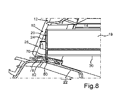
Fig. 8 the lowering of the front wall due to gravity in
such a way that a retaining
tab of the filter element formed in one piece with the front wall engages in
the retaining recess;
Fig. 9 a sectional view from the front of a cover for the
housing of the air filter
device, wherein the cover has a closure element designed as a rotary
CA 03205333 2023-7- 14
12
closure, which interacts with the fastening element of the filter element
shown in Fig. 2 in order to fix the cover;
Fig. 10 a sectional rear view of the cover in the region
of the rotary closure;
Fig. 11 a first step wherein the filter element is removed
or when the filter element
is disassembled, wherein the filter element is raised in the region of the
front wall and the retaining tab is thus moved out of the retaining recess;
Fig. 12 in a partially cross-sectional view a support web
of a plurality of support
webs of the frame sliding along ramps arranged on both sides of the
retaining recess when the filter element is pulled out of the receiving space;
Fig. 13 a perspective view of the frame of the filter
element comprising two support
webs according to Fig. 1 without a filter material of the filter element;
Fig. 14 an alternative embodiment of the fastening element
in a detail view; and
Fig. 15 an alternative embodiment of the retaining part on
the cover in a detail
view.
In the figures, identical or functionally-identical elements are provided with
the same
reference signs.
Fig. 1 shows a schematic perspective view of a filter element 10 which is
intended to be
installed in a housing 12 (cf. Fig. 3) of an air filter device of a motor
vehicle, designed in
particular as a truck. A receiving space 14 is formed in the housing 12 of the
air filter
device (cf. Fig. 3), into which the filter element 10 shown in Fig. 1 can be
introduced or
installed.
The filter element 10 comprises a frame 16 which surrounds or encloses a
filter material
18 of the filter element 10. If the filter element 10 is designed as a folded
filter, the filter
material 18 can have a plurality of folds, as exemplarily shown in the present
case.
However, other configurations of the filter material 18 through which air can
flow during
operation of the filter element 10 are also possible.
CA 03205333 2023-7- 14
13
The frame 16, which in the present case completely surrounds or encloses the
filter
material 18 on the circumferential side, comprises a front wall 20. The front
wall 20
extends perpendicularly to an insertion direction 22, which is illustrated in
Fig. 1 by an
arrow. In the insertion direction 22, the filter element 10 can be inserted
into the receiving
space 14, which is formed in the housing 12 or air filter housing (cf. Fig.
3).
A fastening element 26 is arranged on a front side 24 of the front wall 20 and
is shown
enlarged in Fig. 2. In the present case, the frame 16 also comprises two side
walls 28, 30
which extend in the insertion direction 22 starting from the front wall 20.
At its rear end, the frame 16 is closed by means of a rear wall 32, which in
the present
case is designed to be angled. This is due to the shape of the housing 12, so
that in
variants of the filter element 10 a differently designed frame 16 can also be
provided.
Furthermore, the frame 16 does not have to circumferentially enclose the
filter material 18,
as exemplarily shown in the present case.
The fastening element 26 shown in Fig. 2 serves to fix or secure a cover
element or cover
34 to the housing 12. The cover 34 is shown in Fig. 9 in a sectional view of
its outer side
36 facing the area surrounding the housing 12.
A closure element is held on a base body 38 of the cover 34, which is designed
as a
rotary closure 40 in the present case. By means of a lever-like handle part
58, the rotary
closure 40 can be rotated relative to the base body 38 of the cover 34 about
an axis of
rotation 70, which is indicated in Fig. 10. The fastening element 26 (cf. Fig.
2) interacts
with the rotary closure 40 in order to secure the cover 34 in its closed
position.
For this purpose, the fastening element 26 has a shaft 42 which in the present
case is
designed in the manner of a cylinder with an (optional) slot-shaped recess 62.
The shaft
42 projects from the front side 24 of the front wall 20 in the insertion
direction 22. Two
retaining parts in the form of a first wing 44 and a second wing 46 extend
from the shaft
42, in the present case essentially perpendicularly to the insertion direction
22.
From a respective first end region 48 towards a second, opposite end region
50, the
respective wing 44, 46 preferably has a ramp-like shape. Accordingly, the
respective wing
44, 46 increases in thickness starting from the respective first end region 48
in the
direction of a height of the respective wing 44, 46 towards the opposite end
region 50 of
the respective wing 44, 46. The height of the respective wing 44, 46 thus
corresponds to a
CA 03205333 2023-7- 14
14
thickness of the respective wing 44, 46 in the insertion direction 22. The
ramp formed on
the respective wing 44, 46 thus points in the direction of the front wall 20
of the filter
element 10.
Recesses 52 (cf. Fig. 10) correspond to the wings 44, 46 and are formed on an
inner side
54 of the cover 34 in the region of the rotary closure 40. Furthermore, the
rotary closure
40 according to Fig. 10 has two retaining parts 56 on its inner side, which
are designed to
engage behind the wings 44, 46 of the fastening element 26 when the cover 34
is secured
in its closed position, in which the cover 34 closes the receiving space 14 in
the region of
a receiving opening 64 (see Fig. 3). The filter element 10 can be introduced
into the
receiving space 14 via the receiving opening 64.
The wings 44, 46 provide clamping geometries or retaining geometries on the
side of the
filter element 10, which interact with the retaining parts 56 of the rotary
closure 40 in order
to secure the cover 34 in its closed position. In the present case, the rotary
closure 40
attached to the cover 34 therefore has the retaining parts 56 which correspond
to the
clamping geometry or retaining geometry provided by the wings 44, 46.
The fastening element 26, which is preferably firmly connected to the frame 16
of the filter
element 10 or is formed in one piece with the front wall 20, accordingly
ensures that the
cover 34 is fixed or secured in its closed position in the manner of a bayonet
lock. And in
the closed position, the cover 34 closes the receiving space 14 formed in the
housing 12
in the region of the receiving opening 64.
It can also be seen from Fig. 10 that the rotary closure 40 has a sleeve-
shaped retaining
region 66, into which the fastening element 26 can be inserted, thus closing
the cover 34.
For this purpose, the recesses 52 of the rotary closure 40 must first be
aligned in such a
way that the wings 44, 46 can enter the sleeve-shaped retaining region 66 in
the region of
the recesses 52. The retaining region 66 then encompasses the fastening
element 26. If
the rotary closure 40 is then rotated or twisted about its axis of rotation 70
by actuating the
handle part 58 (cf. Fig. 9), the retaining parts 56 of the rotary closure 40
engage behind
the wings 44, 46. Due to the ramp-like shape of the wings 44, 46, the
fastening element
26 is clamped by the rotary closure 40 of the cover 34, and the cover 34 is
pulled against
the housing 12 in order to form a tight fit.
Due to the geometry of the recesses 52 corresponding to the shape of the wings
44, 46, a
person who closes the receiving space 14 of the housing 12 by means of the
cover 34 can
CA 03205333 2023-7- 14
15
very easily visually recognize the mode of operation of the rotary closure 40.
This is
advantageous with regard to the easy operation of the rotary closure 40.
A stop 92 can be formed on the cover 34 for the handle part 58 (cf. Fig. 9),
which defines
an end position of the rotary closure 40 when the cover 34 is fixed in place.
In this end
position, the retaining parts 56 of the rotary closure 40 (cf. Fig. 10) engage
behind the
wings 44, 46 of the fastening element 26 (cf. Fig. 2).
It can also be seen from Fig. 2 that the front wall 20 has an upper narrow
side 74. In the
vertical direction 68 of the filter element 10, which is illustrated by an
arrow in Fig. 2, this
upper narrow side 74 is located opposite a lower narrow side 72 of a plate-
shaped main
body 60 of the front wall 20. The vertical direction 68 is preferably opposite
to the direction
of gravity in the installation position of the filter element 10.
In the present case, the filter element 10 has a retaining tab 76 which is
formed separately
from the fastening element 26 and is spaced apart from the fastening element
26. This
retaining tab 76 projects beyond the lower narrow side 72 of the plate-shaped
base body
60 of the front wall 20. In the present case, this retaining tab 76 is formed
in one piece
with the base body 60 of the front wall 20. The functions of this retaining
tab 76 are
explained below with reference to the following figures.
As can be seen from Fig. 3, the receiving opening 64 is delimited on the
underside by a
wall 78. In Fig. 4., this wall 78 is shown in sections and in a partially
cross-sectional view.
In particular from Fig. 4 it can be clearly seen that in the wall 78 a
retaining recess 80 is
formed, which in terms of dimensions, in this case specifically with regard to
a depth in the
insertion direction 22 and a width perpendicular to the insertion direction
22, corresponds
with the dimensions the retaining tab 76. Accordingly, the retaining tab 76 of
the filter
element 10 can be introduced into the retaining recess 80 which is provided on
the side of
the housing 12 of the air filter device. When the filter element 10 is in its
installation
position in the receiving space 14 of the housing 12 (cf. Fig. 8), the
retaining tab 76
accordingly engages in the retaining recess 80.
The retaining tab 76 or latching tab, which is formed on the lower edge of the
frame 16,
thus acts in the manner of an abutment of the filter element 10. Accordingly,
the retaining
tab 76 prevents the filter element 10 from being able to slip out of the
receiving space 14.
This is particularly advantageous when the insertion direction 22 does not
extend
CA 03205333 2023-7- 14
16
horizontally in the specific installation situation of the filter element 10,
but extends in an
inclined manner.
Furthermore, the retaining tab 76 serves to pre-fix the filter element 10 in
relation to the
cover 34. Because when the retaining tab 76 is located in the retaining recess
80, the
fastening element 26 or retention element is also aligned in the correct
position, namely
such that the rotary closure 40 (cf. Figs. 9 and 10) can interact with the
fastening element
26.
In the present case, the fastening element 26 is arranged essentially
centrally on the front
side 24 of the front wall 20 in the width or transverse direction of the front
wall 20, thus as
viewed perpendicularly to the insertion direction 22. This causes the cover 34
to be
pressed particularly evenly against the housing 12 when the rotary closure 40
is actuated
and rotated about the axis of rotation 70 in the process.
Furthermore, the two large-area ramps of the fastening element 26 formed in
the region of
the wings 44, 46 ensure a very robust fixation of the cover 34 on the filter
element 10.
The actuation of the rotary closure 40 also ensures that the front side 24 of
the retaining
tab 76 or the filter element 10 adjoining it comes to bear against retention
elements, which
in the present case are designed in the manner of ramp-like retaining teeth 82
(cf. Fig. 4),
and which are arranged upstream of the retaining recess 80 in the insertion
direction 22.
In the present case, the retaining teeth 82 slope obliquely upwards as viewed
in the
insertion direction 22, so that the retaining tab 76 initially moves in the
vertical direction 68
when sliding along the retaining teeth 82 when the filter element 10 is pushed
into the
receiving space 14 via the receiving opening 64. This insertion of the filter
element 10 into
the receiving space 14 is illustrated in Fig. 5 by an arrow 84, whose
direction is the same
as the insertion direction 22.
Fig. 6 now shows the situation in which the filter element 10 has reached its
horizontal
end position in the receiving space 14. Accordingly, the rear wall 32 of the
frame 16 is
located in the vicinity of a wall 86 of the housing 12 that delimits the
receiving space 14 to
the rear. In particular, a seal 88 arranged on the rear wall 32 of the frame
16 can bear
against the wall 86 in this regard.
CA 03205333 2023-7- 14
17
Another arrow 90 in Fig. 7 shows how, after crossing the retaining teeth 82
(cf. Fig. 4) and
reaching the retaining recess 80, the retaining tab 76 is lowered due to the
force of
gravity. Consequently, due to the force of gravity, the retaining tab 76
reaches the
retaining recess 80, which is designed in the manner of a slot. This is
because the frame
16 of the filter element 10 falls downwards due to the force of gravity as
soon as the
retaining tab 76 is at the height of the retaining recess 80 in the insertion
direction 22.
This installation situation is shown in Fig. 8, in which the retaining tab 76
engages in the
retaining recess 80. In the removal direction, i.e. counter to the insertion
direction 22, the
retaining tab 76 is undercut with the housing 12. The fastening element 26 is
then also in
its correct position, in which, after the cover 34 has been folded down or the
cover 34 has
been correspondingly pivoted about a pivot axis provided on the side of the
housing 12,
the rotary closure 40 can interact with the fastening element 26.
The removal of the filter element 10 from the receiving space 14 will be
explained with
reference to Figs. 11 and 12. First of all, the frame 16 of the filter element
10 is raised in
the region of the front wall 20 so that the retaining tab 76 is no longer
located in the
retaining recess 80. This movement of the retaining tab 76 out of the
retaining recess 80
is illustrated in Fig. 11 by an arrow 104, the direction of the arrow being
opposed to the
arrow 90 shown in Fig. 7. Otherwise, the orientation of the filter element 10
shown in Fig.
7 in relation to the housing 12 corresponds to the orientation of the filter
element 10 in
relation to the housing 12 shown in Fig. 11.
The filter element 10 is then pulled out of the receiving space 14 counter to
the insertion
direction 22. This movement is illustrated by an arrow 94 in Fig. 12.
Furthermore, a
support web 96 of the frame 16 is shown in Fig. 12 in a partially cross-
sectional view.
It can be seen from Fig. 13 that the frame 16 of the filter element 10 has two
such support
webs 96 in the present case. The support webs 96 connect the side walls 28, 30
to one
another. This stabilizes the frame 16 of the filter element 10.
In addition, the support webs 96 have a plurality of extensions designed in
the manner of
teeth 98 of a comb. These teeth 98, which project upwards or in the vertical
direction 68
from, in the present case, a strip-shaped back of the respective support web
96, engage
from below in the folds of the filter material 18 (cf Fig. 1). In this way, in
particular the teeth
98 of the support webs 96, which in the present case taper towards a free end,
support
the filter material 18. The provision of the support webs 96 and the teeth 98
ensures a
CA 03205333 2023-7- 14
18
high degree of dimensional stability of the frame 16 and in particular of the
filter material
18, even if the filter element 10 is designed to be comparatively long in the
insertion
direction 22. The latter can be the case in particular when using the filter
element 10 for
an air filter device of a truck.
The support webs 96 ensure in particular that solids that have settled on the
filter material
18 during operation of the air filter device can be easily tapped off or
shaken off the filter
material 18 without the folds of the filter material 18 being adversely
affected.
From Fig. 12, in particular when viewed together with Fig. 4, it can be
clearly seen that
when the filter element 10 is pulled out of the receiving space 14 counter to
the insertion
direction 22, an underside of the support webs 96 is guided along respective
ramps 100.
The ramps 100 thus serve as run-up slopes for the filter element 10 when the
filter
element 10 is pulled out of the receiving space 14.
In the present case, two ramps 100 are formed on the wall 78, which are
arranged
laterally next to the retaining recess 80 in the direction of longitudinal
extension of the
retaining recess 80 or in the direction of the length of the retaining recess
80 designed in
the manner of a slot (cf. Fig. 4).
Starting from an apex region 102 of the respective ramp 100, which is located
approximately at the height of a front edge of the retaining recess 80, the
ramps 100 are
designed to slope obliquely downwards as viewed in the insertion direction 22.
In the apex
region 102, the ramps 100 have a height which is greater than a maximum height
of the
retaining teeth 82 in the present case. This prevents, in particular, the
support webs 96
from catching on the retaining teeth 82 or getting caught on the retaining
teeth 82 when
the filter element 10 is pulled out of the receiving space 14 counter to the
insertion
direction 22 (cf. Fig. 12).
Furthermore, the ramps 100 are designed to slope obliquely upwards towards the
apex
region 102 as viewed in the insertion direction 22, as are the retaining teeth
82 (cf. Fig. 4).
Accordingly, the ramps 100 also prevent the filter element 10 from being able
to get
caught in the retaining teeth 82 when the filter element 10 is inserted into
the receiving
space 14.
The ramps 100 also prevent the rear wall 32 of the frame 16 from catching on
the
retaining teeth 82, in particular, when the filter element 10 is pulled out of
the receiving
CA 03205333 2023-7- 14
19
space 14, and the filter material 18 from being damaged when the filter
element 10 is
removed from the receiving space 14.
An alternative embodiment of the fastening element 26 located on the filter
element 10
and the associated closure element 40, which is arranged on the cover 34, is
shown in
Figs. 14 and 15. In contrast to Figs 2 and 10, the fastening element 26 is
designed here in
such a way that it has a sleeve-shaped retaining region 110. A retaining part
112 of the
closure element 40 which is arranged on the cover 34 is inserted into this
retaining region
110.
Here too, retaining parts 114 are provided on the fastening element 26 spaced
apart from
the front side 24, which engage behind the retaining part 112. This is
followed by a
rotation of the closure element 40 about the axis of rotation 70, as described
above, which
results in a clamping. Thus, a fixation of the filter element 10 in the
receiving space 14 and
a secure fixation of the cover 34 is achieved by an analogous geometry.
CA 03205333 2023-7- 14