Note : Les descriptions sont présentées dans la langue officielle dans laquelle elles ont été soumises.
DESCRIPTION
SEISMIC REINFORCEMENT DEVICE FOR BRIDGE
TECHNICAL FIELD
[0001]
The present invention relates to a seismic reinforcement device for a bridge,
and more specifically, relates to a seismic reinforcement device for a bridge
that has a
combination of a horizontal force sharing function and a level difference
preventive
function.
BACKGROUND ART
[0002]
Conventionally, as seismic reinforcement for reinforcing already-existing
bearings designed as the type A specified in Specifications for Highway
Bridges 2002 to
be able to withstand a level 2 earthquake motion, it has been required to
additionally
install a horizontal force sharing structure and a level difference preventive
structure.
[0003]
The horizontal force sharing structure is a seismic reinforcement structure
(device) for the already-existing bearings required from the aspect of
ensuring safety
against collapse of bridges. However, for the seismic reinforcement of the
already-existing bearings in recent years, it is required to separately
install the level
difference preventive structure in addition to the horizontal force sharing
structure so
that emergency vehicles and the like can pass even when the bearing height is
high and
thus the horizontal force sharing structure is broken by the action of a
seismic force of
level 2 earthquake motion or more (see Specifications for Highway Bridges
2012, an
administrative circular from Road Bureau of Ministry of Land, Infrastructure,
Transport
and Tourism on December 18, 2012, an administrative circular from Road Bureau
of
1
CA 03205612 2023- 7- 19
Ministry of Land, Infrastructure, Transport and Tourism on June 25, 2015, and
the like).
That is, the level difference preventive structure is required to ensure at
least a function
of an evacuation route and a transportation route for rescue, relief, medical,
and fire
fighting activities and emergency supplies as a bearing structure against the
seismic
force of level 2 earthquake motion or more.
[0004]
As the horizontal force sharing structure, for example, in Patent Document 1,
an upward lift coping type structure displacement limiting stopper device is
disclosed.
The upward lift coping type structure displacement limiting stopper device
described in
Patent Document 1 is a device provided between a substructure 6 including a
bearing
and a superstructure 7 above the substructure 6. A locking upward projection 2
is
provided on a first stopper member 1 secured to the substructure 6. A locking
downward opening depressed portion 4 is provided on a second stopper member 3
secured to the superstructure 7. The upward projection 2 is arranged in the
downward
opening depressed portion 4. A member is joined to the upper portion of the
locking
upward projection 2 on the first stopper member 1 by screw joint to provide an
outward
flange 27 projecting out laterally. An inward flange projecting out to the
inside of the
locking downward opening depressed portion 4 at a level lower than an outward
flange
27 is provided at the lower end portion of the second stopper member 3. The
width
dimension in a bridge axis-perpendicular direction of the outward flange27 is
set larger
than the width dimension between inner wall surfaces of the inward flange28
(see the
claim 1 of Patent Document 1, paragraphs [0009] to [0031] of the description,
Fig. 1
and Fig. 2 of the drawings, and the like).
[0005]
However, the upward lift coping type structure displacement limiting stopper
2
CA 03205612 2023- 7- 19
device of Patent Document 1 does not have a level difference preventive
function, and it
is necessary to provide a level difference preventive structure separately.
[0006]
As a level difference preventive structure, a level difference preventive
device
is disclosed in Patent Document 2. The level difference preventive device 1
described
in Patent Document 2 internally has a storage portion 12, has an opening 13
for adding a
filler into the storage portion 12 at an upper portion, and includes a main
body 10 that
can be secured to the upper portion of a bridge pier and a lid portion 20 that
covers the
opening 13 (see the claim 1 of Patent Document 2, paragraphs [0015] to [0022]
of the
description, Fig. 1 to Fig. 3 of the drawings, and the like).
[0007]
However, the level difference preventive device described in Patent Document
2 does not have a horizontal force sharing function, and it is necessary to
provide a
horizontal force sharing structure separately.
[0008]
As described above, both the upward lift coping type structure displacement
limiting stopper device of Patent Document 1 and the level difference
preventive device
described in Patent Document 2 are devices on the premise of being installed
individually. When there is no space around a bearing, it is necessary to
expand with a
bracket and the like from a lower structure for installing the respective
devices, which
causes a problem that the cost increases. Further, in some cases, since there
is no room
for the bracket and the like to project out from the lower structure, it is
originally
extremely difficult to make space for installing these two devices. In
addition, even
when the space for installing the two devices can be taken, the situation
around the
bearing becomes extremely complicated, which causes a problem that maintenance
and
3
CA 03205612 2023- 7- 19
management of these devices may be impeded.
[0009]
Patent Document 1: JP-A-2008-115639
Patent Document 2: JP-A-2019-138094
DISCLOSURE OF THE INVENTION
PROBLEMS TO BE SOLVED BY THE INVENTION
[0010]
Therefore, the present invention has been invented in consideration of the
above-described problems and an object of the present invention is to provide
a seismic
reinforcement device for a bridge that has a combination of a horizontal force
sharing
function and a level difference preventive function and is configured to be
installed with
a small space.
SOLUTIONS TO THE PROBLEMS
[0011]
A seismic reinforcement device for a bridge according to claim 1 is to be
added
between a substructure and a superstructure of an already-existing bridge to
increase a
seismic capacity, and the seismic reinforcement device for a bridge includes a
first
member having a projecting portion and a second member having a depressed
portion.
The seismic reinforcement device for a bridge has: a horizontal force sharing
function in
which the projecting portion and the depressed portion are freely fitted to
and engaged
with one another to constitute a shear key and resist a horizontal force by
causing the
first member to be coupled to and supported by any one of the substructure and
the
superstructure and causing the second member to be coupled to and supported by
the
4
CA 03205612 2023- 7- 19
other of the substructure and the superstructure; and a level difference
preventive
function that suppresses dropping of the superstructure and reduces a level
difference of
the substructure and the superstructure by interposing a spacer having a
predetermined
thickness between the first member and the second member or between the
substructure
or the superstructure and the seismic reinforcement device.
[0012]
In the seismic reinforcement device for a bridge according to claim 2, which
is
in the seismic reinforcement device according to claim 1, the spacer includes
a rubber
elastic body in part or is a buffer material made of a rubber elastic body in
whole.
[0013]
In the seismic reinforcement device for a bridge according to claim 3, which
is
in the seismic reinforcement device according to claim 2, the spacer
substitutes for a
part of a bearing function in an emergency.
[0014]
In the seismic reinforcement device for a bridge according to claim 4, which
is
in the seismic reinforcement device according to any one of claims 1 to 3, the
spacer is
joined to a distal end of the projecting portion.
[0015]
In the seismic reinforcement device for a bridge according to claim 5, which
is
in the seismic reinforcement device according to claim 4, the first member
includes a
disk-shaped additional flange that covers and is secured to an upper end of
the
projecting portion, and the spacer is joined to an upper surface of the
additional flange.
[0016]
In the seismic reinforcement device for a bridge according to claim 6, which
is
in the seismic reinforcement device according to claim 4, the spacer is
mechanically
CA 03205612 2023- 7- 19
fastened, adhered with an elastic adhesive, or vulcanized and adhered, to an
upper end
surface of the projecting portion.
[0017]
In the seismic reinforcement device for a bridge according to claim 7, which
is
in the seismic reinforcement device according to claim 4, includes a second
spacer
made of a rubber elastic body. The first member is mounted via the second
spacer, and
the second spacer substitutes for a part of a bearing function in an
emergency.
[0018]
In the seismic reinforcement device for a bridge according to claim 8, which
is
in the seismic reinforcement device according to claim 7, includes a rod that
restrains a
horizontal displacement of the first member is provided.
[0019]
In the seismic reinforcement device for a bridge according to claim 9, which
is
in the seismic reinforcement device according to any one of claims 1 to 8,
further
includes an upper adjusting plate according to an inclination of the
superstructure.
[0020]
In the seismic reinforcement device for a bridge according to claim 10, which
is in the seismic reinforcement device according to claim 9, the upper
adjusting plate
has a lower surface on which a depressed portion for keeping from interfering
with the
spacer is formed.
[0021]
In the seismic reinforcement device for a bridge according to claim 11, which
is in the seismic reinforcement device according to claim 4, the first member
includes a
shoulder portion projecting out to an outside, and the shoulder portion abuts
on a lower
surface of the additional flange in a state where the additional flange abuts
on an upper
6
CA 03205612 2023- 7- 19
surface of the projecting portion.
EFFECTS OF THE INVENTION
[0022]
With the seismic reinforcement device for a bridge according to the claims 1
to
11, since the horizontal force sharing function and the level difference
preventive
function can be used in combination, a narrow space around a bearing can be
effectively
utilized to reduce an installation cost. With the seismic reinforcement device
for a
bridge according to the claims 1 to 9, a seismic reinforcement device for a
bridge that
has a combination of the horizontal force sharing function and the level
difference
preventive function can be provided even when there is no room for a bracket
and the
like to project out from a lower structure. In addition, with the seismic
reinforcement
device for a bridge according to the claims 1 to 9, maintenance and management
of the
device becomes easy even in the narrow space around the bearing, and a trouble
can be
promptly discovered and dealt with.
[0023]
Especially with the seismic reinforcement device for a bridge according to the
claims 2 and 3, since the spacer is a buffer material at least including a
rubber elastic
body, a buffering effect is provided against dropping of a main girder at the
time of an
earthquake and passing by emergency vehicles, the main girder and the
substructure are
less likely to be damaged, and restorability of the bridge is improved.
[0024]
Especially with the seismic reinforcement device for a bridge according to the
claim 4, since the spacer is joined to the upper end of the projecting
portion, the spacer
does not interfere when the first member and the second member operate and
relatively
7
CA 03205612 2023- 7- 19
horizontally move, and the level difference preventive function does not
possibly hinder
the horizontal force sharing function.
[0025]
Especially with the seismic reinforcement device for a bridge according to the
claim 5, a shear force of the plate thickness of the additional flange having
a lid
structure and a dispersing function of the spacer allow for supporting a dead
load of an
upper structure, and the level difference preventive function can be exerted.
[0026]
Especially with the seismic reinforcement device for a bridge according to the
claim 6, the additional flange and the spacer can be strongly joined. In view
of this,
the dispersing function of the spacer allows for supporting the dead load of
the upper
structure, and the level difference preventive function can be exerted.
[0027]
Especially with the seismic reinforcement device for a bridge according to the
claim 7, the second spacer made of a rubber elastic body substitutes for a
part of the
bearing function in an emergency, and the dropped upper structure can be
safely
supported.
[0028]
Especially with the seismic reinforcement device for a bridge according to the
claim 8, a rod can restrain the first member from shifting in a horizontal
direction.
[0029]
Especially with the seismic reinforcement device for a bridge according to the
claim 9, the seismic reinforcement device for a bridge can be horizontally
installed
irrespective of the inclination of the superstructure.
[0030]
8
CA 03205612 2023- 7- 19
Especially with the seismic reinforcement device for a bridge according to the
claim 10, the spacer and the additional flange can be increased in thickness
to improve
the bearing function in an emergency. Further, with the seismic reinforcement
device
for a bridge according to the claim 10, even when the spacer and the
additional flange
are increased in thickness, respective members of a conventional seismic
reinforcement
device having only the horizontal force sharing function can be directly used.
In view
of this, a production cost can be reduced.
[0031]
Especially with the seismic reinforcement device for a bridge according to the
claim 11, when the superstructure drops and the level difference preventive
function is
exerted, a screw portion of the additional flange being damaged by an impact
force of
the dropping can be avoided by hooking the additional flange on the shoulder
portion.
BRIEF DESCRIPTION OF THE DRAWINGS
[0032]
Fig. 1 is a partially enlarged side view illustrating a seismic reinforcement
device for a bridge according to a first embodiment of the present invention
and a
bridge as viewed in a bridge axis-perpendicular direction.
Fig. 2 is a vertical cross-sectional view illustrating the bridge as viewed in
a
bridge axis direction in a state where the same seismic reinforcement device
for a bridge
as above and a superstructure are vertically cut off.
Fig. 3 is a vertical cross-sectional view illustrating the same seismic
reinforcement device for a bridge as above in a state of being vertically cut
off in the
bridge axis direction.
Fig. 4 are drawings illustrating only a first member of the same seismic
9
CA 03205612 2023- 7- 19
reinforcement device as above. Fig. 4A is a front view, and Fig. 4B is a plan
view.
Fig. 5 are drawings illustrating only a second member of the same seismic
reinforcement device as above. Fig. 5A is a front view, Fig. 5B is a plan
view, and Fig.
5C is a right side view.
Fig. 6 is a perspective view illustrating only an additional flange of the
same
seismic reinforcement device as above.
Fig. 7 is a perspective view illustrating only a buffer body of the same
seismic
reinforcement device as above.
Fig. 8A is a schematic diagram illustrating a state where an unbalanced load
acts on a spacer 6 and an additional flange 4 according to the embodiment, and
Fig. 8B
is a schematic diagram illustrating a state where an unbalanced load acts on a
conventional stopper device.
Fig. 9 is a partially enlarged side view illustrating a modification of a
seismic
reinforcement device for a bridge 1 according to the first embodiment of the
present
invention and a bridge as viewed in the bridge axis-perpendicular direction.
Fig. 10 is a vertical cross-sectional view illustrating a seismic
reinforcement
device for a bridge according to a second embodiment of the present invention
in a state
of being vertically cut off in the bridge axis direction.
Fig. 11 is a perspective view illustrating only an additional flange of the
same
seismic reinforcement device as above.
Fig. 12 is a vertical cross-sectional view illustrating a seismic
reinforcement
device for a bridge according to a third embodiment of the present invention
in a state
of being vertically cut off in the bridge axis direction.
Fig. 13 is a vertical cross-sectional view illustrating a seismic
reinforcement
device for a bridge according to a fourth embodiment of the present invention
in a state
CA 03205612 2023- 7- 19
of being vertically cut off in the bridge axis direction.
Fig. 14 is a vertical cross-sectional view illustrating a seismic
reinforcement
device for a bridge according to a fifth embodiment of the present invention
in a state of
being vertically cut off in the bridge axis direction.
Fig. 15 is a vertical cross-sectional view illustrating a seismic
reinforcement
device for a bridge according to a sixth embodiment of the present invention
in a state
of being vertically cut off in the bridge axis direction.
Fig. 16 is a vertical cross-sectional view illustrating a seismic
reinforcement
device for a bridge according to a seventh embodiment of the present invention
in a
state of being vertically cut off in the bridge axis direction.
Fig. 17 is a schematic diagram illustrating a structure for coping with an
uplifting force of an additional flange of a conventional stopper device.
DESCRIPTION OF PREFERRED EMBODIMENTS
[0033]
The following describes in detail a seismic reinforcement device for a bridge
according to embodiments of the present invention with reference to the
drawings.
[0034]
[First Embodiment]
First, using Fig. 1 to Fig. 8, a seismic reinforcement device for a bridge
according to a first embodiment of the present invention will be described.
The
seismic reinforcement will be described by exemplifying a case where a general
type A
bridge B1 specified in Specifications for Highway Bridges 2002 where a
concrete floor
slab Si is installed on a steel girder G2 as a superstructure G1 is reinforced
against
earthquakes to a level equal to or more than type B specified in
Specifications for
11
CA 03205612 2023- 7- 19
Highway Bridges 2002 (the same applies below).
[0035]
Fig. 1 is a partially enlarged side view illustrating a seismic reinforcement
device for a bridge 1 according to the first embodiment of the present
invention and the
bridge B1 as viewed in a bridge axis-perpendicular direction. Fig. 2 is a
vertical
cross-sectional view illustrating the bridge B1 as viewed in a bridge axis
direction in a
state where the seismic reinforcement device for a bridge 1 and the
superstructure G1
are vertically cut off. Fig. 3 is a vertical cross-sectional view illustrating
the seismic
reinforcement device for a bridge 1 in a state of being vertically cut off in
the bridge
axis direction. A reference numeral X in the drawings denotes a bridge axis
direction
X of the bridge Bl, and a reference numeral Y denotes a bridge axis-
perpendicular
direction Y of the bridge B1 (horizontal direction perpendicular to the bridge
axis
direction X). A reference numeral Z denotes an up-down direction.
[0036]
As illustrated in Fig. 1 and Fig. 2, the seismic reinforcement device for a
bridge
1 (hereinafter also simply referred to as a seismic reinforcement device 1)
according to
the first embodiment of the present invention is a seismic reinforcement
device that is
interposed between a substructure Al and the superstructure G1 of the already-
existing
bridge B1 later at the time of a reinforcement work to reinforce a seismic
capacity. In
the illustrated configuration, the seismic reinforcement device 1 is described
by
exemplifying a case where a bracket Bk made of a steel material is provided to
protrude
on a side surface of the already-existing substructure Al that is a bridge
abutment using
post-installed anchors AB and the seismic reinforcement device 1 is added on
the
bracket Bk. Surely, needless to say, when there is a space in the already-
existing
substructure Al for installing the seismic reinforcement device 1, the seismic
12
CA 03205612 2023- 7- 19
reinforcement device 1 may be directly installed in the substructure Al using
an anchor
and the like.
[0037]
As illustrated in Fig. 1 to Fig. 3, the seismic reinforcement device 1
includes a
first member 2 and a second member 3. The first member 2 is coupled to and
supported by the substructure Al via the bracket Bk, and the second member 3
is
directly coupled to and supported by the steel girder G2. With this, the
seismic
reinforcement device 1 has a horizontal force sharing function in which the
first
member 2 and the second member 3 are freely fitted and engaged to constitute a
shear
key and resist a horizontal force acting on the bridge Bl. An upper adjusting
plate 11
and a lower adjusting plate 12 are oblong metal plates, and the upper
adjusting plate 11
is tapered to level a longitudinal inclination of the steel girder G2. Surely,
needless to
say, when the superstructure is a concrete girder, the seismic reinforcement
device 1
may be installed by installing an appropriate anchor and the like.
[0038]
(First Member)
Fig. 4 are drawings illustrating only the first member 2 of the seismic
reinforcement device 1 according to the embodiment. Fig. 4A is a front view,
and Fig.
4B is a plan view. Note that a front indicates a surface of the seismic
reinforcement
device 1 illustrated in Fig. 1 as viewed along the bridge axis-perpendicular
direction Y
from the side surface of the bridge B1 (the same applies below).
[0039]
As illustrated in Fig. 4, the first member 2 is made of metal, such as a steel
material and cast iron, and in the first member 2, a rectangular (square)
plate-shaped or
a circular plate-shaped baseplate 20 and a projecting portion 21 provided to
protrude
13
CA 03205612 2023- 7- 19
facing upward in the center of the baseplate 20 are formed. The projecting
portion 21
is a projection having a truncated cone shape in which an internal corner at
the lower
end coupled to the baseplate 20 and an external corner at the upper end are
gradually
curved surfaces (round surfaces).
[0040]
The distal end (upper end) of the projecting portion 21 is a screw portion 22
in
which a screw thread is formed and to which an additional flange 4 described
below can
be screwed.
[0041]
As illustrated in Fig. 4B and Fig. 4A, a plurality of bolt holes 23 for
joining to
the bracket Bk are formed in the lower surface of the baseplate 20.
[0042]
As illustrated in Fig. 4B and Fig. 4A, a shoulder portion 24 having a diameter
larger than the outer diameter of the screw portion 22 and projecting out to
an outside in
a radial direction from a shaft core of the projecting portion 21 in a stepped
manner is
formed on the projecting portion 21 of the first member 2.
[0043]
(Second Member)
Fig. 5 are drawings illustrating only the second member 3 of the seismic
reinforcement device 1 according to the embodiment. Fig. 5A is a front view,
Fig. 5B
is a plan view, and Fig. 5C is a right side view. As illustrated in Fig. 5,
the second
member 3 is made of metal, such as a steel material and cast iron, and
configured of a
second member main body 30 having a rectangular (oblong) shape in a plan view,
a
depressed portion 31 formed in the second member main body 30, an oblong
opening
32 formed at the lower end of the depressed portion 31, and the like.
14
CA 03205612 2023- 7- 19
[0044]
As illustrated in Fig. 5A, the second member main body 30 has a tapered shape
that shrinks as going to a lower portion in the front view, in which a tapered
surface 30a
is formed. Additionally, as illustrated in Fig. 5C, the second member main
body 30 is
a rectangular-shaped framing body in a side view. Then, the depressed portion
31 that
is depressed in an oblong shape in a plan view and opened in an upper side is
formed
inside the second member main body 30. The upper portion of the second member
main body 30 may be in a plate shape, and the depressed portion 31 may be
closed at
the upper portion. Basically, it is only necessary to be able to house the
above-described projecting portion 21 in the depressed portion 31.
[0045]
As illustrated in Fig. 5A to Fig. 5C, the opening 32 having an oblong shape in
a
plan view, which is one size smaller than the depressed portion 31, is formed
in the
lower portion of the depressed portion 31. The above-described projecting
portion 21
of the first member 2 is housed inside the depressed portion 31 and the
opening 32 in a
state of being freely fitted. By being thus configured, the seismic
reinforcement device
1 has a mechanism that exerts the horizontal force sharing function that
resists a
horizontal force by causing the projecting portion 21 to abut on the opening
32 via a
buffer body 5 described below when the superstructure G1 relatively
horizontally
moves with respect to the substructure Al by an earthquake motion (see Fig.
3).
[0046]
Then, the second member main body 30 has an upper surface in which a
plurality of bolt holes 33 for joining to the steel girder G2 as the
superstructure G1 are
formed.
[0047]
CA 03205612 2023- 7- 19
(Additional Flange)
As illustrated in Fig. 3, the additional flange 4 is screwed to the
above-described screw portion 22 of the first member 2.
[0048]
Fig. 6 is a perspective view illustrating only the additional flange 4 of the
seismic reinforcement device 1 according to the embodiment. As illustrated in
Fig. 6,
the additional flange 4 is configured of a disk-shaped flange main body 40
made of
metal, such as a steel material, which covers the top of the first member 2, a
circular
depressed portion 41 formed in the center of the lower surface of the flange
main body
40, and the like.
[0049]
The circular depressed portion 41 has an inner peripheral surface on which a
thread groove 42 screwed to the screw portion 22 is formed.
[0050]
The additional flange 4 is mounted to the distal end of the projecting portion
21
by screwing the thread groove 42 to the screw portion 22 of the projecting
portion 21.
The seismic reinforcement device 1 has a mechanism that exerts the horizontal
force
sharing function that resists a horizontal force by causing the outer
peripheral end of the
additional flange 4 to abut on the depressed portion 31 when the
superstructure G1
relatively horizontally moves with respect to the substructure Al by an
earthquake
motion (see Fig. 3).
[0051]
Since only a function assumed in an additional flange 4' of a conventional
stopper device is the horizontal force sharing function and the additional
flange 4' is a
structure for coping with an uplifting force, as illustrated in Fig. 14, a
doughnut-shaped
16
CA 03205612 2023- 7- 19
object in which a hole passing through up and down is formed is screwed to the
screw
portion 22. In view of this, when a dead load on one bearing line indicated by
an
arrow A is set to 1.0, the additional flange 4' is designed so as to withstand
a force of 0.3
against an uplifting force indicated by an arrow B (see Section 13.1 Bearing
Part of
Specifications for Highway Bridges and its commentary, Part V Seismic Design,
issued
in November 2017). Fig. 17 is a schematic diagram illustrating the structure
for
coping with an uplifting force of the additional flange of the conventional
stopper
device.
[0052]
Accordingly, it is considered that, if a load is applied so as to make a
seismic
reinforcement device playing a role in a horizontal force sharing function
work simply
as a level difference preventive function, the seismic reinforcement device
cannot
withstand the load due to damage, such as breakage on parts indicated by
elongate
circles of the additional flange 4'. In view of this, the additional flange 4
according to
the embodiment is configured to be the above-described additional flange 4
that is a
threaded disk having a lid structure (cap shape) covering the top of the first
member 2
so as to play a role in a level difference preventive function in cooperation
with a spacer
6 described below.
[0053]
As described above, the shoulder portion 24 projecting out to the outside in
the
radial direction from the shaft core of the projecting portion 21 in a stepped
manner is
formed on the projecting portion 21. In view of this, in a state where the
additional
flange 4 is completely screwed to the screw portion 22 and the bottom surface
(horizontal surface) of the circular depressed portion 41 abuts on the upper
surface of
the projecting portion 21, the shoulder portion 24 abuts on the lower surface
of the
17
CA 03205612 2023- 7- 19
additional flange 4. Accordingly, when the superstructure G1 drops and the
level
difference preventive function is exerted, the screw portion 22 in the
additional flange 4
being damaged by an impact force of the dropping can be avoided by hooking the
additional flange 4 on the shoulder portion 24.
[0054]
Considering the impact force of the dropping of the superstructure GI, a
projecting-out length dl of the shoulder portion 24 from the outer peripheral
end of the
screw portion 22 to the outside illustrated in Fig. 4A is preferably 1 mm or
more
(realistically 30 mm or less taking the space into consideration), and more
preferably 7
mm or more.
[0055]
(Buffer Body)
As illustrated in Fig. 3, the tubular buffer body 5 is fitted to the outer
peripheral
surface of the projecting portion 21. The buffer body 5 is a rubber member
made of a
rubber elastic body (rubber material) which exhibits rubber elasticity at an
ordinary
temperature, such as ethylene propylene diene monomer (EPDM), chloroprene (CR)
rubber, and styrene-butadiene rubber (SBR).
[0056]
Fig. 7 is a perspective view illustrating only the buffer body 5 of the
seismic
reinforcement device 1 according to the embodiment. As illustrated in Fig. 7,
the
buffer body 5 is mainly configured of a cylindrical buffer body main body 50,
and a
tapered opening 51 that is radially expanded as going downward according to
the
truncated cone shape of the projecting portion 21 is formed on the inner
peripheral
surface of the buffer body main body 50.
[0057]
18
CA 03205612 2023- 7- 19
The buffer body 5 has a function that reduces an impact when the first member
2 abuts on the second member 3 by causing the outer peripheral surface of the
buffer
body main body 50 to abut on the opening 32 before the outer peripheral end of
the
additional flange 4 abuts on the depressed portion 31 when the superstructure
G1
relatively horizontally moves with respect to the substructure Al by an
earthquake
motion. This is to keep the seismic reinforcement device 1 from being damaged
by a
predetermined earthquake motion of about level 1. The buffer body 5 can be
omitted.
[0058]
(Spacer)
As illustrated in Fig. 3, the disk-shaped spacer 6 is adhered and joined to
the
upper end of the projecting portion 21 of the first member 2. The spacer 6
suppresses
dropping of the superstructure G1 and exerts the level difference preventive
function
that reduces a level difference on the upper surface of the superstructure G1
by its
thickness when upper bolts 9 are broken by the level 2 earthquake motion and
the
above-described horizontal force sharing function of the seismic reinforcement
device 1
is damaged.
[0059]
The spacer 6 is a disk-shaped member that is approximately identical in
diameter to the additional flange 4 and has a predetermined thickness, and in
the
embodiment, similarly to the buffer body 5, the spacer 6 is a buffer material
made of a
rubber elastic body (rubber material) which exhibits rubber elasticity at an
ordinary
temperature, such as ethylene propylene diene monomer (EPDM), chloroprene (CR)
rubber, and styrene-butadiene rubber (SBR).
[0060]
However, the spacer 6 may be made of metal, such as a steel material, and can
19
CA 03205612 2023- 7- 19
be configured of an inorganic material made of concrete, mortar, or the like,
or can be
configured of resin or the like. Basically, it is only necessary for the
spacer according
to the present invention to be configured of a material having a predetermined
compressive strength that can withstand the impact of dropping of the
superstructure
Gl.
[0061]
However, it is preferred that the spacer 6 is configured of a rubber elastic
body
(rubber material) because against the impact of dropping of the superstructure
G1 at the
time of an earthquake and even in a case where emergency vehicles pass on the
superstructure G1 after that, a buffering effect is provided, the steel girder
G2 and the
substructure Al are less likely to be damaged, and the restorability of the
bridge B1 is
improved.
[0062]
Fig. 8A is a schematic diagram illustrating a state where an unbalanced load
acts on the spacer 6 and the additional flange 4 according to the embodiment.
As
illustrated in Fig. 8A, in a case where a load acts on the proximity of the
outer edge of
the additional flange 4, configuring the spacer 6 from a rubber elastic body
(rubber
material) allows the load to be shared with the entire rubber by the
proportion of, for
example 8:2, to keep the stress from concentrating. In view of this, a shear
force of the
plate thickness of the additional flange 4 having a lid structure and a
dispersing function
of the spacer 6 made of a rubber material allow for supporting a dead load of
the upper
structure, and the level difference preventive function can be exerted.
[0063]
In contrast to this, as illustrated in Fig. 8B, only with an additional flange
made
of a conventional perforated disk without a rubber material, a load 10 that
acts on the
CA 03205612 2023- 7- 19
proximity of the outer edge of the additional flange 4' is directly applied,
and as
described above, the proximity of the screw portion 22 is highly likely to be
damaged
and broken. Fig. 8B is a schematic diagram illustrating a state where an
unbalanced
load acts on a conventional stopper device.
[0064]
The thickness of the spacer 6 is appropriately determined by the distance
between the superstructure G1 and the projecting portion 21, the distance
between the
second member 3 and the projecting portion 21, or the distance from an
interposed
object between the superstructure G1 and the second member 3 to the projecting
portion
21. Basically, the thickness of the spacer 6 is determined from
the aspect that the
spacer 6 adhered to the distal end of the projecting portion 21, the
superstructure Gl,
and the like are not in contact with respect to rotation of the superstructure
G1 at a
normal time and the above-described level difference preventive function that
suppresses the height from which the superstructure G1 drops and reduces the
level
difference can be exerted without hindering the above-described horizontal
force
sharing function.
[0065]
However, for the thickness of the spacer 6, it is preferred that the spacer 6
is
made of a rubber elastic body (rubber material) having a thickness of at least
5 mm or
more and 200 mm or less. This is because securing a predetermined thickness or
more
of the spacer 6 ensures having a function that does not only support a dead
load in an
emergency but also substitutes for a part of a bearing function for
withstanding a live
load and the like by passing vehicles to a certain extent.
[0066]
That is, the spacer 6 has a function that can counteract a load including the
21
CA 03205612 2023- 7- 19
dead load, a horizontal load caused by a temperature change, and a rotation
load caused
by an up and down motion (vibration) and the like of a girder with the
thickness of the
rubber elastic body (rubber material) as long as it is for a short period of
time and safely
support the dropped upper structure by substituting for a part of the bearing
function.
Substituting for a part of the bearing function means that, in an emergency,
such as
when the superstructure G1 drops, the bearing function to the extent that
allows
emergency vehicles and general vehicles to pass for a certain period of time
until being
restored is exerted.
[0067]
(Metal Plate)
As illustrated in Fig. 1 and Fig. 2, in the seismic reinforcement device 1,
the
first member 2 and the second member 3 are joined by bolts via metal plates 7
of a steel
material or the like. Then, in the metal plate 7, an elongate hole being long
in the
up-down direction and an elongate hole being long in the horizontal direction
are
formed, and when the seismic reinforcement device is mounted, the first member
2 and
the second member 3 are joined via the elongate holes. In view of this,
similarly to the
spacer 6, the metal plate 7 can exsert the level difference preventive
function without
hindering the above-described horizontal force sharing function by being
removed after
the seismic reinforcement device is mounted. The metal plate 7 can be omitted.
[0068]
[Modification of First Embodiment]
Next, using Fig. 9, a modification of the seismic reinforcement device for a
bridge 1 according to the first embodiment will be described. Fig. 9 is a
partially
enlarged side view illustrating the modification of the seismic reinforcement
device for
a bridge 1 according to the first embodiment of the present invention and a
bridge as
22
CA 03205612 2023- 7- 19
viewed in the bridge axis-perpendicular direction (equivalent to Fig. 1). As
illustrated
in Fig. 9, although the seismic reinforcement device 1 according to the
modification of
the first embodiment has a configuration identical to the above-described
seismic
reinforcement device 1, the top and bottom of the seismic reinforcement device
1
according to the modification is mounted invertedly with the above-described
seismic
reinforcement device 1.
[0069]
Basically, as illustrated in Fig. 9, the first member 2 is joined by bolts to
the
steel girder G2 as the superstructure Gl, and the second member 3 is joined by
bolts to
the bracket Bk provided to protrude on the side surface of the substructure
Al.
However, since other configurations are identical to those of the above-
described
seismic reinforcement device 1, detailed description thereof will be omitted.
However,
since the seismic reinforcement device 1 needs to remain on the bracket Bk
even after
an earthquake, different from a fourth embodiment described below, a weak
point needs
to be upper bolts 9' on the upper side (see also the paragraph [0065]).
[0070]
[Operational Advantage of Seismic Reinforcement Device for Bridge]
With the seismic reinforcement device for a bridge 1 according to the
embodiment of the present invention described above, since the horizontal
force sharing
function and the level difference preventive function can be used in
combination, the
seismic reinforcement device 1 can be installed with a small space, and a
narrow space
around a bearing can be effectively utilized to reduce an installation cost.
[0071]
With the seismic reinforcement device 1, since the bracket Bk and the like do
not necessarily have to project out from the substructure Al, a dual-purpose
device that
23
CA 03205612 2023- 7- 19
has a combination of the horizontal force sharing function and the level
difference
preventive function can be provided even when there is no room for the bracket
Bk and
the like to project out from the substructure Al.
[0072]
In addition, with the seismic reinforcement device 1, maintenance and
management of the device becomes easy even in the narrow space around the
bearing,
and a trouble can be promptly discovered and dealt with.
[0073]
Furthermore, with the seismic reinforcement device 1, since the spacer 6 is a
buffer material made of a rubber elastic body, the steel girder G2 as a main
girder and
the substructure Al are less likely to be damaged even in a case where
emergency
vehicles pass on the seismic reinforcement device 1 in which the horizontal
force
sharing function is damaged and a small level difference is generated. In view
of this,
the restorability of the bridge B1 is improved. With the seismic reinforcement
device
1, configuring the spacer 6 from a rubber elastic body (rubber material)
allows the load
to be shared with the entire rubber to keep the stress from concentrating. In
view of
this, a shear force of the plate thickness of the additional flange 4 having a
lid structure
and a dispersing function of the spacer 6 made of a rubber material allow for
supporting
a dead load of the upper structure, and the level difference preventive
function can be
exerted.
[0074]
In addition to that, with the seismic reinforcement device 1, since the spacer
6
is joined to the distal end of the projecting portion 21, the spacer 6 does
not interfere
when the first member 2 and the second member 3 operate and relatively
horizontally
move, and the level difference preventive function does not possibly hinder
the
24
CA 03205612 2023- 7- 19
horizontal force sharing function.
[0075]
[Second Embodiment]
Next, using Fig. 10 and Fig. 11, a seismic reinforcement device for a bridge
1'
(hereinafter also simply referred to as the seismic reinforcement device 1')
according to
a second embodiment of the present invention will be described. Fig. 10 is a
vertical
cross-sectional view illustrating the seismic reinforcement device for a
bridge 1'
according to the second embodiment of the present invention in a state of
being
vertically cut off in the bridge axis direction (equivalent to Fig. 3). Fig.
11 is a
perspective view illustrating only the additional flange 4' of the seismic
reinforcement
device 1'. Since a point in which the seismic reinforcement device l' differs
from the
above-described seismic reinforcement device 1 is mainly an installation
position of a
spacer 6', the point will be described. Other identical configurations are
denoted by
identical reference numerals, and the description thereof will be omitted.
[0076]
The spacer 6' of the seismic reinforcement device 1' is a buffer material made
of a rubber elastic body (rubber material). As illustrated in Fig. 10, the
spacer 6' is
placed on a rectangular-shaped (square-shaped) plate 8 made of a steel plate
or the like
that is one size larger than the baseplate 20 that is joined to the above-
described first
member 2 to be integrated with the first member 2. Surely, similarly to the
spacer 6,
the spacer 6' may also be made of metal, such as a steel material, and can be
configured
of an inorganic material made of concrete, mortar, or the like, or can be
configured of
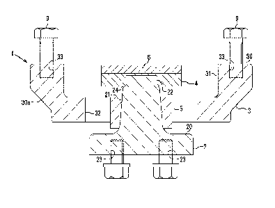
resin or the like.
[0077]
The spacer 6' is a doughnut-shaped or rectangular-shaped member having an
CA 03205612 2023- 7- 19
inner diameter that is one size larger than the baseplate 20 of the first
member 2. The
inner diameter does not hinder relative horizontal movement of the first
member 2 and
the second member 3 that operate as the horizontal force sharing function.
[0078]
Since the additional flange 4' does not directly play a role in the level
difference preventive function and does not receive a load, as illustrated in
Fig. 11,
similarly to a conventional additional flange, the additional flange 4' is
configured of a
perforated disk-shaped flange main body 40' made of metal, such as a steel
material, a
circular opening 41' formed in the center of the lower surface of the flange
main
body40', and the like. The circular opening 41' has an inner peripheral
surface on
which a thread groove 42' screwed to the above-described screw portion 22 is
formed.
[0079]
With the seismic reinforcement device for a bridge l' according to the second
embodiment of the present invention, similarly to the seismic reinforcement
device 1,
since the horizontal force sharing function and the level difference
preventive function
can be used in combination, the seismic reinforcement device l' can be
installed with a
small space, and a narrow space around a bearing can be effectively utilized
to reduce
an installation cost.
[0080]
[Third Embodiment]
Next, using Fig. 12, a seismic reinforcement device for a bridge 1"
(hereinafter
also simply referred to as a seismic reinforcement device 1") according to a
third
embodiment of the present invention will be described. Fig. 12is a vertical
cross-sectional view illustrating the seismic reinforcement device for a
bridge 1"
according to the third embodiment of the present invention in a state of being
vertically
26
CA 03205612 2023- 7- 19
cut off in the bridge axis direction (equivalent to Fig. 3). Since only a
point in which
the seismic reinforcement device 1" differs from the above-described seismic
reinforcement device l' is an installation position of a spacer 6", the point
will be
described. Other identical configurations are denoted by identical reference
numerals,
and the description thereof will be omitted.
[0081]
The spacer 6" of the seismic reinforcement device 1" is a buffer material made
of a rubber elastic body (rubber material), and as illustrated in Fig. 11, is
placed on the
baseplate 20 of the above-described first member 2. Surely, the spacer 6"may
be made
of metal, such as a steel material, and can be configured of an inorganic
material made
of concrete, mortar, or the like, or can be configured of resin or the like.
[0082]
The spacer 6" is a doughnut-shaped or rectangular-shaped member having an
inner diameter that is one size larger than the baseplate 20 of the first
member 2. The
inner diameter does not hinder relative horizontal movement of the first
member 2 and
the second member 3 that operate as the horizontal force sharing function.
[0083]
With the seismic reinforcement device for a bridge 1" according to the third
embodiment of the present invention, similarly to the seismic reinforcement
device 1,
since the horizontal force sharing function and the level difference
preventive function
can be used in combination, the seismic reinforcement device 1" can be
installed with a
small space, and a narrow space around a bearing can be effectively utilized
to reduce
an installation cost.
[0084]
[Fourth Embodiment]
27
CA 03205612 2023- 7- 19
Next, using Fig. 13, a seismic reinforcement device for a bridge 10
(hereinafter
also simply referred to as a seismic reinforcement device 10) according to a
fourth
embodiment of the present invention will be described. Fig. 13 is a vertical
cross-sectional view illustrating the seismic reinforcement device for a
bridge 10
according to the fourth embodiment of the present invention in a state of
being
vertically cut off in the bridge axis direction. A point in which the seismic
reinforcement device 10 differs from the above-described seismic reinforcement
device
1 is mainly a point in which the additional flange 4' is a conventional
perforated
disk-shaped flange. Accordingly, other identical configurations are denoted by
identical reference numerals, and the description thereof will be omitted.
[0085]
It is considered that, if a load is applied so as to cause a seismic
reinforcement
device playing a role in the horizontal force sharing function to work simply
as the level
difference preventive function, the seismic reinforcement device cannot
withstand the
load due to damage, such as breakage on parts indicated by elongate circles of
the
additional flange. In view of this, a spacer 60 according to the embodiment is
made
larger and thicker than the above-described spacer 6 and is mechanically
secured to the
additional flange 4' by screwing screws B2 and the like to compensate for the
lack of
adhesive strength with the additional flange 4'. However, joining of the
spacer 60 to
the additional flange 4' is not limited to securing by screwing, and both may
be joined
so as to be mechanically fastened by providing a lock piece with which any one
of the
additional flange 4' and the spacer 60 is hooked to the other or both.
[0086]
Similarly to the spacer 6, the spacer 60 according to the embodiment is a
buffer
material made of a rubber elastic body (rubber material). Surely, similarly to
the
28
CA 03205612 2023- 7- 19
spacer 6, the spacer 60 may also be made of metal, such as a steel material,
and can be
configured of an inorganic material made of concrete, mortar, or the like, or
can be
configured of resin or the like.
[0087]
It is also considered that the spacer 60 according to the embodiment is not
mechanically secured to the additional flange 4' by screwing, but adhesion
(for example,
adhesion with an elastic adhesive with a satisfactory adhesiveness with a
rubber elastic
body which flexibly absorbs and disperses stress applied from an inside and
outside to a
joint portion) is performed using an adhesive that allows a strong adhesion to
the
additional flange 4' to increase the adhesive strength and vulcanization
bonding is
performed by applying heat and pressure to the additional flange 4'.
[0088]
With the seismic reinforcement device for a bridge 10 according to the fourth
embodiment of the present invention, similarly to the seismic reinforcement
device 1,
since the horizontal force sharing function and the level difference
preventive function
can be used in combination, the seismic reinforcement device 10 can be
installed with a
small space, and a narrow space around a bearing can be effectively utilized
to reduce
an installation cost.
[0089]
[Fifth Embodiment]
Next, using Fig. 14, a seismic reinforcement device for a bridge 13
(hereinafter
also simply referred to as a seismic reinforcement device 13) according to a
fifth
embodiment of the present invention will be described. Fig. 14 is a vertical
cross-sectional view illustrating the seismic reinforcement device for a
bridge 13
according to the fifth embodiment of the present invention in a state of being
vertically
29
CA 03205612 2023- 7- 19
cut off in the bridge axis direction. A point in which the seismic
reinforcement device
13 differs from the above-described seismic reinforcement device 1 is mainly a
point in
which, in addition to the spacer 6, a second spacer 61 is interposed between
the first
member 2 and the plate 8. Accordingly, other identical configurations are
denoted by
identical reference numerals, and the description thereof will be omitted.
[0090]
The second spacer 61 of the seismic reinforcement device 13 is a buffer
material made of a rubber elastic body (rubber material) having a thickness of
at least 5
mm or more and 200 mm or less, and as illustrated in Fig. 14, is interposed
between the
baseplate 20 of the first member 2 and the plate 8. The second spacer 61 is a
rectangular-shaped member having an area similar to that of the baseplate 20
of the first
member 2 in a plan view and has a function that does not only support a dead
load in an
emergency but also substitutes for a part of a bearing function for
withstanding a live
load and the like by passing vehicles to a certain extent.
[0091]
That is, the second spacer 61 has a function that can counteract a load
including the dead load, a horizontal load caused by a temperature change, and
a
rotation load caused by an up and down motion (vibration) and the like of a
girder with
the thickness of the rubber elastic body (rubber material) as long as it is
for a short
period of time and safely support the dropped upper structure by substituting
for a part
of the bearing function. Substituting for a part of the bearing function means
that, in
an emergency, such as when the superstructure G1 drops, the bearing function
to the
extent that allows emergency vehicles and general vehicles to pass for a
certain period
of time until being restored is exerted.
[0092]
CA 03205612 2023- 7- 19
With the seismic reinforcement device for a bridge 13 according to the fifth
embodiment of the present invention, similarly to the seismic reinforcement
device 1,
since the horizontal force sharing function and the level difference
preventive function
can be used in combination, the seismic reinforcement device 13 can be
installed with a
small space, and a narrow space around a bearing can be effectively utilized
to reduce
an installation cost.
[0093]
In addition, with the seismic reinforcement device 13, the second spacer 61
made of a rubber elastic body substitutes for a part of the bearing function
in an
emergency, such as when the superstructure G1 drops by an earthquake, and the
dropped upper structure can be safely supported.
[0094]
[Sixth Embodiment]
Next, using Fig. 15, a seismic reinforcement device for a bridge 14
(hereinafter
also simply referred to as a seismic reinforcement device 14) according to a
sixth
embodiment of the present invention will be described. Fig. 15 is a vertical
cross-sectional view illustrating the seismic reinforcement device for a
bridge 14
according to the sixth embodiment of the present invention in a state of being
vertically
cut off in the bridge axis direction. Points in which the seismic
reinforcement device
14 differs from the above-described seismic reinforcement device 13 are mainly
a point
in which a baseplate 20' of the first member 2 and a second spacer 62 have an
area
larger than that of the above-described baseplate 20 and the second spacer 61
and a
point in which a rod 15 is provided. Accordingly, other identical
configurations are
denoted by identical reference numerals, and the description thereof will be
omitted.
[0095]
31
CA 03205612 2023- 7- 19
The second spacer 62 of the seismic reinforcement device 14 is a buffer
material made of a rubber elastic body (rubber material) having a thickness of
about 5
mm, and as illustrated in Fig. 15, is interposed between the baseplate 20' of
the first
member 2 and the plate 8. Similarly to the second spacer 61, the second spacer
62 is a
rectangular-shaped member having an area similar to that of the baseplate 20'
of the first
member 2 in a plan view and has a function that does not only support a dead
load in an
emergency but also substitutes for a part of a bearing function for
withstanding a live
load and the like by passing vehicles to a certain extent.
[0096]
The baseplate 20' of the first member 2 and the second spacer 62 of the
seismic
reinforcement device 14 has an area of 1.3 times or more the area of the
above-described baseplate 20 and the spacer 61 in a plan view, and increasing
the area
of the second spacer 62 reduces a load that can be supported per unit area and
improves
a load bearing capacity. This improves a substitutability of the bearing
function by the
second spacer 62 and improves the load bearing capacity.
[0097]
As illustrated in Fig. 15, the rod 15 is provided in the seismic reinforcement
device 14. The rod 15 is fixedly secured by screwing, welding, or the like to
and
provided upright on the plate 8 or the bracket Bk and has a function that
restrains the
baseplate 20' from shifting in the horizontal direction. This is to keep the
second
spacer 62 made of a rubber elastic body from deforming by a temperature change
of the
bridge main body and becoming unable to support a vertical load. The rod 15
can be
substituted by thickening bolts to fasten the first member 2.
[0098]
With the seismic reinforcement device for a bridge 14 according to the sixth
32
CA 03205612 2023- 7- 19
embodiment of the present invention, similarly to the seismic reinforcement
device 1,
since the horizontal force sharing function and the level difference
preventive function
can be used in combination, the seismic reinforcement device 14 can be
installed with a
small space, and a narrow space around a bearing can be effectively utilized
to reduce
an installation cost.
[0099]
Further, with the seismic reinforcement device 14, the second spacer 62 made
of a rubber elastic body substitutes for a part of the bearing function in an
emergency,
such as when the superstructure G1 drops by an earthquake, and the dropped
upper
structure can be safely supported.
[0100]
In addition, with the seismic reinforcement device 14, since the
superstructure
G1 is supported by the second spacer 62 made of a rubber elastic body having
an area of
1.3 times or more the area of the second spacer 61, the load that can be
supported per
unit area can be reduced, and the load bearing capacity is improved. In
addition to that,
the seismic reinforcement device 14 restrains the baseplate 20' from shifting
in the
horizontal direction by the rod 15, and the horizontal force sharing function
of the
seismic reinforcement device 14 is not impaired by the second spacer 62.
[0101]
[Seventh Embodiment]
Next, using Fig. 16, a seismic reinforcement device for a bridge 16
(hereinafter
also simply referred to as a seismic reinforcement device 16) according to a
seventh
embodiment of the present invention will be described. Fig. 16 is a vertical
cross-sectional view illustrating the seismic reinforcement device for a
bridge 16
according to the seventh embodiment of the present invention in a state of
being
33
CA 03205612 2023- 7- 19
vertically cut off in the bridge axis direction. Points in which the seismic
reinforcement device 16 differs from the above-described seismic reinforcement
device
1 are mainly a point in which an upper adjusting plate 11' is provided and a
point in
which a depressed portion 110' is formed in the upper adjusting plate 11'.
Accordingly,
other identical configurations are denoted by identical reference numerals,
and the
description thereof will be omitted.
[0102]
As illustrated in Fig. 16, the seismic reinforcement device 16 includes the
upper adjusting plate 11' in which a tapered surface (inclined surface)
according to the
longitudinal inclination of the steel girder G2 is formed. Similarly to the
above-described upper adjusting plate 11, the upper adjusting plate 11' is a
member that
is interposed between the steel girder G2 and the second member 3 to level the
longitudinal inclination of the steel girder G2 for horizontally installing
the first
member 2 and the second member 3.
[0103]
The depressed portion 110' is provided on the lower surface of the upper
adjusting plate 11' of the seismic reinforcement device 16 according to the
embodiment.
The depressed portion 110' is a depressed portion to keep a spacer 60' from
coming into
contact with the upper adjusting plate 11' and interfering at the time of
horizontal
movement so that the horizontal force sharing function of the seismic
reinforcement
device 16 does not become impaired.
[0104]
The spacer 60' is a buffer material made of a rubber elastic body (rubber
material) having a thickness of about 20 mm and can improve the
substitutability of the
bearing function in an emergency by increasing the thickness from that of the
34
CA 03205612 2023- 7- 19
above-described spacer 6.
[0105]
For an additional flange 4", the thickness of a part covering the second
member
3 is increased from that of the above-described additional flange 4 to
increase the
strength that can withstand the impact when the superstructure G1 drops.
[0106]
However, for the seismic reinforcement device 16, regardless of increased
thicknesses of the spacer 60' and the additional flange 4", respective members
of a
conventional seismic reinforcement device having only the horizontal force
sharing
function can be directly used for other members, such as the first member 2
and the
second member 3. In view of this, conventional manufacturing equipment can be
directly used, and a production cost can be reduced.
[0107]
With the seismic reinforcement device for a bridge 16 according to the seventh
embodiment of the present invention, similarly to the seismic reinforcement
device 1,
since the horizontal force sharing function and the level difference
preventive function
can be used in combination, the seismic reinforcement device 16 can be
installed with a
small space, and a narrow space around a bearing can be effectively utilized
to reduce
an installation cost.
[0108]
Further, with the seismic reinforcement device 16, the spacer 60' made of a
rubber elastic body substitutes for a part of the bearing function in an
emergency, such
as when the superstructure G1 drops by an earthquake, the dropped upper
structure can
be safely supported, and also the production cost can be reduced.
[0109]
CA 03205612 2023- 7- 19
While the seismic reinforcement devices for a bridge 1, l', 1", 10, 13, 14,
and
16 according to the first to seventh embodiments of the present invention have
been
described in detail above, any of the above-described or illustrated
embodiments is
merely one embodiment embodied in carrying out the present invention.
Accordingly,
the technical scope according to the present invention should not be construed
in a
limited manner by these.
[0110]
In particular, the spacer according to the present invention is not limited to
those of the exemplified first to seventh embodiments and may be provided
between the
upper adjusting plate 11 and the second member 3 illustrated in Fig. 1 and
Fig. 2,
between the upper adjusting plate 11 and the superstructure G1 , between the
first
member 2 and the lower adjusting plate 12, or between the lower adjusting
plate 12 and
the bracket Bk and/or substructure Al. Basically, it is only necessary to
provide the
spacer according to the present invention between the first member 2 and the
second
member 3 or between the substructure Al or the superstructure G1 and the
seismic
reinforcement device 1.
DESCRIPTION OF REFERENCE SIGNS
[0111]
1, l', 1", 10, 13, 14, 16:Seismic reinforcement device (Seismic reinforcement
device for
a bridge)
2: First member
20, 20': Baseplate
21: Projecting portion
22: Screw portion
36
CA 03205612 2023- 7- 19
23: Bolt hole
24: Shoulder portion
3: Second member
30: Second member main body
30a: Tapered surface
31: Depressed portion
32: Opening
33: Bolt hole
4, 4', 4": Additional flange
40, 40': Flange main body
41: Circular depressed portion
41': Circular opening
42, 42': Thread groove
5: Buffer body
50: Buffer body main body
51: Tapered opening
6, 6', 6", 60, 60': Spacer
61, 62: Second spacer
7: Metal plate
8: Plate
9,9': Upper bolt
11, 11': Upper adjusting plate
12: Lower adjusting plate
15: Rod
B1 : Bridge
37
CA 03205612 2023- 7- 19
Gl: Superstructure
G2: Steel girder (Superstructure)
Al: Substructure
Bk: Bracket
Si: Concrete floor slab
AB: Post-installed anchor
B2: Screw
38
CA 03205612 2023- 7- 19