Note : Les descriptions sont présentées dans la langue officielle dans laquelle elles ont été soumises.
INFRARED TEMPERATURE MEASUREMENT AND STABILIZATION THEREOF
CROSS-REFERENCE TO RELATED APPLICATIONS
100011 This application claims priority to U.S. Non-provisional Patent
Application,
Serial No. 14/281,334 entitled "INFRARED TEMPERATURE MEASUREMENT AND
STABILIZATION THEREOF", filed on May 19,2014, which is a continuation-in-part
(CIP)
and claims priority to U.S. Non-Provisional Patent Application, Serial No.
13/178,077
entitled "INFRARED TEMPERATURE MEASUREMENT AND STABILIZATION
THEREOF", filed on July 7, 2011 which claims the benefit of U.S. Provisional
Patent
Application, Serial No. 61/362,623 entitled "INFRARED TEMPERATURE
MEASUREMENT AND STABILIZATION THEREOF", filed on July 8, 2010.
BACKGROUND
[0002] Infrared (IR) temperature sensors can monitor infrared light which
is then
converted into an electrical signal and ultimately to a temperature reading.
The spectrum
of infrared radiation cannot be readily seen by humans without the use of
specially
designed equipment that makes the spectrum visible. Measurement of infrared
waves is
calibrated in microns, ranging from 0.7 to 1000 microns. Today, infrared
temperature
sensors can be used to measure temperature of almost any type of moving part
or object,
including many used related to vehicles.
[0003] One of the most basic IR temperature sensor designs consists of a
lens that
focuses IR energy onto to a detector. The detector can convert the measured
energy to
an electrical signal, which can be displayed in units of temperature. An
object's emissivity
is used together with the captured energy in order to convert measured energy
into
temperature. Today, more sophisticated sensors can passively compensate for
ambient
temperature variations so as to effect accurate measurement of a target
object.
[0004] One very useful feature of IR sensors is the ability to measure
1
Date Regue/Date Received 2023-07-14
temperatures, e.g., without physical contact. This temperature monitoring
ability is
especially useful in situations where objects are in motion, e.g., in
vehicular
applications. Unfortunately, environmental effects upon the sensor require
protective
housings and the like to be installed to protect the sensors from
environmental
elements. Protective housings and the like indude materials that vary in
temperature
and contribute to the IR energy path of the sensor thereby making accurate and
efficient temperature measurements difficult.
[0005] With regard to conventional IR temperature sensors, significant
measurement errors often occur when the IR sensor, e.g., thermopile, is
subject
to thermal conditions such as a wide range in operating temperatures,
temperature rate of change, or static thermal gradients in the sensing region
or
path. Any IR visible object in the path between the sensing component and the
measurement target will both deliver energy to the sensor as well as block a
portion of the thermal energy emitted by object target; resulting in accurate
and
inefficient temperature measurement.
BRIEF DESCRIPTION
[0006] This brief description is provided to introduce a selection of
concepts
in a simplified form that are described below in the detailed description.
This
brief description is not intended to be an extensive overview of the claimed
subject matter, identify key factors or essential features of the claimed
subject
matter, nor is it intended to be used to limit the scope of the claimed
subject
matter.
[0007] According to one or more aspects, one or more embodiments
include
infrared (IR) temperature measurement and stabilization systems, and methods
related thereto. One or more embodiments actively stabilizes temperatures of
objects in the path between an IR sensor and target object. A temperature
monitor and controller is employed to regulate power to resistive temperature
devices (RTDs) thereby regulating current (and power) to the RTDs. As a
result, temperatures of IR visible objects can be actively stabilized for
changes,
for example, changes in ambient temperatures.
[0008] With regard to traditional infrared (IR) temperature sensors,
2
Date Recue/Date Received 2023-07-14
significant measurement errors often occur when the IR sensor, e.g.,
thermopile, is subject
to thermal conditions such as a wide range in operating temperature,
temperature rate of
change, or static thermal gradients in the sensing region. IR visible objects
in the path
between the sensing component and the measurement target will both deliver
energy to the
sensor as well as block a portion of the thermal energy emitted by object
target. In
accordance with one or more aspects, intermediate media, such as optical lens
and
protective window, are held thermally stable thereby allowing their energy
contributions to
be known and precisely compensated for by the measurement system. As well,
other
components in the sensing region can be stabilized via RTDs, e.g., sensor
housing,
baseplate, etc.
[0009]
Accordingly, one or more aspects can deliver a final temperature indication
response time that is significantly reduced by actively stabilizing the key
measurement
components. Temperature compensation, including both sensor steady-state
temperature
and rate of change dependencies, can be significantly reduced or eliminated by
actively
stabilizing the key measurement components by way of RTDs together with
temperature
control components and circuitry.
[0010]
In other aspects, passive stabilization of temperatures of objects in a path
between a sensor and a target object is provided. In these aspects passive
thermal
stabilization is accomplished via conductively coupling the sensor to optics.
[0010a]
In one aspect, an infrared (IR) temperature monitoring system, comprising: a
protective housing having an open end and a closed end, the protective housing
having a
transmissive window defined on a surface of the closed end; an IR element
including a
temperature sensor having a sensor housing, wherein the protective housing
covers the IR
element; and a frame having a flange at one end and being configured to
receive the IR
element in an end opposite that of the flange, wherein the flange of the frame
has an outer
diameter that is substantially the same as an inner diameter of the protective
housing, and
wherein the frame is positioned inside the protective housing such that the
outer diameter
of the flange is snug against the inner diameter of the protective housing and
the flange is
in contact with the surface of the closed end of the protective housing such
that the flange
encompasses the transmissive window defined in the closed end of the
protective housing.
3
Date Recue/Date Received 2023-07-14
10010b1 In another aspect, a method for infrared (IR) temperature monitoring,
comprising:
covering an IR element of an IR temperature sensor with a sensor housing;
covering the IR
element with a protective housing having an open end, a closed end, the
protective housing
having a transmissive window defined on a surface of the closed end; and
positioning a
frame having a flange at one end and being configured to receive the IR
element in an end
opposite that of the flange, wherein the flange of the frame has an outer
diameter that is
substantially the same as an inner diameter of the protective housing, and
wherein the frame
is positioned inside the protective housing such that the outer diameter of
the flange is snug
against an inner diameter of the protective housing and the flange is in
contact with the
closed end of the protective housing such that the flange frames the
transmissive window in
the closed end of the protective housing.
[0010c] In another aspect, an infrared (IR) temperature monitoring system,
comprising: a
protective housing having an open end, a closed end, and a transmissive window
define on
a surface of the closed end; an IR temperature sensor having a sensor housing
which covers
an IR element, wherein the protective housing covers the IR temperature sensor
and the
sensor housing; a frame having a flange at one end and being configured to
receive the IR
element in an end opposite that of the flange, wherein the flange of the frame
has an outer
diameter that is substantially the same as an inner diameter of the protective
housing, and
wherein the metallic frame is positioned inside the protective housing such
that the outer
diameter of the flange is snug against the inner diameter of the protective
housing and the
flange is in contact with the closed end of the protective housing such that
the flange frames
the transmissive window in the closed end of the protective housing; and a
protective
housing plug configured to fit in the open end of the protective housing to
complete an
internal system seal impervious to one or more environmental effects.
[0010d] In another aspect, an infrared (IR) temperature monitoring system,
comprising: a
protective housing having an open end and closed end, wherein the protective
housing is
plastic; an IR temperature sensor element (sensor element) having a protective
sensor
housing which covers an IR element, wherein the protective housing covers the
sensor
element and the sensor housing, wherein the protective housing is a cap that
shields the
sensor element from one or more environmental effects; and a frame positioned
upon an
inner portion of the closed end of the protective housing, the frame
encompasses a
3a
Date Recue/Date Received 2023-07-14
transmissive window in the closed end of the protective housing, wherein the
frame is a
conductive top hat, wherein the conductive top hat establishes a stable
thermal link between
the transmissive window and the sensor element.
[0010e] In another aspect, a method for infrared (IR) temperature monitoring,
comprising:
covering a sensor element with a protective housing; covering the sensor
element with a
protective housing having an open end and closed end, wherein the protective
housing is a
cap that shields the sensor element from one or more environmental effects,
wherein the
protective housing is plastic; and positioning a frame upon an inner portion
of the closed end
of the protective housing, wherein the frame encompasses a transmissive window
in the
closed end of the protective housing, wherein the frame is a conductive top
hat.
1001011 In another aspect, an infrared (IR) temperature monitoring system,
comprising: a
protective housing having an open end and closed end; an IR temperature sensor
having a
sensor housing which covers an IR element, wherein the protective housing
covers the IR
temperature sensor and the sensor housing, wherein the protective housing is a
plastic cap
that shields the sensor housing and the IR temperature sensor from one or more
environmental effects; a frame positioned upon an inner portion of the closed
end of the
protective housing, wherein the frame encompasses a transmissive window in the
closed
end of the protective housing; and a housing plug to complete an internal
system seal
impervious to one or more of the environmental effects, wherein the IR
temperature sensor
is actively stabilized using temperature control components, including
resistive temperature
devices, and circuitry.
[0011] The following description and annexed drawings set forth certain
illustrative
aspects and implementations. These are indicative of but a few of the various
ways in which
one or more aspects may be employed. Other aspects, advantages, or novel
features of
the disclosure will become apparent from the following detailed description
when considered
in conjunction with the annexed drawings.
BRIEF DESCRIPTION OF THE DRAWINGS
[0012] Aspects of the disclosure are understood from the following detailed
description
when read with the accompanying drawings. Elements, structures,
3b
Date Recue/Date Received 2023-07-14
etc. of the drawings may not necessarily be drawn to scale. Accordingly, the
dimensions of the same may be arbitrarily increased or reduced for clarity of
discussion, for example.
[0013] Fig. 1 is an illustration of an example infrared (IR)
temperature sensor
system capable of component stabilization, according to one or more
embodiments.
[01114] Fig. 2 is an illustration of an example bottom view of a self-
heating
temperature sensor system, according to one or more embodiments.
[0015] Fig. 3 is an illustration of an example top-down view of a self-
heating
temperature sensor system, according to one or more embodiments.
[(8)16] Fig. 4 is an illustration of an example electrical schematic of
components and circuitry that facilitate temperature stabilization, according
to
one or more embodiments.
[0017] Fig. 5 is an illustration of an example method for facilitating
active
temperature stabilization, according to one or more embodiments.
[0018] Fig. 6 is an illustration of an example self-heating
temperature IR
sensor assembly, according to one or more embodiments.
[0019] Fig. 7 is an illustration of an example exploded view of an
example
sensor assembly, according to one or more embodiments.
[0020] Fig. 8 is an illustration of an example bottom perspective view
of an
example sensor assembly, according to one or more embodiments.
[0021] Fig. 9 is an illustration of an example side perspective view
of an
example sensor assembly, according to one or more embodiments.
[0022] Fig. 10 is an illustration of an example bottom-up perspective
view of
an example sensor assembly, according to one or more embodiments.
[0023] Fig. 11 is an illustration of yet another example perspective
view of
an assembly, according to one or more embodiments.
[0024] Fig. 12 is an illustration of an example placement of a
conductive
frame, according to one or more embodiments.
[0025] Fig. 13 is an illustration of an example side perspective view
of a
4
Date Recue/Date Received 2023-07-14
protective housing and circuit board base, according to one or more
embodiments.
[0026] Fig. 14 is an illustration of an example conductive frame,
according
to one or more embodiments.
[0027] Fig. 15 is an illustration of glass fillers positioned onto
leads,
according to one or more embodiments.
[0028] Fig. 16 is an example bottom-up perspective view of an
assembly,
according to one or more embodiments.
[0029] Fig. 17 is an illustration of an example infrared (IR)
temperature
monitoring system, according to one or more embodiments.
DETAILED DESCRIPTION
[0030] Embodiments or examples, illustrated in the drawings are
disclosed
below using specific language. It will nevertheless be understood that the
embodiments or examples are not intended to be limiting. Any alterations and
modifications in the disclosed embodiments, and any further applications of
the
principles disclosed in this document are contemplated as would normally occur
to one of ordinary skill in the pertinent art.
[0031] As will be described in greater detail infra, one or more
embodiments
provides for stabilization of critical measurement components as well as other
'visible' objects in an infrared (IR) temperature measurement system. One or
more embodiments can effectively stabilize interference caused by a protective
cap or housing as well as other IR 'visible components in close proximity to
the
IR sensor. As will be understood, IR thermal measurement is highly susceptible
to the thermal energy state and flux of both the sensing element and IR
'visible'
media in (and around) the target-object path. Active stabilization of the
thermal
energy or absolute temperature of these system components is one underlying
principal of this disclosure. This temperature stabilization enhances accuracy
and can be performed at an efficient rate as compared to conventional IR
sensor systems.
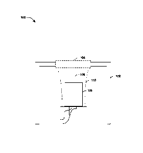
[0032] Referring initially to the drawings, Fig. 1 illustrates an
example IR
Date Regue/Date Received 2023-07-14
temperature sensor system 100 capable of active component temperature
stabilization. Generally, the system 100 can include a protective housing 102
(e.g., molded plastic cap) having an integral window or lens 104. It will be
appreciated that the lens 104 (e.g., transparent window) enables measurement
of IR energy via IR temperature sensor 106 (e.g., thermopile). It will be
appreciated that this window can be manufactured of the same material as the
protective housing 102. Thus, variations in temperature of the window 104
effects accuracy of IR measurements until its temperature is stabilized. It
will
be appreciated that the window 104 can often represent 30 to 50% of the energy
detected by thermopile 106. For at least this reason, one or more embodiments
is capable of stabilizing the temperature of the window 104 such that
compensation can efficiently and effectively be made to enhance accuracy of
the sensing device 106. As shown, the temperature sensor 106 is equipped
with optics 108, which can also vary in temperature and effect performance of
the thermopile 106.
[0033] Because the temperature of the window 104 fluctuates often
during
operation, a heat source is provided to stabilize its temperature thereby
increasing performance of the IR temperature monitoring functionality.
Additionally, because the window 104 is most often manufactured of plastic,
fluctuations in temperature are slow as plastic is not an efficient conductor
of
heat. An example conductive metal frame equipped with resistive temperature
devices (RTDs) will be described in greater below. This conductive metal is
deposited on the inner side of the protective housing 102 and can focus heat
upon the window 104. It will be understood and appreciated that other aspects
can include an optional temperature directional means (e.g., cone-like device)
that captures heat from a conductive source equipped with RTDs and channels
that heat to the window 104 and components of the sensor 106. In other words,
in one or more aspects and environments, the heating effects and efficiency as
described herein can be affected by the low conductivity of the captive air
within
the protective housing. By providing a temperature channeling means, e.g.,
funnel, (illustrated as dashed lines 110), heat can be contained within the
inner
area of the cone, thereby enhancing stabilization effects.
[0034] It will be appreciated that measurement system errors of
several
6
Date Recue/Date Received 2023-07-14
degrees exists under current or traditional measurement techniques.
Laborious, time consuming and expensive calibration processes are required
to compensate over varying temperature ranges. Other techniques have been
attempted to passively control temperature of intermediate media using
insulating and conducting materials. Unfortunately, these techniques are
complicated and result in delayed temperature readings. Further, passive
control of intermediate media temperatures oftentimes results in error or
inaccurate readings. It will be appreciated many applications require high
accuracy in IR temperature measurements. The active
temperature
stabilization systems of one or more embodiments can provide this accuracy.
[0035]
Traditionally, intrinsic errors in IR temperature measurements were
tolerated. Additionally, the optical lens or raw sensor was protected from
environmental elements by looking through narrow chambers or long tubes.
Still further, in accordance with traditional systems, environmentally
protective
barriers were removed as they led to complexity that resulted in inaccurate
readings. Devices took a long time in temperature stable environments to
indicate accurately.
[0036] In
accordance with traditional systems, temperature compensation is
currently handled by collecting sensor responses over a wide range of
temperatures. Thereafter, the indication is adjusted using sensor unique
correction factors. This is both time consuming and leads to compromised
accuracy. Large thermal masses are added to slow temperature rates of
change and to resolve thermal gradients. Unfortunately, this approach leads to
enhanced device size and longer thermal response times.
[0037] The
measurement system 100 of Fig. 1 can actively control the
thermal environment of key components of the IR measurement system.
Following is a review of options available to stabilize temperatures. One
technique of the sensor systems allows the sensor 106 to come into thermal
equilibrium shortly after the environment temperature and heat sources
stabilize. To accomplish this, the thermopile sensor 106 is exposed directly
to
the environment with little or no protection from corrosive or harsh
environments. This direct exposure is needed in order for its temperature to
track the environmental temperature in a reasonable amount of time.
7
Date Recue/Date Received 2023-07-14
Unfortunately, direct exposure results in damage and corrosive elements upon
the sensor.
[0038] Another alternative technique employs thermal separation of
heat
sources, such as power dissipating electronic components, while enhancing
passive thermal conduction between a protective cover and environmental
media heat transfer. It will be understood that traditional products have
limited
performance over wide ambient temperature range.
[0039] Overall, the IR system 100 of Fig. 1 can offer improved
accuracy in
view of conventional systems by way of active temperature stabilization.
Additionally, more accurate temperatures can be rendered in a faster response
time. The system 100 employs simplification that results in reduced time
related to the calibration process. Overall end cost can be reduced in view of
the efficiencies offered by the features, functions, and benefits of the
disclosure.
Still further, the sensor 106 and system 100 can have a wider application
base.
Thus, one or more embodiments may provide a versatile system adaptable to
a wide range of uses or applications.
[0040] Turning now to Fig. 2, a bottom view of an example self-heating
temperature sensor 200 is shown. Item 202 is illustrative of a baseplate of
the
thermopile of Fig. 1. An RTD 204 capable of detecting and generating heat can
be thermally bonded to the baseplate 202. Accordingly, in addition to
detecting
thermal power, RTD 204 can also generate heat thereby stabilizing the
temperature of the baseplate 202, along with other components of the system.
Lead apertures 206 are shown and provide means by which thermopile leads
can traverse the baseplate 202 to accompanying circuitry.
[0041] Fig. 3 illustrates a top view of an example stabilization
system 300 in
accordance with one or more aspects. Generally, system 300 includes a
protective cover 302 having a lens 304 (or window) provided on the top surface
of the protective cover (302). In aspects, the window 304 is integral to the
cover
however, can also be a separate component in alternative designs. As
described supra, the protective cover 302 encases components of an IR sensor
system (e.g., system 100 of Fig. 1).
[0042] The temperature and temperature movement of the lens 304 (or
8
Date Recue/Date Received 2023-07-14
window) is effectively noise to the IR detection of the system resulting in
inaccurate readings. In accordance thereto, one or more embodiments
provides for temperature stabilization of the lens 304. Essentially, the lens
304
is an IR transmissive window 304 bordered by a metalized copper (Cu) frame
306. The frame 306 is deposited upon the inner surface of the protective cover
302 and can focus heat around the window 304. While a square frame is
shown, it will be understood that other shapes and deposits of conductive
material (e.g., copper) that focus heat upon the window 304 can be employed
without departing from the spirit and/or scope of the disclosure.
Additionally,
other conductive metals, e.g., platinum, silver, etc. can be employed in
alternative aspects. Self-heating resistive temperature sensors 308 (e.g.,
RIDS) can be provided so as to control the self-heating functionality of one
or
more embodiments. It will be understood that the RTDs 308 can detect and
deliver thermal power as appropriate for temperature stabilization. While two
RTDs are shown, other aspects can employ additional or fewer RTDs as
appropriate without departing from the scope of the disclosure or claims
appended hereto.
[0043] Fig. 4 depicts an example electrical schematic 400 in
accordance
with one or more aspects. As shown, a self-heating temperature sensor 402
(e.g., RID) can be electrically coupled to temperature measurement and
temperature control components included within a thermal control circuitry
404.
In accordance with a desired temperature setpoint, RTDs 402 can measure and
control temperature by varying power dissipation. In other words, RID 402
resistance will represent a certain temperature and the power provided to the
RID 402 will be proportional to the square root of the current passing through
the RID 402. In operation, a particular setpoint temperature can be selected
(e.g., 120 2F), whereby the RID can be provided with a requisite amount of
power so as to achieve the desired temperature. Within the thermal control
circuitry 404, the temperature can be measured as shown. In accordance with
this measured temperature, the temperature control can provide enough power
to the self-heating temperature sensor (RID) 402 to achieve the temperature
setpoint as desired.
[0044] Thus, the temperature control can vary the power based on a
present
9
Date Recue/Date Received 2023-07-14
and/or desired temperature. Therefore, heat loss can be automatically or
actively compensated for and stabilized in an active control of the thermal
environment of the location(s) of the RTD(s). It will be understood that this
process of regulating temperature can also be utilized with regard to all RTDs
provided within systems, such as RTDs bonded to conductive metal within the
protective housing as described below.
[0045] Fig. 5 illustrates a methodology 500 of stabilizing components
in an
IR temperature measurement system in accordance with one or more aspects.
While, for purposes of simplicity of explanation, the one or more
methodologies
shown herein, e.g., in the form of a flow chart, are shown and described as a
series of acts, it will be understood and appreciated that one or more acts
may,
in accordance with one or more aspects, occur in a different order and/or
concurrently with other acts from that shown and described herein. For
example, those skilled in the art will understand and appreciate that a
methodology could alternatively be represented as a series of interrelated
states or events, such as in a state diagram. Moreover, not all illustrated
acts
may be required to implement a methodology in accordance with one or more
aspects.
[0046] At 502, a temperature setpoint can be established. For example,
a
setpoint of 120 F can be selected in aspects so as to exceed most any ambient
operating conditions. As described above, an IR sensor assembly can be
equipped with a number of RTDs so as to actively stabilize component
temperatures. For example, a conductive frame can be equipped with RTDs
so as to focus heat upon a transmissive window in a protective housing.
Similarly, an RTD can be bonded to a baseplate of a thermopile and can provide
temperature stabilization.
[0047] At 504, temperature can be monitored via the RTD. As will be
understood, the RTDs employed in connection with one or more aspects can
both monitor and deliver heat as desired. A decision is made at 506 to
determine if the monitored temperature is consistent with the desired
temperature setpoint. If yes, the methodology returns to 504 to monitor the
temperature.
Date Recue/Date Received 2023-07-14
[0048] If not consistent at 506, power to the RID can be regulated at
508.
Thus, the temperature output of the RID can be regulated (e.g., raised) at
510.
As will be appreciated, the rise in temperature can effectively regulate
and/or
stabilize IR 'visible' components within the protective housing and within the
IR
measurement object-target path.
[0049] Referring now to Fig. 6, illustrated is an example self-heating
temperature sensor assembly 600 in accordance with one or more aspects. As
shown in the example of Fig. 6, a protective housing 602 encases thermopile
or sensor 604. For example, the protective housing 602 shelters, shields
and/or
safeguards the sensor 604 from environmental effects. A circuit board 606 is
provided upon which sensor 604 can be mounted. It will be understood and
appreciated that circuitry can be disposed upon the board so as to control the
sensor 604 for temperature measurement and thermal stabilization control via
RTDs as described herein. As illustrated, the circuit board 606 is of a shape
consistent with the protective housing 602. A metalized frame 608 can be
provided and equipped with RTDs that facilitate self-heating functionality.
[0050] Fig. 7 illustrates an exploded (and assembled) view of a sensor
assembly 700 in accordance with one or more aspects. As illustrated, the
assembly 700 can include a protective housing 702 that encases sensor
components. In aspects, the protective housing can be manufactured of most
any plastic or suitably rigid material.
[0051] The protective housing 702 shields a sensor housing 704, for
example, from environmental effects. The sensor housing 704 can be
manufactured of stainless steel or most any other suitably rigid material. As
illustrated in Fig. 1 discussed supra, a sensor optic lens 706 can be fitted
atop
the sensor housing 704. The lens 706 is transparent and can be manufactured
of silicon or other suitably transparent or translucent material.
[0052] A baseplate 708 is disposed upon an end of the sensor housing
706
opposite the lens 706. In aspects, the baseplate 708 is manufactured of
stainless steel. However, it will be understood and appreciated that most any
suitable material can be employed without departing from the spirit and/or
scope of the disclosure or claims appended hereto. A resistive temperature
11
Date Recue/Date Received 2023-07-14
detector (RID) 710 can be mounted or thermally bonded beneath the baseplate
708, thereby temperature stabilization of components (e.g., 708, 706, and 704)
can be effected via RTD 710. In aspects, RTD 710 can be a ceramic RTD.
[0053] The RTDs may be capable of use in a mode that can measure
temperature and deliver heat simultaneously. Thus, this single component
(e.g., RTD) is capable of functionally measuring temperature while at the same
time working to stabilize temperatures of other IR 'visible' components (e.g.,
housing, baseplate, optic lens, protective housing window, etc.). The RTDs can
be controlled by a circuit that facilitates maintenance of a particular
temperature
or setpoint (e.g., 120 F).
[0054] Accordingly, the circuitry can regulate power to the RID to
maintain
the desired temperature. While specific temperatures and power sources are
described herein, the features, functions, and benefits may be employed to
maintain most any desired temperature by providing power or wattage as
appropriate. It will be appreciated that stabilization of the critical
component's
temperature enhances accuracy and performance of the IR temperature
sensing functionality.
[0055] As illustrated, glass fillers 712 can be fitted into holes of
the baseplate
708. The glass fillers 712 can enhance the hermetic seal in addition to the
seal
of the protective housing 702 mounted onto the circuit board 718. Upon
manufacture, leads, e.g., copper leads, 714 can be inserted through the glass
fillers 712 and into the baseplate 708. A trace, e.g., copper trace, 716 can
be
provided in embodiments. A circuit board 718 can be fitted onto the open end
of the protective housing 702, thereby encasing sensor components therein. It
will be appreciated that the circuit board 718 can be of a shape consistent
with
an open end of the protective housing 702. In other aspects, a groove that is
consistent with the shape of the open end of protective housing 702 can be
provided so as to provide a suitable hermetic seal.
[0056] Also included within the protective housing 702 is a metalized
frame,
e.g., copper frame, 720. The copper frame 720 can be equipped with RTDs
722. In one aspect, RTDs 722 are ceramic detectors. While RTD 710 can
detect temperature and provide heat to the baseplate 708 region, the RTDs 722
12
Date Regue/Date Received 2023-07-14
can provide heat to the protective housing window region as shown. It will be
appreciated that the RTDs 722 can provide heat to the metalized frame which
can conduct heat around the window. By focusing heat upon the window,
temperature can be evenly stabilized to enhance IR measurement functionality.
[0057] Fig. 8 is a bottom perspective view of an example sensor
assembly
800 in accordance with one or more aspects. As shown, the sensor assembly
800 can include a protective housing 802, a circuit board 804 and an RID 806.
Additionally copper leads 808 are provided so as to facilitate electrical
connection as appropriate.
[0058] Referring now to Fig. 9, a side perspective view of an example
sensor
assembly 900 is shown. As illustrated, protective housing 902 can be equipped
with a translucent window 904 on the top such that IR energy can be captured
via a sensor or thermopile. The bottom section of the protective housing 902
is
open such that sensor components can be inserted as described with regard to
Fig. 7 supra. Further, the open end of the protective housing 902 can be
configured to mate to a circuit board 906, e.g., providing a waterproof or
hermetic seal. It will be understood that, where appropriate, gaskets can be
provided to assist with or enhance the sealing functionality.
[0059] Fig. 10 illustrates a bottom-up perspective view of an example
sensor
assembly 1000 in accordance with aspects. From this vantage point,
placement of glass fillers 1002 can be can be seen. In other words, each of
the
leads 1004 is passed through a glass filler 1004 upon insertion into the
circuit
board 1006.
[0060] Fig. 11 is yet another perspective view of an assembly 1100 in
accordance with aspects. As shown, a sensor component 1102 can be
disposed within the center of circuit board 1104. In other aspects, the sensor
component 1102 can be mounted upon an end cap that does not include
circuitry. In these alternative aspects, the circuitry can be remotely located
from
the thermopile. It will be appreciated that this illustration is exemplary and
not
intended to limit alternative aspects disclosed herein.
13
Date Recue/Date Received 2023-07-14
[0061] Fig. 12 illustrates an example 1200 placement of a frame 1202
within
the closed face of protective housing 1204. In other words, the metal, e.g.,
copper, frame 1202 is encased within the protective housing 1204 together with
other sensor components as described in greater detail supra. Further, the
metal frame 1202 can be equipped with RTDs 1206 as shown. These RTDs
1206 can provide information necessary for temperature stabilization in
accordance with the features, functions, and benefits of the disclosure. As
well,
the RTDs 1206 can provide heat as necessary for stabilization effect.
[0062] Fig. 13 to Fig. 16 are shown in accordance with one or more
aspects.
While specific heat capacities and conductivities are disclosed, it will be
understood that these values and parameters are provided for perspective and
are not limiting in any manner.
[0063] Referring first to the assembly 1300 of Fig. 13, protective
housing
1302, e.g., plastic, can have a specific heat capacity of 2200 J/Kg K and a
conductivity of 0.5 W/m 9 K. Circuit board 1304 can have a specific heat
capacity of 1200 J/Kg 2K and a conductivity of 0.23 W/m 2K.
[0064] The frame 1400 of Fig. 14 can have a specific heat capacity of
385
J/Kg 2K and a conductivity of 398 W/m K. The glass fillers 1502 of Fig. 15 can
have a conductivity of 0.836 W/m 9 K, as seen at 1500.
[0065] As shown in the assembly 1600 of Fig. 16, a sensor housing
1602,
e.g., steel housing, can have a specific heat capacity of 477 J/Kg K. The
sensor housing 1602 can also have a conductivity of 16.7 W/m K in aspects.
Consistent with the sensor housing 1602, the baseplate 1604, e.g., steel, can
have a specific heat capacity of 477 J/Kg 2K and a conductivity of 16.7 W/m K.
The leads 1606, e.g., copper leads, can have a specific heat capacity of 385
J/Kg 2K and a conductivity of 398 W/m K.
[0066] In accordance with one or more aspects, it will be understood
that
heat transfer is a through conduction in a component and wherever two
components come into contact. The outer surface of the protective housing
can convect with the ambient temperature. The inner surface of the protective
housing and the outer surface of the other components within the protective
housing (e.g., sensor housing) will convect with the captive air that is
trapped
14
Date Recue/Date Received 2023-07-14
inside the protective housing. In embodiments, convective heat transfer
coefficient of 7.9 WW2 K is used.
[0067] In accordance with the aforementioned heat capacities and
conductivities, a power source of 0.196W was specified at each RID. The
ambient temperature was fixed as ¨20 C. Upon testing, a power source of
0.196W was applied at each RID. The RTDs at the copper frame to reached
a temperature of about 120 F. The temperature at RTD near the baseplate for
this power is 101 F. It will be understood that this amount of stabilization
is
sufficient to enable efficient and accurate IR temperature measurements. In
other words, control circuitry can be provided so as to use the stabilized
component temperatures in IR energy to temperature conversions. As a result,
effects of IR 'visible' components are alleviated.
[0068] While active stabilization has been disclosed and described in
detail
herein, it will be understood that passive (or combinations of active and
passive)
stabilization embodiments are to be contemplated and included within the
scope of the disclosure and claims appended hereto. For instance, in a passive
embodiment, the sensor component(s) may be thermally coupled to the optics
so as to effect passive stabilization. In other words, the cover (e.g.,
including
optics) can be metalized using a conductive material (e.g., copper). Here, the
passive conductivity of thermal properties via the conductive metal can be
used
to stabilize the temperature(s) as described herein.
[0069] Fig. 17 is an illustration of an exploded view of an example
infrared
(IR) temperature monitoring system 1700, according to one or more
embodiments. The system 1700 may provide for passive temperature
stabilization by thermally bonding a protective housing 1702 or protective
shell,
such as a protective plastic housing, to a sensing element 1712. In one or
more
embodiments, the protective housing 1702 has an open end and a closed end.
The protective housing 1702 may be formed of a non-thermally conductive,
corrosion resistant material. Additionally, the protective housing 1702 may
have an integral thin window 1710 of IR transmissive plastic. As seen in Fig.
17, the open end of the protective housing 1702 may couple with a frame, which
may be formed of metal. For example, the frame 1704 may be a metallic frame
or a conductive frame having an open top hat shape. It will be appreciated
that
Date Recue/Date Received 2023-07-14
the frame 1704 may be inset formed, bonded, or pressed to fit firmly against
the closed end face of the protective housing 1702. The frame 1704 may be
positioned upon an inner face or portion of the closed end of the protective
housing 1702. In other words, the frame 1704 may be pressed into tight contact
with the protective housing 1702 effectively stabilizing the otherwise non-
conductive plastic window. The cylinder end may fit snuggly around the IR
element 1712 or sensor element. In one or more embodiments, the snug fit
may further be enhanced by the use of thermal grease or thermally conductive
adhesive. The top hat in situ then thermally stabilizes and maintains a
uniform
temperature between the outside media and the sensing element 1712. Further
stated, the frame 1704 may encompass a transmissive window in the closed
end of the protective housing 1702 to facilitate providing a stable
temperature
around the transmissive window. Additionally, the assembly or system 1700
may include an infrared (IR) element, such as a thermopile IR detector 1712, a
circuit or signal processor 1714, and a housing plug 1716 or housing seal
plug.
[0070] In one or
more embodiments, a sensor assembly may include the IR
element 1712, the signal processor 1714, and the housing seal plug 1716,
which seals the system 1700. Accordingly, the system 1700 may include the
protective housing 1702, the frame 1704, and the sensor assembly. It will be
appreciated that one or more of the components described herein may be
bonded and/or sealed for harsh environment use. In other words, components
1702 and 1704 may be thermally coupled with 1712, 1714, and 1716 such that
a temperature of a protective housing lens (e.g., within the protective
housing
1702) does not disrupt an intended temperature, setpoint temperature, or
target
temperature measurement. In this way, the system 1700 links a temperature
of an outside environment or enables an outside, external, or ambient
temperature measurement to be made. Further,
lens temperature
compensation may be provided as well.
[0071] According
to one or more aspects, infrared (IR) temperature
monitoring system is provided, including a protective housing, an IR
temperature sensor, and a metallic frame. The protective housing may have
an open end and closed end. The IR temperature sensor may have a sensor
housing which encases an IR element. The protective housing may encase the
16
Date Recue/Date Received 2023-07-14
IR temperature sensor and the sensor housing. The protective housing may
be a cap that shields the sensor housing from one or more environmental
effects. The metallic frame may be positioned upon an inner portion of the
closed end of the protective housing, wherein the metallic frame encompasses
a transmissive window in the closed end of the protective housing, wherein the
metallic frame provides a stable temperature around the transmissive window.
[0072] In one or more embodiments, the protective housing encases the
IR
temperature sensor. The IR element may be positioned on a signal processor.
The metallic frame may be a conductive top hat. The system may include a
housing seal plug. The protective housing may be cylindrical in shape or
formed of plastic. The metallic frame may be formed of copper, aluminum, or
other suitable thermal conductor / thermally conductive material. The sensor
housing may be formed of plastic that acts as a lens arranged at one end of
the
IR element and a baseplate mounted to the other end of the IR element. The
system may include one or more glass fillers that hermetically seal one or
more
leads traversing through a baseplate of the IR element.
[0073] According to one or more aspects, a method for infrared (IR)
temperature monitoring is provided, including encasing an IR element of an IR
temperature sensor with a sensor housing, encasing the IR temperature sensor
and the sensor housing with a protective housing having an open end and
closed end, wherein the protective housing is a cap that shields the sensor
housing from one or more environmental effects, and positioning a metallic
frame upon an inner portion of the closed end of the protective housing,
wherein
the metallic frame encompasses a transmissive window in the closed end of
the protective housing, wherein the metallic frame provides a stable
temperature around the transmissive window. The protective housing may
include an integral lens formed of the same material as the protective
housing.
The IR element may be positioned on a signal processor. The signal processor
may be implemented as a circuit. The housing plug or housing seal plug may
fit with the assembly 1700 of Fig. 17 to complete an internal system seal
impervious to one or more environmental effects.
17
Date Recue/Date Received 2023-07-14
[0074] According to one or more aspects, an infrared (IR) temperature
monitoring system is provided, including a protective housing having an open
end and closed end, an IR temperature sensor having a sensor housing which
encases an IR element, wherein the protective housing encases the IR
temperature sensor and the sensor housing, wherein the protective housing is
a plastic cap that shields the sensor housing and the IR temperature element
from one or more environmental effects, a metallic frame positioned upon an
inner portion of the closed end of the protective housing, wherein the
metallic
frame encompasses a transmissive window in the closed end of the protective
housing, wherein the metallic frame provides a stable temperature around the
transmissive window, and a housing seal plug which completes an internal
system seal impervious to external environment effects.
[0075] Although the subject matter has been described in language
specific
to structural features or methodological acts, it will be understood that the
subject matter of the appended claims is not necessarily limited to the
specific
features or acts described above. Rather, the specific features and acts
described above are disclosed as example embodiments.
[0076] Various operations of embodiments are provided herein. The
order
in which one or more or all of the operations are described should not be
construed as to imply that these operations are necessarily order dependent.
Alternative ordering will be appreciated based on this description. Further,
not
all operations may necessarily be present in each embodiment provided herein.
[0077] As used in this application, "or" is intended to mean an
inclusive "or"
rather than an exclusive "or". Further, an inclusive "or" may include any
combination thereof (e.g., A, B, or any combination thereof). In addition, "a"
and "an" as used in this application are generally construed to mean "one or
more" unless specified otherwise or clear from context to be directed to a
singular form. Additionally, at least one of A and B and/or the like generally
means A or B or both A and B. Further, to the extent that "includes",
"having",
"has", "with", or variants thereof are used in either the detailed description
or
the claims, such terms are intended to be inclusive in a manner similar to the
term "comprising".
18
Date Recue/Date Received 2023-07-14
[0078] Further,
unless specified otherwise, "first", "second", or the like are
not intended to imply a temporal aspect, a spatial aspect, an ordering, etc.
Rather, such terms are merely used as identifiers, names, etc. for features,
elements, items, etc. For example, a first channel and a second channel
generally correspond to channel A and channel B or two different or two
identical channels or the same channel.
Additionally, "comprising",
"comprises", "including", "includes", or the like generally means comprising
or
including, but not limited to.
[0079] Although
the disclosure has been shown and described with respect
to one or more implementations, equivalent alterations and modifications will
occur based on a reading and understanding of this specification and the
annexed drawings. The disclosure includes all such modifications and
alterations and is limited only by the scope of the following claims.
19
Date Recue/Date Received 2023-07-14