Note : Les descriptions sont présentées dans la langue officielle dans laquelle elles ont été soumises.
MIXED REFRIGERANT SYSTEM AND METHOD
CLAIM OF PRIORITY
[0001] This application claims the benefit of U.S. Provisional Application No.
62/190,069, filed July
8,2015.
FIELD OF THE DISCLOSURE
[0002] The present invention relates generally to systems and methods for
cooling or liquefying
gases and, more particularly, to a mixed refrigerant system and method for
cooling or liquefying
gases.
BACKGROUND OF THE DISCLOSURE
[0003] Natural gas and other gases are liquefied for storage and transport.
Liquefaction reduces the
volume of the gas and is typically carried out by chilling the gas through
indirect heat exchange in
one or more refrigeration cycles. The refrigeration cycles are costly because
of the complexity of the
equipment and the performance efficiency of the cycle. There is a need,
therefore, for gas cooling
and/or liquefaction systems that lower equipment cost and that are less
complex, more efficient, and
less expensive to operate.
[0004] Liquefying natural gas, which is primarily methane, typically requires
cooling the gas stream
to approximately -160 C to -170 C and then letting down the pressure to
approximately
atmospheric. Typical temperature-enthalpy curves for liquefying gaseous
methane, have three
regions along an S-shaped curve. As the gas is cooled, at temperatures above
about -75 C the gas is
de-superheating; and at temperatures below about -90 C the liquid is
subcooling. Between these
temperatures, a relatively flat region is observed in which the gas is
condensing into liquid.
[0005] Refrigeration processes supply the requisite cooling for liquefying
natural gas, and the most
efficient of these have heating curves that closely approach the cooling
curves for natural gas, ideally
to within a few degrees throughout the entire temperature range. However,
because the cooling
1
Date Recue/Date Received 2023-08-15
curves feature an S-shaped profile and a large temperature range, such
refrigeration processes are
difficult to design. Pure component refrigerant processes, because of their
flat vaporization curves,
work best in the two-phase region. Multi-component refrigerant processes, on
the other hand, have
sloping vaporization curves and are more appropriate for the de-superheating
and subcooling
regions. Both types of processes, and hybrids of the two, have been developed
for liquefying natural
gas
[0006] Cascaded, multilevel, pure component refrigeration cycles were
initially used with
refrigerants such as propylene, ethylene, methane, and nitrogen. With enough
levels, such cycles
can generate a net heating curve that approximates the cooling curves shown in
Figure 1. However,
as the number of levels increases, additional compressor trains are required,
which undesirably adds
to the mechanical complexity. Further, such processes are thermodynamically
inefficient because
the pure component refrigerants vaporize at constant temperature instead of
following the natural gas
cooling curve, and the refrigeration valve irreversibly flashes the liquid
into vapor. For these
reasons, mixed refrigerant processes have become popular to reduce capital
costs and energy
consumption and to improve operability.
[0007] U.S. Pat. No. 5,746,066 to Manley describes a cascaded, multilevel,
mixed refrigerant
process for ethylene recovery, which eliminates the thermodynamic
inefficiencies of the cascaded
multilevel pure component process. This is because the refrigerants vaporize
at rising temperatures
following the gas cooling curve, and the liquid refrigerant is subcooled
before flashing thus reducing
thermodynamic irreversibility. Mechanical complexity is somewhat reduced
because fewer
refrigerant cycles are required compared to pure refrigerant processes. See,
e.g., U.S. Pat. Nos.
4,525,185 to Newton; 4,545,795 to Liu et al.; 4,689,063 to Paradowski et al.;
and 6,041,619 to
Fischer et al.; and U.S. Patent Application Publication Nos. 2007/0227185 to
Stone et al. and
2007/0283718 to Hulsey et al.
2
Date Recue/Date Received 2023-08-15
[0008] The cascaded, multilevel, mixed refrigerant process is among the most
efficient known, but a
simpler, more efficient process, which can be more easily operated, is
desirable.
[0009] A single mixed refrigerant process, which requires only one compressor
for refrigeration and
which further reduces the mechanical complexity has been developed. See, e.g.,
U.S. Pat. No.
4,033,735 to Swenson. However, for primarily two reasons, this process
consumes somewhat more
power than the cascaded, multilevel, mixed refrigerant processes discussed
above.
[0010] First, it is difficult, if not impossible, to find a single mixed
refrigerant composition that
generates a net heating curve that closely approximates the typical natural
gas cooling curve. Such a
refrigerant requires a range of relatively high and low boiling components,
whose boiling
temperatures are thermodynamically constrained by the phase equilibrium.
Higher boiling
components are further limited in order to avoid their freezing out at low
temperatures. The
undesirable result is that relatively large temperature differences
necessarily occur at several points
in the cooling process, which is inefficient in the context of power
consumption.
[0011] Second, in single mixed refrigerant processes, all of the refrigerant
components are carried to
the lowest temperature even though the higher boiling components provide
refrigeration only at the
warmer end of the process. The undesirable result is that energy must be
expended to cool and
reheat those components that are "inert" at the lower temperatures. This is
not the case with either
the cascaded, multilevel, pure component refrigeration process or the
cascaded, multilevel, mixed
refrigerant process.
[0012] To mitigate this second inefficiency and also address the first,
numerous solutions have been
developed that separate a heavier fraction from a single mixed refrigerant,
use the heavier fraction at
the higher temperature levels of refrigeration, and then recombine the heavier
fraction with the
lighter fraction for subsequent compression. See, e.g., U.S. Pat. Nos.
2,041,725 to Podbielniak;
3,364,685 to Perret; 4,057,972 to Sarsten; 4,274,849 to Garner et al.;
4,901,533 to Fan et al.;
5,644,931 to Ueno et al.; 5,813,250 to Ueno et al; 6,065,305 to Arman et al.;
and 6,347,531 to
3
Date Recue/Date Received 2023-08-15
Roberts et al.; and U.S. Patent Application Publication No. 2009/0205366 to
Schmidt. With careful
design, these processes can improve energy efficiency even though the
recombining of streams not
at equilibrium is thermodynamically inefficient. This is because the light and
heavy fractions are
separated at high pressure and then recombined at low pressure so that they
may be compressed
together in a single compressor. Generally, when streams are separated at
equilibrium, separately
processed, and then recombined at non-equilibrium conditions, a thermodynamic
loss occurs, which
ultimately increases power consumption. Therefore the number of such
separations should be
minimized. All of these processes use simple vapor/liquid equilibrium at
various places in the
refrigeration process to separate a heavier fraction from a lighter one.
[0013] Simple one-stage vapor/liquid equilibrium separation, however, doesn't
concentrate the
fractions as much as using multiple equilibrium stages with reflux. Greater
concentration allows
greater precision in isolating a composition that provides refrigeration over
a specific range of
temperatures. This enhances the process ability to follow the typical gas
cooling curves. U.S. Pat.
Nos. 4,586,942 to Gauthier and 6,334,334 to Stockmann et al. (the latter
marketed by Linde as the
LIMUM 3 process) describe how fractionation may be employed in the above
ambient compressor
train to further concentrate the separated fractions used for refrigeration in
different temperature
zones and thus improve the overall process thermodynamic efficiency. A second
reason for
concentrating the fractions and reducing their temperature range of
vaporization is to ensure that
they are completely vaporized when they leave the refrigerated part of the
process. This fully
utilizes the latent heat of the refrigerant and precludes the entrainment of
liquids into downstream
compressors. For this same reason heavy fraction liquids are normally re-
injected into the lighter
fraction of the refrigerant as part of the process. Fractionation of the heavy
fractions reduces
flashing upon re-injection and improves the mechanical distribution of the two
phase fluids.
[0014] As illustrated by U.S. Patent Application Publication No. 2007/0227185
to Stone et al., it is
known to remove partially vaporized refrigeration streams from the
refrigerated portion of the
4
Date Recue/Date Received 2023-08-15
process. Stone et al. does this for mechanical (and not thermodynamic) reasons
and in the context of
a cascaded, multilevel, mixed refrigerant process that requires two separate
mixed refrigerants. The
partially vaporized refrigeration streams are completely vaporized upon
recombination with their
previously separated vapor fractions immediately prior to compression.
[0015] Multi-stream, mixed refrigerant systems are known in which simple
equilibrium separation
of a heavy fraction was found to significantly improve the mixed refrigerant
process efficiency if
that heavy fraction isn't entirely vaporized as it leaves the primary heat
exchanger. See, e.g., U.S.
Patent Application Publication No. 2011/0226008 to Gushanas et al. Liquid
refrigerant, if present at
the compressor suction, must be separated beforehand and sometimes pumped to a
higher pressure.
When the liquid refrigerant is mixed with the vaporized lighter fraction of
the refrigerant, the
compressor suction gas is cooled, which further reduces the power required.
Heavy components of
the refrigerant are kept out of the cold end of the heat exchanger, which
reduces the possibility of
refrigerant freezing. Also, equilibrium separation of the heavy fraction
during an intermediate stage
reduces the load on the second or higher stage compressor(s), which improves
process efficiency.
Use of the heavy fraction in an independent pre-cool refrigeration loop can
result in a near closure of
the heating/cooling curves at the warm end of the heat exchanger, which
results in more efficient
refrigeration.
[0016] "Cold vapor" separation has been used to fractionate high pressure
vapor into liquid and
vapor streams. See, e.g., U.S. Pat. No. 6,334,334 to Stockmann et al.,
discussed above; "State of the
Art LNG Technology in China", Lange, M., 5th Asia LNG Summit, Oct. 14, 2010;
"Cryogenic
Mixed Refrigerant Processes", International Cryogenics Monograph Series,
Venkataratimam, G.,
Springer, pp 199-205; and "Efficiency of Mid Scale LNG Processes Under
Different Operating
Conditions", Bauer, H., Linde Engineering. In another process, marketed by Air
Products as the AP-
SMRTm LNG process, a "warm", mixed refrigerant vapor is separated into cold
mixed refrigerant
liquid and vapor streams. See, e.g., "Innovations in Natural Gas Liquefaction
Technology for Future
Date Recue/Date Received 2023-08-15
LNG Plants and Floating LNG Facilities", International Gas Union Research
Conference 2011,
Bukowski, J. et al. In these processes, the thus-separated cold liquid is used
as the middle
temperature refrigerant by itself and remains separate from the thus-separated
cold vapor prior to
joining a common return stream. The cold liquid and vapor streams, together
with the rest of the
returning refrigerants, are recombined via cascade and exit together from the
bottom of the heat
exchanger.
[0017] In the vapor separation systems discussed above, the warm temperature
refrigeration used to
partially condense the liquid in the cold vapor separator is produced by the
liquid from the high-
pressure accumulator. This requires higher pressure and less than ideal
temperatures, both of which
undesirably consume more power during operation.
[0018] Another process that uses cold vapor separation, albeit in a multi-
stage, mixed refrigerant
system, is described in GB Pat. No. 2,326,464 to Costain Oil. In this system,
vapor from a separate
reflux heat exchanger is partially condensed and separated into liquid and
vapor streams. The thus-
separated liquid and vapor streams are cooled and separately flashed before
rejoining in a low-
pressure return stream. Then, before exiting the main heat exchanger, the low-
pressure return stream
is combined with a subcooled and flashed liquid from the aforementioned reflux
heat exchanger and
then further combined with a subcooled and flashed liquid provided by a
separation drum set
between the compressor stages. In this system, the "cold vapor" separated
liquid and the liquid from
the aforementioned reflux heat exchanger are not combined prior to joining the
low-pressure return
stream. That is, they remain separate before independently joining up with the
low-pressure return
stream.
[0019] Power consumption can be significantly reduced by, inter al/a, mixing a
liquid obtained from
a high pressure accumulator with the cold vapor separated liquid prior to
their joining a return
stream.
6
Date Recue/Date Received 2023-08-15
[0020] It is desirable to provide a mixed gas system and method for cooling or
liquefying a gas that
addresses at least some of the above issues and improves efficiency.
SUMMARY OF THE DISCLOSURE
[0021] There are several aspects of the present subject matter which may be
embodied separately or
together in the methods, devices and systems described and claimed below.
These aspects may be
employed alone or in combination with other aspects of the subject matter
described herein, and the
description of these aspects together is not intended to preclude the use of
these aspects separately or
the claiming of such aspects separately or in different combinations as set
forth in the claims
appended hereto.
[0022] In one aspect, a system for cooling a gas with a mixed refrigerant is
provided and includes a
main heat exchanger including a warm end and a cold end with a feed stream
cooling passage
extending therebetween, with the feed stream cooling passage being adapted to
receive a feed stream
at the warm end and to convey a cooled product stream out of the cold end. The
main heat
exchanger also includes a high pressure vapor cooling passage, a high pressure
liquid cooling
passage, a cold separator vapor cooling passage, a cold separator liquid
cooling passage and a
refrigeration passage.
[0023] The system also includes a mixed refrigerant compressor system
including a compressor first
section having an inlet in fluid communication with an outlet of the
refrigeration passage and an
outlet. A first section cooler has an inlet in fluid communication with the
outlet of the compressor
first section and an outlet. An interstage separation device has an inlet in
fluid communication with
the outlet of the first section cooler and a liquid outlet and a vapor outlet.
A compressor second
section has an inlet in fluid communication with the vapor outlet of the
interstage separation device
and an outlet. A second section cooler has an inlet in fluid communication
with the outlet of the
compressor second section and an outlet. A high pressure separation device has
an inlet in fluid
communication with the outlet of the second section cooler and a liquid outlet
and a vapor outlet.
7
Date Recue/Date Received 2023-08-15
[0024] The high pressure vapor cooling passage of the heat exchanger has an
inlet in fluid
communication with the vapor outlet of the high pressure separation device and
a cold vapor
separator has an inlet in fluid communication with an outlet of the high
pressure vapor cooling
passage, where the cold vapor separator has a liquid outlet and a vapor
outlet. The cold separator
liquid cooling passage of the heat exchanger has an inlet in fluid
communication with the liquid
outlet of the cold vapor separator and an outlet in fluid communication with
the refrigeration
passage. The low pressure liquid cooling passage of the heat exchanger has an
inlet in fluid
communication with the liquid outlet of the interstage separation device. A
first expansion device
has an inlet in communication with an outlet of the low pressure liquid
cooling passage and an outlet
in fluid communication with the refrigeration passage. The high pressure
liquid cooling passage of
the heat exchanger has an inlet in fluid communication with the liquid outlet
of the high pressure
separation device and an outlet in fluid communication with the refrigeration
passage. The cold
separator vapor cooling passage of the heat exchanger has an inlet in fluid
communication with the
vapor outlet of the cold vapor separator. A second expansion device having an
inlet in fluid
communication with an outlet of the cold separator vapor cooling passage and
an outlet in fluid
communication with an inlet of the refrigeration passage.
[0025] In another aspect, a system for cooling a gas with a mixed refrigerant
includes a main heat
exchanger including a warm end and a cold end with a feed stream cooling
passage extending
therebetween. The feed stream cooling passage is adapted to receive a feed
stream at the warm end
and to convey a cooled product stream out of the cold end. The main heat
exchanger also includes a
high pressure vapor cooling passage, a high pressure liquid cooling passage, a
cold separator vapor
cooling passage, a cold separator liquid cooling passage and a refrigeration
passage.
[0026] The system also includes a mixed refrigerant compressor system
including a compressor first
section having an inlet in fluid communication with an outlet of the
refrigeration passage and an
outlet. A first section cooler has an inlet in fluid communication with the
outlet of the compressor
8
Date Recue/Date Received 2023-08-15
first section and an outlet. An interstage separation device has an inlet in
fluid communication with
the outlet of the first section cooler and a vapor outlet. A compressor second
section has an inlet in
fluid communication with the vapor outlet of the interstage separation device
and an outlet. A
second section cooler has an inlet in fluid communication with the outlet of
the compressor second
section and an outlet. A high pressure separation device has an inlet in fluid
communication with the
outlet of the second section cooler and a liquid outlet and a vapor outlet.
[0027] The high pressure vapor cooling passage of the heat exchanger has an
inlet in fluid
communication with the vapor outlet of the high pressure separation device. A
cold vapor separator
has an inlet in fluid communication with an outlet of the high pressure vapor
cooling passage, where
the cold vapor separator has a liquid outlet and a vapor outlet. The cold
separator liquid cooling
passage of the heat exchanger has an inlet in fluid communication with the
liquid outlet of the cold
vapor separator and an outlet in fluid communication with the refrigeration
passage. The high
pressure liquid cooling passage of the heat exchanger has an inlet in fluid
communication with the
liquid outlet of the high pressure separation device and an outlet in fluid
communication with the
refrigeration passage. The cold separator vapor cooling passage of the heat
exchanger has an inlet in
fluid communication with the vapor outlet of the cold vapor separator. An
expansion device has an
inlet in fluid communication with an outlet of the cold separator vapor
cooling passage and an outlet
in fluid communication with an inlet of the refrigeration passage.
[0028] In yet another aspect, a compressor system for providing mixed
refrigerant to a heat
exchanger for cooling a gas is provided and includes a compressor first
section having a suction inlet
adapted to receive a mixed refrigerant from a heat exchanger and an outlet. A
first section cooler
has an inlet in fluid communication with the outlet of the compressor first
section and an outlet. An
interstage separation device has an inlet in fluid communication with the
outlet of the first section
after-cooler and a vapor outlet. A compressor second section has a suction
inlet in fluid
communication with the vapor outlet of the interstage separation device and an
outlet. A second
9
Date Recue/Date Received 2023-08-15
section cooler has an inlet in fluid communication with the outlet of the
compressor second section
and an outlet. A high pressure separation device has an inlet in fluid
communication with the outlet
of the second section cooler and a vapor outlet and a liquid outlet, with the
vapor outlet adapted to
provide a high pressure mixed refrigerant vapor stream to the heat exchanger
and said liquid outlet
adapted to provide a high pressure mixed refrigerant liquid stream to the heat
exchanger. A high
pressure recycle expansion device has an inlet in fluid communication with the
high pressure
separation device and an outlet in fluid communication with the interstage
separation device.
[0029] In yet another aspect, a method of cooling a gas in a heat exchanger
having a warm end and a
cold end using a mixed refrigerant includes compressing and cooling a mixed
refrigerant using first
and last compression and cooling cycles, separating the mixed refrigerant
after the first and last
compression and cooling cycles so that a high pressure liquid stream and a
high pressure vapor
stream are formed, cooling and separating the high pressure vapor stream using
the heat exchanger
and a cold separator so that a cold separator vapor stream and a cold
separator liquid stream are
formed, cooling and expanding the cold separator vapor stream so that an
expanded cold temperature
stream is formed, cooling the cold separator liquid stream so that a subcooled
cold separator stream
is formed, equilibrating and separating the mixed refrigerant between the
first and last compression
and cooling cycles so that a low pressure liquid stream is formed, cooling and
expanding the low
pressure liquid stream so that an expanded low pressure stream is formed and
subcooling the high
pressure liquid stream so that a subcooled high pressure stream is formed. The
subcooled cold
separator stream and the subcooled high pressure stream are expanded to form
an expanded cold
separator stream and an expanded high pressure stream or mixed and then
expanded to form a
middle temperature stream. The expanded streams or middle temperature stream
are or is combined
with the expanded low pressure stream and the expanded cold temperature stream
to form a primary
refrigeration stream. A stream of gas is passed through the heat exchanger in
countercurrent heat
exchange with the primary refrigeration stream so that the gas is cooled.
Date Recue/Date Received 2023-08-15
BRIEF DESCRIPTION OF THE DRAWINGS
[0030] Fig. 1 is a process flow diagram and schematic illustrating an
embodiment of the mixed
refrigerant system and method of the disclosure;
[0031] Fig. 2 is a process flow diagram and schematic of the mixed refrigerant
compressor system of
the mixed refrigerant system of Fig. 1;
[0032] Fig. 3 is a process flow diagram and schematic illustrating an
additional embodiment of the
mixed refrigerant system and method of the disclosure;
[0033] Fig. 4 is a process flow diagram and schematic illustrating a mixed
refrigerant compressor
system in an additional embodiment of the mixed refrigerant system and method
of the disclosure;
[0034] Fig. 5 is a process flow diagram and schematic illustrating a mixed
refrigerant compressor
system in an additional embodiment of the mixed refrigerant system and method
of the disclosure;
[0035] Fig, 6 is a process flow diagram and schematic illustrating a mixed
refrigerant compressor
system in an additional embodiment of the mixed refrigerant system and method
of the disclosure;
[0036] Fig. 7 is a process flow diagram and schematic illustrating a heat
exchange system in an
additional embodiment of the mixed refrigerant system and method of the
disclosure;
[0037] Fig. 8 is a process flow diagram and schematic illustrating a heat
exchange system in an
additional embodiment of the mixed refrigerant system and method of the
disclosure;
[0038] Fig. 9 is a process flow diagram and schematic illustrating a heat
exchange system in an
additional embodiment of the mixed refrigerant system and method of the
disclosure;
[0039] Fig. 10 is a process flow diagram and schematic illustrating a heat
exchange system in an
additional embodiment of the mixed refrigerant system and method of the
disclosure;
[0040] Fig. 11 is a process flow diagram and schematic illustrating a middle
temperature portion of a
heat exchange system in an additional embodiment of the mixed refrigerant
system and method of
the disclosure;
11
Date Recue/Date Received 2023-08-15
[0041] Fig. 12 is a process flow diagram and schematic illustrating a middle
temperature portion of a
heat exchange system in an additional embodiment of the mixed refrigerant
system and method of
the disclosure;
[0042] Fig. 13 is a process flow diagram and schematic illustrating an
additional embodiment of the
mixed refrigerant system and method of the disclosure;
[0043] Fig. 14 is a process flow diagram and schematic illustrating a mixed
refrigerant compressor
system in an additional embodiment of the mixed refrigerant system of the
disclosure;
[0044] Fig. 15 is a process flow diagram and schematic illustrating a mixed
refrigerant compressor
system in an additional embodiment of the mixed refrigerant system and method
of the disclosure;
[0045] Fig. 16 is a process flow diagram and schematic illustrating a heat
exchange system in an
additional embodiment of the mixed refrigerant system and method of the
disclosure;
[0046] Fig. 17 is a process flow diagram and schematic illustrating a heat
exchange system in an
additional embodiment of the mixed refrigerant system and method of the
disclosure;
[0047] Fig. 18 is a process flow diagram and schematic illustrating a heat
exchange system in an
additional embodiment of the mixed refrigerant system and method of the
disclosure;
[0048] Fig. 19 is a process flow diagram and schematic illustrating a heat
exchange system in an
additional embodiment of the mixed refrigerant system and method of the
disclosure
[0049] Fig. 20 is a process flow diagram and schematic illustrating a middle
temperature portion of a
heat exchange system in an additional embodiment of the mixed refrigerant
system and method of
the disclosure;
[0050] Fig. 21 is a process flow diagram and schematic illustrating a middle
temperature portion of a
heat exchange system in an additional embodiment of the mixed refrigerant
system and method of
the disclosure;
12
Date Recue/Date Received 2023-08-15
[0051] Fig. 22 is a process flow diagram and schematic illustrating a middle
temperature portion of a
heat exchange system in an additional embodiment of the mixed refrigerant
system and method of
the disclosure;
[0052] Fig. 23 is a process flow diagram and schematic illustrating an
additional embodiment of the
mixed refrigerant system and method of the disclosure including a feed
treatment system;
[0053] Fig. 24 is a process flow diagram and schematic illustrating an
additional embodiment of the
mixed refrigerant system and method of the disclosure including a feed
treatment system;
[0054] Fig. 25 is a process flow diagram and schematic illustrating an
additional embodiment of the
mixed refrigerant system and method of the disclosure including a feed
treatment system.
DETAILED DESCRIPTION OF EMBODIMENTS
[0055] It should be noted that while the embodiments are illustrated and
described below in terms of
liquefying natural gas to produce liquid natural gas, the invention may be
used to liquefy or cool
other types of fluids.
[0056] It should also be noted herein that the passages and streams described
in the embodiments
below are sometimes both referred to by the same element number set out in the
figures. Also, as
used herein, and as known in the art, a heat exchanger is that device or an
area in the device wherein
indirect heat exchange occurs between two or more streams at different
temperatures, or between a
stream and the environment. As used herein, the terms "communication",
"communicating", and the
like generally refer to fluid communication unless otherwise specified. And
although two fluids in
communication may exchange heat upon mixing, such an exchange would not be
considered to be
the same as heat exchange in a heat exchanger, although such an exchange can
take place in a heat
exchanger. A heat exchange system can include those items though not
specifically described are
generally known in the art to be part of, or associated with, a heat
exchanger, such as expansion
devices, flash valves, and the like. As used herein, the term "reducing the
pressure of' does not
involve a phase change, while the term "flashing" or "flashed" does involve a
phase change,
13
Date Recue/Date Received 2023-08-15
including even a partial phase change. As used herein, the terms, "high",
"middle", "warm" and the
like are relative to comparable streams, as is customary in the art and
illustrated by U.S. Patent
Application Serial No. 12/726,142, filed March 17, 2010, and U.S. Patent
Application Serial No.
14/218,949, filed March 18, 2014 and
U.S. Patent No. 6,333,445, issued December 25, 2001.
[0057] A first embodiment of a mixed refrigerant system and method is
illustrated in Fig. 1. The
system includes a mixed refrigerant (MR) compressor system, indicated in
general at 50, and a heat
exchange system, indicated in general at 70.
[0058] The heat exchange system includes a multi-stream heat exchanger,
indicated in general at
100, having a warm end 101 and a cold end 102. The heat exchanger receives a
high pressure
natural gas feed stream 5 that is liquefied in feed stream cooling passage
103, which is made up of
feed stream cooling passage 105 and treated feed stream cooling passage 120,
via removal of heat
via heat exchange with refrigeration streams in the heat exchanger. As a
result, a stream 20 of liquid
natural gas (LNG) product is produced. The multi-stream design of the heat
exchanger allows for
convenient and energy-efficient integration of several streams into a single
exchanger. Suitable heat
exchangers may be purchased from Chart Energy & Chemicals, Inc. of The
Woodlands, Texas. The
plate and fin multi-stream heat exchanger available from Chart Energy &
Chemicals, Inc. offers the
further advantage of being physically compact.
[0059] As will be explained in greater detail below, the system of Fig. 1,
including heat exchanger
100, may be configured to perform other gas processing or feed gas treatment
options 125 known in
the prior art. These processing options may require the gas stream to exit and
reenter the heat
exchanger one or more times (as illustrated in Fig. 1) and may include, for
example, natural gas
liquids recovery, freezing component removal or nitrogen rejection.
14
Date Recue/Date Received 2023-08-15
[0060] The removal of heat is accomplished in the heat exchanger 100 of the
heat exchange system
70 (and other heat exchange systems described herein) using a single mixed
refrigerant that is
processed and reconditioned using the MR compressor system 50 (and other MR
compressor
systems described herein). As an example only, the mixed refrigerant may
include two or more Cl -
C5 hydrocarbons and optionally N2. Furthermore, the mixed refrigerant may
include two or more of
methane, ethane, ethylene, propane, propylene, isobutane, n-butane, isobutene,
butylene, n-pentane,
isopentane, N2, or a combination thereof. More detailed exemplary refrigerant
compositions (along
with stream temperature and pressures), which are not intended to be limiting,
are presented in U.S.
Patent Application Serial No. 14/218,949, filed March 18, 2014.
[0061] The heat exchange system 70 includes a cold vapor separator 200, a mid-
temperature
standpipe 300 and a cold temperature standpipe 400 that receive mixed
refrigerant from, and return
mixed refrigerant to, the heat exchanger 100.
[0062] The MR compressor system includes a suction drum 600, a multi-stage
compressor 700, an
interstage separation device or drum 800 and a high pressure separation device
900. While
accumulation or separation drums are illustrated for devices 200, 300, 400,
600, 800 and 900,
alternative separation devices may be used, including, but not limited to,
another type of vessel, a
cyclonic separator, a distillation unit, a coalescing separator or mesh or
vane type mist eliminator.
[0063] It is to be understood that the suction drum 600 may be omitted in
embodiments that use
compressors that do not require a suction drum for their inlets. A non-
limiting example of such a
compressor is a screw compressor.
[0064] The functionality and additional components of the MR compressor system
50 and heat
exchange system 70 will now be described.
[0065] The compressor first section 701 includes a compressed fluid outlet for
providing a
compressed suction drum MR vapor stream 710 to first section cooler 710C so
that cooled
compressed suction drum MR stream 720 is provided to interstage separation
device or drum 800.
Date Recue/Date Received 2023-08-15
The stream 720 travels to the interstage separation device or drum 800 and the
resulting low pressure
MR vapor stream 855 is provided to the compressor second section 702. The
compressor second
section 702 provides a compressed high pressure MR vapor stream 730 to the
second section cooler
730C. As a result, a high pressure MR stream 740 that is at least partially
condensed travels to high
pressure separation device 900.
[0066] It is to be understood that, in the present and following embodiments,
there could be one or
more additional intermediate compression/compressor and cooling/cooler
sections between the first
compression and cooling section and the second compression and cooling section
so that the
compressor second section and the second section cooler are the last
compressor section and the last
section cooler. It should be further understood that while the compressors 701
and 702 are
illustrated and described as different sections of a multi-stage compressor,
the compressors 701 and
702 may instead be separate compressors including two or more compressors.
[0067] The high pressure separation device 900 equilibrates and separates the
MR stream 740 into a
high pressure MR vapor stream 955 and a high pressure MR liquid stream 975,
which is preferably a
mid-boiling refrigerant liquid stream.
[0068] In an alternative embodiment of the MR compressor system, indicated in
general at 52 in Fig.
3, an optional interstage drum pump 880P is provided for pumping an MR forward
liquid stream 880
to the high pressure separation device 900, so that the stream from pump 880P
and stream 740 are
combined and equilibrated in separation device 900, in the event that cooled
compressed suction
drum MR stream 720 is partially condensed when it enters interstage drum 800.
As examples only,
the stream exiting the pump 880P may have a pressure of 600 psig and a
temperature of 100 F.
[0069] Furthermore, MR compressor system 52 may optionally provide a high
pressure MR recycle
liquid stream 980 from high pressure separation device 900 to an expansion
device 980E so that a
high pressure MR recycle mixed phase stream 990 is provided to interstage drum
800 so that streams
720 and 990 are combined and equilibrated. Recycling liquid from the high
pressure separation
16
Date Recue/Date Received 2023-08-15
device 900 to the interstage drum 800 keeps the pump 880P running under
conditions which the
interstage drum would otherwise not receive a sufficient supply of cool
liquid, such as when warm
ambient temperatures exist (i.e. on a hot day). Opening the device 980E
eliminates the necessity of
shutting the pump 880P off until sufficient liquid is collected, and thus
keeps a constant composition
of refrigerant flowing to the high pressure separation device 900. As examples
only, stream 980
may have a pressure of 600 psig and a temperature of 100 F, while stream 990
may have a pressure
of 200 psig and a temperature of 60 F.
[0070] In another alternative embodiment of the MR compressor system,
indicated in general at 54
in Fig. 4, a mixed phase primary MR stream 610 is returned from the heat
exchanger of Figs. 1 and 3
to the suction separation device 600. The suction separation device 600 has a
liquid outlet through
which a suction drum MR liquid stream 675 exits the drum. The stream 675
travels to a suction
drum pump 675P, which produces suction drum MR stream 680, which travels to
interstage drum
800. Alternatively, stream 680 may flow via branch stream 681 to the
compressed suction drum MR
vapor stream 710. As yet another alternative, stream 680 may flow via branch
stream 682 to the
cooled compressed suction drum MR stream 720.
[0071] As further illustrated in Fig. 4, and as known in the art, a compressor
capacity or surge
control system is provided that includes an MR recycle vapor line 960, an anti-
surge recycle valve
960E and a line 970 running from the anti-surge recycle valve 960E outlet to
the suction separation
device 600. Alternative compressor capacity or surge control arrangements
known in the art may be
used in place of the capacity or surge control system illustrated Fig. 4.
[0072] In a simplified, alternative embodiment of the MR compressor system,
indicated in general at
56 of Fig. 5, and as in previous embodiments, the suction separation device
600 includes an inlet for
receiving a vapor primary MR stream 610 from a refrigeration passage of the
heat exchanger of Fig.
1. The suction drum MR vapor stream 655 is provided from an outlet of the
suction drum to the
compressor first section 701.
17
Date Recue/Date Received 2023-08-15
[0073] The compressor first section 701 includes a compressed fluid outlet for
providing a
compressed suction drum MR vapor stream 710 to first section cooler 710C so
that cooled
compressed suction drum MR stream 720 is provided to interstage drum 800. The
stream 720
travels to the interstage drum 800 and the resulting low pressure MR vapor
stream 855 is provided to
the compressor second section 702. The compressor second section 702 provides
a compressed high
pressure MR vapor stream 730 to the second section cooler 730C. As a result, a
high pressure MR
stream 740 that is at least partially condensed travels to high pressure
separation device 900.
[0074] The high pressure separation device 900 separates the MR stream 740
into a high pressure
MR vapor stream 955 and a high pressure MR liquid stream 975, which is
preferably a mid-boiling
refrigerant liquid stream.
[0075] In an alternative embodiment of the MR compressor system, indicated in
general at 58 in Fig.
6, an optional interstage drum pump 880P is provided for pumping an MR forward
liquid stream 880
from interstage drum 800 to the high pressure separation device 900 in the
event that cooled
compressed suction drum MR stream 720 is partially condensed when it enters
interstage drum 800.
Furthermore, MR compressor system 58 may optionally provide a high pressure MR
recycle liquid
stream 980 from high pressure separation device 900 to an expansion device
980E so that a high
pressure MR recycle mixed phase stream 990 is provided to separation device
drum 800.
[0076] Otherwise, the MR compressor system 58 of Fig. 6 is the same as MR
compressor system 54
of Fig. 5.
[0077] The heat exchange system 70 of Figs. 1 and 3 may be used with each of
the MR compressor
systems described above (and with alternative MR compressor system
embodiments), and will now
be discussed in detail with reference to Fig. 7. As illustrated in Fig. 7, and
noted previously, the
multi-stream heat exchanger 100 receives a feed fluid stream, such as a high
pressure natural gas
feed stream 5, that is cooled and/or liquefied in feed stream cooling passage
103 via removal of heat
18
Date Recue/Date Received 2023-08-15
via heat exchange with refrigeration streams in the heat exchanger. As a
result, a stream of product
fluid 20 such as liquid natural gas, is produced.
[0078] The feed stream cooling passage 103 includes a pre-treatment feed
stream cooling passage
105, having an inlet at the warm end of heat exchanger 100, and a treated feed
stream cooling
passage 120 having a product outlet at the cold end through which product 20
exits. The pre-
treatment feed stream cooling passage 105 has an outlet that joins feed fluid
outlet 10 while treated
feed stream cooling passage 120 has an inlet in communication with feed fluid
inlet 15. Feed fluid
outlet and inlet 10 and 15 are provided for external feed treatment (125 in
Figs. 1 and 3), such as
natural gas liquids recovery, freezing component removal or nitrogen
rejection, or the like. An
example of an external feed treatment system is presented below with reference
to Figs. 23-25.
[0079] In an alternative embodiment of the heat exchange system, indicated in
general at 72 in Fig.
8, the feed stream cooling passage 103 passes between the warm and cold ends
of the heat exchanger
100 without interruption. Such an embodiment may be used when external feed
treatment systems
are not heat integrated with the heat exchanger 100.
[0080] The heat exchanger includes a refrigeration passage, indicated in
general at 170 in Fig. 7, that
includes a cold temperature refrigeration passage 140 having an inlet that
receives, at the cold end of
the heat exchanger, a cold temperature MR vapor stream 455 and a cold
temperature MR liquid
stream 475. The refrigeration passage 170 also includes a primary
refrigeration passage 160 having
a refrigerant return stream outlet at the warm end of the heat exchanger,
through which the
refrigerant return stream 610 exits the heat exchanger 100, and a middle
temperature refrigerant inlet
150 adapted to receive a middle temperature MR vapor stream 355 and a middle
temperature MR
liquid stream 375 via corresponding passages. As a result, as explained in
greater detail below, cold
temperature MR vapor and liquid streams (455 and 475) and middle temperature
MR vapor and
liquid streams (355 and 375) combine within the heat exchanger at the middle
temperature
refrigerant inlet 150.
19
Date Recue/Date Received 2023-08-15
[0081] The combination of the middle temperature refrigerant streams and the
cold temperature
refrigerant stream forms a middle temperature zone or region in the heat
exchanger generally from
the point at which they combine and downstream from there in the direction of
the refrigerant flow
toward the primary refrigeration passage outlet.
[0082] A primary MR stream 610, which is vapor or mixed phase, exits the
primary refrigeration
passage 160 of the heat exchanger 100 and travels to the MR compressor system
of any of Figs. 1-6.
As an example only, in the embodiments of Figs. 1-3, 5 and 6, the primary MR
stream 610 may be
vapor. As the ambient temperature gets colder than design, the primary MR
stream 610 will be
mixed phase (vapor and liquid), and liquid will accumulate in the suction drum
600 (of Figs. 1-3, 5
and 6). After the process becomes steady state at the lower temperature, the
primary MR stream is
again all vapor at dew point. When the day warms up, the liquid in the suction
drum 600 will
vaporize, and the primary MR stream will be all vapor. As a result, the mixed
phase primary MR
stream only occurs in transient conditions when the ambient temperature is
getting colder than
design. Alternatively, the system could be designed for a mixed phase primary
MR stream 610.
[0083] The heat exchanger 100 also includes a high pressure vapor cooling
passage 195 adapted to
receive a high pressure MR vapor stream 955 from any of the MR compressor
systems of Figs. 1-6
at the warm end and to cool the high pressure MR vapor stream to form a mixed
phase cold
separator MR feed stream 210. Passage 195 also includes an outlet in
communication with a cold
vapor separator 200. The cold vapor separator 200 separates the cold separator
feed stream 210 into
a cold separator MR vapor stream 255 and a cold separator MR liquid stream
275.
[0084] The heat exchanger 100 also includes a cold separator vapor cooling
passage 127 having an
inlet in communication with the cold vapor separator 200 so as to receive the
cold separator MR
vapor stream 255. The cold separator MR vapor stream is cooled in passage 127
to form condensed
cold temperature MR stream 410, which is flashed with expansion device 410E to
form expanded
cold temperature MR stream 420 which is directed to cold temperature standpipe
400. Expansion
Date Recue/Date Received 2023-08-15
device 410E (and as in the case with all "expansion devices" disclosed herein)
may be, as non-
limiting examples, a valve (such as a Joule Thompson valve), a turbine or a
restrictive orifice.
[0085] Cold temperature standpipe 400 separates the mixed-phase stream 420
into a cold
temperature MR vapor stream 455 and a cold temperature MR liquid stream 475
which enter the
inlet of the cold temperature refrigerant passage 140. The vapor and liquid
streams 455 and 475
preferably enter the cold temperature refrigerant passage 140 via a header
having separate entries for
streams 455 and 475. This provides for more even distribution of liquid and
vapor within the
header.
[0086] The cold separator MR liquid stream 275 is cooled in cold separator
liquid cooling passage
125 to form subcooled cold separator MR liquid stream 310.
[0087] A high pressure liquid cooling passage 197 receives high pressure MR
liquid stream 975
from any of the MR compressor systems of Fig. 1-6. The high pressure liquid
975 is preferably a
mid-boiling refrigerant liquid stream. The high pressure liquid stream enters
the warm end and is
cooled to form a subcooled high pressure MR liquid stream 330. Both
refrigerant liquid streams 310
and 330 are independently flashed via expansion devices 310E and 330E to form
expanded cold
separator MR stream 320 and expanded high pressure MR stream 340.
The expanded cold
separator MR stream 320 is combined and equilibrated with the expanded high
pressure MR stream
340 in mid-temperature standpipe 300 to form middle temperature MR vapor
stream 355 and middle
temperature MR liquid stream 375. In alternative embodiments, the two streams
310 and 330 may
be mixed and then flashed.
[0088] The middle temperature MR streams 355 and 375 are directed to the
middle temperature
refrigerant inlet 150 of the refrigeration passage where they are mixed with
the combined cold
temperature MR vapor stream 455 and a cold temperature MR liquid stream 475
and provide
refrigeration in the primary refrigeration passage 160. The refrigerant exits
the primary refrigeration
21
Date Recue/Date Received 2023-08-15
passage 160 as a vapor phase or mixed phase primary MR stream or refrigerant
return stream 610.
The return stream 610 may optionally be a superheated vapor refrigerant return
stream.
[0089] An alternative embodiment of the heat exchange system, indicated in
general at 74 in Fig. 9,
provides an alternative embodiment of the cold temperature MR expansion loop.
In this
embodiment, the cold temperature standpipe 400 of Figs. 7 and 8 is eliminated.
As a result, the
condensed cold temperature MR stream 410 from the cold separator vapor cooling
passage 127 exits
the cold end of the heat exchanger and is flashed with expansion device 410E
to form cold
temperature MR stream 465. Mixed phase stream 465 then enters the inlet of the
cold temperature
refrigerant passage 140. The remainder of the heat exchange system 74 is the
same, and operates in
the same manner, as heat exchanger system 70 of Fig. 7. The feed stream
treatment outlet and inlet
and 15 (leading to and from a treatment system) may be omitted, in the manner
shown for heat
exchange system 72 of Fig. 8.
[0090] In another alternative embodiment of the heat exchange system,
indicated in general at 76 in
Fig. 10, the mid-temperature standpipe 300 of Figs. 7-9 has been omitted. As a
result, as illustrated
in Figs. 10 and 11, both refrigerant liquid streams 310 and 330 are
independently flashed via
expansion devices 310E and 330E to form expanded cold separator MR stream 320
and expanded
high pressure MR stream 340 that are combined to form middle temperature MR
stream 365 that
flows through middle temperature refrigeration passage 136. Middle temperature
MR stream 365 is
directed via passage 136 to the middle temperature refrigerant inlet 150 of
the refrigeration passage
where it is mixed with the cold temperature MR stream 465 to provide
refrigeration in the primary
refrigeration passage 160. The remainder of the heat exchange system 76 is the
same, and operates
in the same manner, as heat exchanger system 74 of Fig. 9. The feed stream
treatment outlet and
inlet 10 and 15 (leading to and from a treatment system) may be omitted, in
the manner shown for
heat exchange system 72 of Fig. 8.
22
Date Recue/Date Received 2023-08-15
[0091] As illustrated in Fig. 12, the expansion devices 310E and 330E may be
omitted from the
passages of the subcooled cold separator MR stream 310 and subcooled high
pressure MR stream
330 so that the two streams combine to form stream 335. In this embodiment, an
expansion device
136E is placed within the middle temperature refrigeration passage 136 so that
stream 335 is flashed
to form the middle temperature MR stream 365. Middle temperature MR stream
365, which is
mixed phase, is provided to the middle temperature refrigerant inlet 150.
[0092] A further alternative embodiment of a mixed refrigerant system and
method is illustrated in
Fig. 13. The system includes an MR compressor system, indicated in general at
60, and a heat
exchange system, indicated in general at 80. The embodiment of Fig. 13 is the
same, and has the
same functionality, as the embodiment of Fig. 1 with the exception of the
details described below.
As a result, the same reference numbers will be repeated for the corresponding
components.
[0093] The compressor first section 701 includes a compressed fluid outlet for
providing a
compressed suction drum MR vapor stream 710 to first section cooler 710C so
that cooled
compressed suction drum MR stream 720 is provided to interstage drum 800. The
stream 720
travels to the interstage drum 800 and the resulting low pressure MR vapor
stream 855 is provided to
the compressor second section 702. The compressor second section 702 provides
a compressed high
pressure MR vapor stream 730 to the second section cooler 730C. As a result, a
high pressure MR
stream 740 that is at least partially condensed travels to high pressure
separation device 900.
[0094] The high pressure separation device 900 separates the MR stream 740
into a high pressure
MR vapor stream 955 and a high pressure MR liquid stream 975, which is
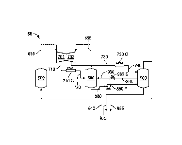
preferably a mid-boiling
refrigerant liquid stream. A high pressure MR recycle liquid stream 980
branches off of stream 975
and is provided to an expansion device 980E so that a high pressure MR recycle
mixed phase stream
990 is provided to interstage drum 800. This keeps the interstage drum 800
from running dry during
warm ambient temperatures (i.e. such as on a hot day). As described previously
(with respect to Fig.
23
Date Recue/Date Received 2023-08-15
3) and below, the recycle stream 980 could instead run directly from the high
pressure separation
device 900 to the expansion device 980E.
[0095] In contrast to the MR compressor system embodiments described above,
the interstage drum
800 of MR compressor system 60 includes a liquid outlet for providing a low
pressure MR liquid
stream 875 that has a high boiling temperature. The low pressure MR liquid
stream 875 is received
by a low pressure liquid cooling passage 187 of the heat exchanger 100 and is
further handled as
described below.
[0096] An alternative embodiment of the MR compressor system is indicated in
general at 62 of Fig.
14, and also includes an interstage drum 800 having a liquid outlet that
provides a low pressure MR
liquid stream 875.
[0097] In another alternative embodiment of the MR compressor system,
indicated in general at 64
in Fig. 15, a mixed phase primary MR stream 610 is returned from the heat
exchanger of Fig. 13 to
the suction separation device 600. The suction separation device 600 has a
liquid outlet through
which a suction drum MR liquid stream 675 exits the drum. The stream 675
travels to a suction
drum pump 675P, which produces suction drum MR stream 680, which travels to
interstage drum
800. Optional branch suction drum MR streams 681 and 682 may flow to the
compressed suction
drum MR vapor stream 710 and/or the cooled compressed suction drum MR stream
720.
[0098] Otherwise, the MR compressor system 64 of Fig. 15 is the same, and
functions the same, as
MR compressor system 60 of Fig. 13.
[0099] The heat exchange system 80 of Figs. 13 and 16 may be used with each of
the MR
compressor systems 60, 62 and 64 of Figs. 13, 14 and 15 (and alternative MR
compressor system
embodiments). The heat exchange system 80 and will now be discussed in detail
with reference to
Fig. 16.
[00100] As
illustrated in Fig. 16, and noted previously, the multi-stream heat exchanger
100
receives a feed fluid stream, such as a high pressure natural gas feed stream
5, that is cooled and/or
24
Date Recue/Date Received 2023-08-15
liquefied in feed stream cooling passage 103 via removal of heat via heat
exchange with
refrigeration streams in the heat exchanger. As a result, a stream of product
fluid 20 such as liquid
natural gas, is produced.
[00101] As in the case of the heat exchange system 70 of Fig. 7, the feed
stream cooling
passage 103 of heat exchange system 80 includes a pre-treatment feed stream
cooling passage 105,
having an inlet at the warm end of heat exchanger 100, and a treated feed
stream cooling passage
120 having a product outlet at the cold end through which product 20 exits.
The pre-treatment feed
stream cooling passage 105 has an outlet that joins feed fluid outlet 10 while
treated feed stream
cooling passage 120 has an inlet in communication with feed fluid inlet 15.
Feed fluid outlet and
inlet 10 and 15 are provided for external feed treatment (125 in Figs. 1 and
3), such as natural gas
liquids recovery, freezing component removal or nitrogen rejection, or the
like.
[00102] In an alternative embodiment of the heat exchange system, indicated
in general at 82
in Fig. 17, the feed stream cooling passage 103 passes between the warm and
cold ends of the heat
exchanger 100 without interruption. Such an embodiment may be used when
external feed treatment
systems are not heat integrated with the heat exchanger 100.
[00103] As in the case of the heat exchange system 70 of Fig. 7, the heat
exchanger 100
includes a refrigeration passage, indicated in general at 170 in Fig. 16, that
includes a cold
temperature refrigeration passage 140 having an inlet that receives, at the
cold end of the heat
exchanger, a cold temperature MR vapor stream 455 and a cold temperature MR
liquid stream 475.
The refrigeration passage 170 also includes a primary refrigeration passage
160 having a refrigerant
return stream outlet at the warm end of the heat exchanger, through which the
refrigerant return
stream 610 exits the heat exchanger 100, and a middle temperature refrigerant
inlet 150 adapted to
receive a middle temperature MR vapor stream 355 and a middle temperature MR
liquid stream 375
via corresponding passages. As a result, cold temperature MR vapor and liquid
streams (455 and
Date Recue/Date Received 2023-08-15
475) and middle temperature MR vapor and liquid streams (355 and 375) combine
within the heat
exchanger at the middle temperature refrigerant inlet 150.
[00104] The combination of the middle temperature refrigerant streams and
the cold
temperature refrigerant stream forms a middle temperature zone or region in
the heat exchanger
generally from the point at which they combine and downstream from there in
the direction of the
refrigerant flow toward the primary refrigeration passage outlet.
[00105] A primary MR stream 610 exits the primary refrigeration passage 160
of the heat
exchanger 100, travels to the MR compressor system of any of Figs. 13-15 and
is in the vapor phase
or mixed phase. As an example only, in the embodiments of Figs. 13 and 14, the
primary MR
stream 610 may be vapor. As the ambient temperature gets colder than design,
the primary MR
stream 610 will be mixed phase (vapor and liquid), and liquid will accumulate
in the suction drum
600 (of Figs. 13-15). After the process becomes steady state at the lower
temperature, the primary
MR stream is again all vapor at dew point. When the day waims up, the liquid
in the suction drum
600 will vaporize, and the primary MR stream will be all vapor. As a result,
the mixed phase
primary MR stream only occurs in transient conditions when the ambient
temperature is getting
colder than design. Alternatively, the system could be designed for a mixed
phase primary MR
stream 610.
[00106] The heat exchanger 100 also includes a high pressure vapor cooling
passage 195
adapted to receive a high pressure MR vapor stream 955 from any of the MR
compressor systems of
Figs. 13-15 at the warm end and to cool the high pressure MR vapor stream to
form a mixed phase
cold separator MR feed stream 210. Passage 195 includes an outlet in
communication with a cold
vapor separator 200, which separates the cold separator feed stream 210 into a
cold separator MR
vapor stream 255 and a cold separator MR liquid stream 275.
[00107] The heat exchanger 100 also includes a cold separator vapor cooling
passage 127
having an inlet in communication with the vapor outlet of the cold vapor
separator 200 so as to
26
Date Recue/Date Received 2023-08-15
receive the cold separator MR vapor stream 255. The cold separator MR vapor
stream is cooled in
passage 127 to form condensed cold temperature MR stream 410, and then flashed
with expansion
device 410E to form expanded cold temperature MR stream 420 which is directed
to cold
temperature standpipe 400. Expansion device 410E (and as in the case with all
"expansion devices"
disclosed herein) may be, as non-limiting examples, a Joule Thompson valve, a
turbine or an orifice.
[00108] Cold temperature standpipe 400 separates the mixed-phase stream 420
into a cold
temperature MR vapor stream 455 and a cold temperature MR liquid stream 475
which enter the
inlet of the cold temperature refrigerant passage 140.
[00109] The cold separator MR liquid stream 275 is cooled in cold separator
liquid cooling
passage 125 to form subcooled cold separator MR liquid stream 310.
[00110] A high pressure liquid cooling passage 197 receives high pressure
MR liquid stream
975 from any of the MR compressor systems of Fig. 13-15. The high pressure
liquid 975 is
preferably a mid-boiling refrigerant liquid stream. The high pressure liquid
stream enters the warm
end and is cooled to form a subcooled high pressure MR liquid stream 330. Both
refrigerant liquid
streams 310 and 330 are independently flashed via expansion devices 310E and
330E to form
expanded cold separator MR stream 320 and expanded high pressure MR stream
340. The expanded
cold separator MR stream 320 is combined with the expanded high pressure MR
stream 340 in mid-
temperature standpipe 300 to form middle temperature MR vapor stream 355 and
middle
temperature MR liquid stream 375. In alternative embodiments, the two streams
310 and 330 may
be mixed and then flashed.
[00111] The middle temperature MR streams 355 and 375 are directed to the
middle
temperature refrigerant inlet 150 of the refrigeration passage where they are
mixed with the
combined cold temperature MR vapor stream 455 and a cold temperature MR liquid
stream 475 and
provide refrigeration in the primary refrigeration passage 160. The
refrigerant exits the primary
27
Date Recue/Date Received 2023-08-15
refrigeration passage 160 as a vapor phase or mixed phase primary MR stream or
refrigerant return
stream 610. The return stream 610 may optionally be a superheated vapor
refrigerant return stream.
[00112] The heat exchanger 100 also includes a low pressure liquid cooling
passage 187 that,
as noted above, receives a low pressure MR liquid stream 875, that preferably
is high-boiling
refrigerant, from the liquid outlet of the interstage separation device or
drum 800 of any of the MR
compressor systems of Figs. 13-15. The high-boiling MR liquid stream 875 is
cooled in low
pressure liquid cooling passage 187 to form a subcooled low pressure MR
stream, which exits the
heat exchanger as stream 510. The subcooled low pressure MR liquid stream 510
is then flashed or
has its pressure reduced at expansion device 510E to form the expanded low
pressure MR stream
520. As examples only, stream 510 may have a pressure of 200 psig and a
temperature of -130 F,
while stream 520 may have a pressure of 50 psig and a temperature of -130 F.
Stream 520 is
directed to the mid-temperature standpipe 300, as illustrated in Fig. 16,
where it is combined with
expanded cold separator MR stream 320 and expanded high pressure MR stream
340. As a result,
high-boiling refrigerant is provided to the middle temperature refrigerant
inlet 150, and thus to the
primary refrigeration passage 160.
[00113] An alternative embodiment of the heat exchange system is indicated
in general at 84
in Fig. 18 and provides an alternative embodiment of the cold temperature MR
expansion loop.
More specifically, in this embodiment, the cold temperature standpipe 400 of
Figs. 13, 16 and 17 is
eliminated. As a result, the condensed cold temperature MR stream 410 from the
cold separator
vapor cooling passage 127 exits the cold end of the heat exchanger and is
flashed with expansion
device 410E to form cold temperature MR stream 465. Mixed phase stream 465
then enters the inlet
of the cold temperature refrigerant passage 140. The remainder of the heat
exchange system 84 is
the same, and operates in the same manner, as heat exchanger system 80 of Fig.
16. The feed stream
treatment outlet and inlet 10 and 15 (leading to and from a treatment system)
may be omitted, in the
manner shown for heat exchange system 82 of Fig. 17.
28
Date Recue/Date Received 2023-08-15
[00114] In another alternative embodiment of the heat exchange system,
indicated in general
at 86 in Fig. 19, the mid-temperature standpipe 300 of Figs. 16-18 has been
omitted. As a result, as
illustrated in Figs. 19 and 20, both refrigerant liquid streams 310 and 330
are independently flashed
via expansion devices 310E and 330E to form expanded cold separator MR stream
320 and
expanded high pressure MR stream 340. These two streams are combined with
expanded low
pressure MR stream 520 to form middle temperature MR stream 365 that flows
through middle
temperature refrigeration passage 136. Middle temperature MR stream 365 is
directed via passage
136 to the middle temperature refrigerant inlet 150 of the refrigeration
passage where it is mixed
with the cold temperature MR stream 465 to provide refrigeration in the
primary refrigeration
passage 160. The remainder of the heat exchange system 86 is the same, and
operates in the same
manner, as heat exchanger system 84 of Fig. 18. The feed stream treatment
outlet and inlet 10 and
15 (leading to and from a treatment system) may be omitted, in the manner
shown for heat exchange
system 82 of Fig. 17.
[00115] As illustrated in Fig. 21, the expansion devices 310E and 330E may
be omitted from
the passages of the subcooled cold separator MR stream 310 and subcooled high
pressure MR
stream 330. In this embodiment, an expansion device 315E is placed downstream
of the junction of
streams 310 and 330, but upstream of the junction with stream 520. As a
result, the stream 335
consisting of combined streams of 310 and 330 is flashed and then mixed with
stream 520 so that
middle temperature MR stream 365, which is mixed phase, is provided to the
middle temperature
refrigerant inlet 150 via passage 136.
[00116] In alternative embodiments, the expansion device 510E of Figs. 20
and 21 may be
omitted so that subcooled low pressure MR stream 510 is provided (instead of
stream 520) to mix
with stream 335 after expansion via expansion device 315E to form stream 365.
[00117] In another alternative embodiment illustrated in Fig. 22, stream
335 and stream 510
may be directed to a combined mixing and expansion device 136E. The device
136E, as an example
29
Date Recue/Date Received 2023-08-15
only, could have multiple inlets and separate liquid and vapor outlets. As
another example, two
liquid expanders in series, with the stream 510 fed in between, could be used.
[00118] In each of the above embodiments, one or more of an external
treatment, pre-
treatment, post-treatment, integrated treatment, or combination thereof may
independently be in
communication with the feed stream cooling passage and adapted to treat the
feed stream, product
stream, or both.
[00119] As an example, and noted previously with reference to Figs. 7 and
16, the feed stream
cooling passage 103 of the heat exchanger 100 includes a pre-treatment feed
stream cooling passage
105, having an inlet at the warm end of heat exchanger 100, and a treated feed
stream cooling
passage 120 having a product outlet at the cold end through which product 20
exits. The pre-
treatment feed stream cooling passage 105 has an outlet that joins feed fluid
outlet 10 while treated
feed stream cooling passage 120 has an inlet in communication with feed fluid
inlet 15. Feed fluid
outlet and inlet 10 and 15 are provided for external feed treatment (125 in
Figs. 1 and 3), such as
natural gas liquids recovery, freezing component removal or nitrogen
rejection, or the like.
[00120] An example of a system for external feed treatment, as used with MR
compressor
system 50 and heat exchange system 70, is indicated in general at 125 in Fig.
23. As illustrated in
Fig. 23, the feed fluid outlet 10 directs mixed-phased feed fluid to a heavies
knock out drum 12 (or
other separation device). The drum 12 includes a vapor outlet which is in
communication with feed
stream communication inlet 15 so that vapor from the separation device 12
travels to the treated
feed stream cooling passage 120 of the heat exchanger. The separation device
12 also includes a
liquid outlet through which a liquid stream 14 flows to heat exchanger 16,
where it is heated by heat
exchange with a refrigerant stream 18 provided by a branch off of the high
pressure MR liquid
stream 975 of the MR compressor system 50. The resulting heated liquid 19
flows to a condensate
stripping column 21 for further processing.
Date Recue/Date Received 2023-08-15
[00121] The external feed treatment 125 may also be combined with any of
the MR
compressor system and heat exchange system embodiments described above,
including MR
compressor system 52 and heat exchange system 70, as illustrated in Fig. 24,
and MR compressor
system 60 and heat exchange system 80, as illustrated in Fig. 25.
[00122] As illustrated at 22 in Figs. 23-25, the feed gas may be subjected
to pre-treatment via
a pre-treatment system 22 prior to entering the heat exchanger 100 as stream
5.
[00123] Each of the external treatment, pre-treatment, or post-treatment,
may independently
include one or more of removing one or more of sulfur, water, CO2, natural gas
liquid (NGL),
freezing component, ethane, olefin, C6 hydrocarbon, C6+ hydrocarbon, N2 , or
combination thereof,
from the feed stream.
[00124] Furthermore, one or more pre-treatment may independently include
one or more of
desulfurizing, dewatering, removing CO2, removing one or more natural gas
liquids (NGL), or a
combination thereof in communication with the feed stream cooling passage and
adapted to treat the
feed stream, product stream, or both.
[00125] In addition, one or more external treatment may independently
include one or more of
removing one or more natural gas liquids (NGL), removing one or more freezing
components,
removing ethane, removing one or more olefins, removing one or more C6
hydrocarbons, removing
one or more C6+ hydrocarbons, in communication with the feed stream cooling
passage and adapted
to treat the feed stream, product stream, or both.
[00126] Each of the above embodiments may also be provided with one or more
post-
treatments which may include removing N2 from the product and be in
communication with the feed
stream cooling passage and adapted to treat the feed stream, product stream,
or both.
[00127] While the preferred embodiments of the invention have been shown
and described, it
will be apparent to those skilled in the art that changes and modifications
may be made therein
31
Date Recue/Date Received 2023-08-15
without departing from the spirit of the invention, the scope of which is
defined by the appended
claims.
32
Date Recue/Date Received 2023-08-15