Note : Les descriptions sont présentées dans la langue officielle dans laquelle elles ont été soumises.
FUEL NOZZLE
TECHNICAL FIELD
[0001] The application relates generally to turbine engines and, more
particularly, to fuel
nozzles for turbine engines.
BACKGROUND OF THE ART
[0002] In a turbine engine, the areas surrounding the combustor have
elevated temperatures
because of the heat generated by the combustor as fuel is combusted therein.
Transfer of such
thermal energy may influence the function of components surrounding the
combustor, such as
fuel nozzles. For example, the structures defining passages via which fuel
flows inside fuel
nozzles may require particular thermal management consideration.
SUM MARY
[0003] According to an aspect of the present technology, there is provided
a fuel nozzle for a
turbine engine, comprising: a flange defining at least one flange passage; a
tip spaced from the
flange, the tip defining at least one tip passage; a stem having a first stem
end fixedly joined to
the flange and a second stem end fixedly joined to the tip, the stem having a
peripheral wall
extending lengthwise between the first stem end and the second stem end and
peripherally
around a stem chamber, the tip sealing the stem chamber at the second stem
end; and at least
one fuel line extending at least partially inside the stem chamber and having
a first line end fluidly
connected to the at least one flange passage and a second line end fluidly
connected to the at
least one tip passage.
[0004] According to another aspect of the present technology, there is
provided a turbine
engine comprising: a case surrounding an air plenum; a combustor surrounded by
the air plenum,
the combustor defining a combustion chamber; and a fuel nozzle for injecting a
fuel-air mixture
into the combustion chamber, the fuel nozzle comprising: a flange attached to
the case, the flange
defining at least one flange passage; a tip projecting into the combustion
chamber, the tip defining
at least one tip passage; a hollow stem body structurally connecting the tip
to the flange, the
hollow stem body having a peripheral wall extending lengthwise from a first
stem end to a second
stem end, the peripheral wall having an inner surface circumscribing a stem
chamber, the flange
and the tip sealing the stem chamber respectively at the first stem end and at
the second stem
1
Date Recue/Date Received 2023-08-29
end; and at least one fuel line extending through the stem chamber and fluidly
connecting the at
least one flange passage to the at least one tip passage.
DESCRIPTION OF THE DRAVVINGS
[0005] Reference is now made to the accompanying figures in which:
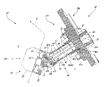
[0006] Fig. 1 is a schematic cross sectional view of a turbine engine; and
[0007] Fig. 2 is a cross-sectional view of a fuel nozzle of the turbine
engine of Fig. 1 taken
along the line 2-2 of Fig. 1.
DETAILED DESCRIPTION
[0008] Fig. 1 illustrates a gas turbine engine 10 of a type preferably
provided for use in
subsonic flight, generally comprising in serial flow communication a fan 12
through which ambient
air is propelled, a compressor section 14 for pressurizing the air, a
combustor 16 in which the
compressed air is mixed with fuel and ignited for generating an annular stream
of hot combustion
gases, and a turbine section 18 for extracting energy from the combustion
gases.
[0009] Referring to Figs. 1 and 2, the gas turbine engine 10 has fuel
nozzles 20 or injectors
mounted between an annular case 11 of the gas turbine engine 10 and the
combustor 16. The
case 11 surrounds a cavity E forming an air plenum, hereinafter "engine cavity
E", around the
combustor 16. The combustor 16 defines a combustion chamber C circumscribed by
radially inner
and radially outer combustor liners of the combustor 16 inside the engine
cavity E. Fig. 2 shows
an embodiment of one of the fuel nozzles 20. The illustrated nozzle 20
generally comprises a
number of external parts secured together, namely, a flange 30 which is
securable to the case
11, a stem 40 adapted to be disposed inside the engine cavity E and extending
from the flange
30, and a tip 50 inside the engine cavity E located at the end of the stem 40.
The flange 30 is
typically bolted to an exterior of the case 11. The stem 40 is configured to
structurally support the
tip 50 on the flange 30. A portion of the nozzle 20, which may include a
portion of the flange 30
and/or a portion of the stem 40, extends from outside the case 11 to inside
thereof via an opening
defined in the case 11. The tip 50 of the nozzle 20 is positioned so as to
extend through a
corresponding opening defined in a dome wall portion of the combustor 16, and
thus extends from
outside the combustion chamber C to inside the combustion chamber C. The tip
50 may be
monolithic or, as will be described further below, may comprise a plurality of
components 50', 50"
2
Date Recue/Date Received 2023-08-29
suitably assembled. In some embodiments, only one of such components 50', 50"
extends
through the opening of the combustor 16.
[0010] A first side 30a of the flange 30 generally faces away from the
combustor 16, whereas
a second side 30b of the flange 30 generally faces the stem 40 and the
combustor 16. A first side
40a of the stem 40 generally faces the flange 30, whereas a second side 40b of
the stem 40
generally faces the tip 50. A first side 50a of the tip 50 generally faces the
stem 40, whereas a
second side 50b of the tip 50 generally faces the combustor 16.
[0011] In operation, fuel is supplied to at least one fuel passage 32, 32'
of the flange 30 (or
flange passage 32, 32') of the illustrated nozzle 20, in this case from a
manifold (not shown) of
the engine 10 in fluid communication with a plurality of the fuel nozzles 20
of the engine 10. The
at least one fuel passage 32, 32' is defined by the flange 30 so as to
suitably condition the flow of
fuel downstream of the manifold. The fuel exits the fuel nozzle 20 at the tip
50 via at least one fuel
passage 52, 52' thereof (or tip passage 52, 52'), from which it is injected
into the combustor 16
and ignited to generate heat. The at least one fuel passage 52, 52' is defined
by the tip 50 as to
suitably condition the flow of fuel as it flows therein and/or exits
therefrom, for example to
incorporate air with the fuel so as to generate a spray.
[0012] The fuel nozzle 20 is configured to provide suitable fluid
connection(s) between the
fuel passage(s) 32, 32' of the flange 30 and the fuel passage(s) 52, 52' of
the tip 50. The fuel
nozzle 20 comprises at least one fuel line 60, 60' extending lengthwise, at
least partially, inside
the stem 40. Each one of the at least one fuel line 60, 60' has two opposite
ends, namely a first
end 60a, 60'a in fluid communication with a corresponding one of the at least
one fuel passages
32, 32' of the flange 30, and a second end 60b, 60'b in fluid communication
with a corresponding
one of the fuel passages 52, 52' of the tip 50. Depending on the embodiment,
the first end(s) 60a,
60'a and/or the second end(s) 60b, 60'b may extend outside the stem 40. The
fuel nozzle 20 may
be referred to as a "simplex" nozzle if it includes a sole fuel line 60, or as
a "duplex" nozzle if it
includes a pair of fuel lines 60, 60'. Fuel nozzles 20 having more than two
fuel lines, and a
corresponding number of fuel passages 32, 52, are contemplated.
[0013] The flange 30 can define one or more flange cavities 34, 36, for
example one such
cavity 34 located on the second side 30b of the flange 30 for receiving the
stem 40, and at least
one other such cavity 36 located on the first side 30a of the flange 30 in
fluid communication with
the at least one fuel passage 32, 32'.
3
Date Recue/Date Received 2023-08-29
[0014] The tip 50 can define one or more tip cavities 54, 56, 56', for
example one such cavity
54 located on the first side 50a of the tip 50 for receiving the stem 40, and
at least one other such
cavity 56, 56' located on the second side 50b of the tip 50 in fluid
communication with the at least
one fuel passage 52, 52'.
[0015] Still referring to Fig. 2, the stem 40 has a hollow stem body 42
(hereinafter "body") that
in this case is monolithic, and extends peripherally so as to circumscribe a
stem chamber 44
inside which the at least one fuel line 60, 60' extends, while providing
structure to the stem 40.
The at least one fuel line 60, 60' is spaced from the inner wall of the hollow
stem body 42 by an
annular insulating gap. Hence, in addition to supporting the tip 50, the stem
40 provides thermal
insulation to the at least one fuel line 60, 60'. Stated otherwise, the stem
40 serves a dual function
as it is both a support for the tip 50 and a heat shield for the at least one
fuel line 60, 60'. As such,
surrounding the stem 40 with a dedicated heat shield is not necessary in most
embodiments. The
body 42 is elongated, and extends lengthwise from a first end 42a of the stem
40, also referred
to as a proximal end 42a (i.e., the end that is the closest to the flange 30)
to a second end 42b
(i.e., the end that is the furthest from the flange 30), also referred to as a
distal end 42b. The stem
body 42 extends proximate to the flange 30 along a first stem axis, such that
it is matingly
connected to the flange 30 along the first stem axis. In this case, the first
stem end 42a is matingly
received by the flange cavity 34 defined on the second side 30b of the flange
30. The flange 30
may be said to seal the stem chamber 44 from the engine cavity E. The stem
body 42 extends
proximate to the tip 50 along a second stem axis, such that it is matingly
connected to the tip 50
along the second stem axis. In this case, the second stem end 42b is matingly
received by the tip
cavity 54 defined on the first side 50a of the tip 50. The tip 50 may be said
to seal the stem
chamber 44 from the combustion chamber C and from the engine cavity E.
Depending on the
embodiment, the stem body 42 may be said to follow a certain path as it
extends lengthwise. In
the present embodiment, the first stem axis and the second stem axis are
collinear, and thus
correspond to a same axis A. Also, in this embodiment, the stem body 42 fully
extends along the
axis A, and thus follows a linear path. In other embodiments, at least a
portion of the stem body
42 may follow a non linear path. In some such embodiments, the first stem axis
and the second
stem axis may be at an angle relative to one another.
[0016] As mentioned hereinabove, the stem body 42 is hollow, and may thus
be said to
include a peripheral wall having an outer surface 42c (i.e., a surface exposed
at least in part to
the engine cavity E) and an inner surface 42d (i.e., a surface circumscribing
the stem chamber
44). The stem body 42 may be cylindrical in shape, and thus may extend axially
and
4
Date Recue/Date Received 2023-08-29
circumferentially relative to the axis A, with the outer surface 42c and the
inner surface 42d being
spaced by a thickness T relative to the axis A, i.e., in this case a radial
thickness, that is the same
at the first stem end 42a, at the second stem end 42b, and at either axial
position therebetween.
Stated otherwise, the stem body 42 may have an outer diameter and an inner
diameter (shown
at D) that are constant throughout its length. Other configurations are
contemplated for the
peripheral wall.
[0017] The stem 40 and the at least one fuel line 60, 60' are sized and
arranged relative to
one another so as to provide suitable insulation to the at least one fuel line
60, 60' from the high
temperatures in effect in the vicinity of the fuel nozzle 20 as the engine 10
operates. For instance,
the temperature inside the engine cavity E around the combustor can attain
1000 F, or
approximately 593.3 C, whereas it may be desirable to maintain the stem
chamber 44 at a
temperature of about 600 F, or approximately 315.5 C, to minimize adverse
heating of the fuel as
it flows inside the at least one fuel line 60, 60'. For example, in order to
provide a suitable air gap
around the at least one fuel line 60, 60', the inner diameter D of the of the
peripheral wall of the
stem body 42 may be of between 7 and 15 times an outer diameter d of the at
least one fuel line
60, 60'. In some embodiments, the inner diameter D may be of between about 0.4
inch and 0.6
inch, for example 0.5 inch, i.e., between about 10.2 mm and 15.2 mm, for
example 12.7 mm. In
some such embodiments, the outer diameter d may be of between about 0.030 inch
and 0.090
inch, for example 0.060 inch, i.e., between about 0.76 mm and 2.30 mm, for
example 1.52 mm.
[0018] Still referring to Fig. 2, in order to hinder the transfer of heat
toward the fuel flowing
inside the at least one fuel line 60, 60', a portion of the volume
circumscribed by the outer surface
42c of the stem body 42 that is occupied by air (i.e., unoccupied by either of
the stem body 42 nor
the at least one fuel line 60, 60') may be maximised while maintaining the
requisite structural
integrity of the stem 40 as it holds the tip 50 relative to the flange 30. To
this end, the thickness T
of the peripheral wall of the stem body 42 may be much smaller than the inner
diameter D. For
example, the thickness T may be of between about 0.035 inch and 0.060 inch,
for example 0.050
inch, i.e., between about 0.89 mm and about 1.52 mm, for example 1.20 mm. In
embodiments,
the thickness T is at least at a location that is spaced away from the flange
30 and from the tip
50. The peripheral wall may have multiple thicknesses at respective lengthwise
locations. A
thickness of the at least one fuel line 60, 60' may be of between about 0.010
inch and 0.025 inch,
for example 0.015 inch, i.e., between about 0.254 mm and 0.635 mm, for example
0.38 mm. An
inner diameter of the at least one fuel line 60, 60' may be of between about
0.10 inch and 0.25
inch, i.e., between about 2.5 mm and 6.4 mm.
Date Recue/Date Received 2023-08-29
[0019] In some embodiments, the stem 40 may have an opening 46 defined in
the peripheral
wall at a location where the outer surface 42c is exposed to the engine cavity
E, with the opening
46 extending through the peripheral wall from the inner surface 42d to the
outer surface 42c. The
opening 46 is thus in fluid communication between the stem chamber 44 and the
engine cavity E,
and more specifically a portion of the engine cavity E that is outside the
combustor 16. By way of
the opening 46, the pressure inside the stem chamber 44 may tend to
equilibrate with that of the
engine cavity E. The opening 46 is sized so as to be small relative to the
stem chamber 44 so as
to prevent ingress of hot air into the stem chamber 44. For example, the
opening 46 may have a
cross-sectional area that is of less than about 0.15 % of an area of the outer
surface 42c that is
exposed to the engine cavity E. In embodiments, the opening 46 has a cross-
sectional area that
is no greater than about 0.0009 square inches, i.e., no greater than about 3
mm2. In embodiments,
the opening 46 is cylindrical in shape. In some such embodiments, the opening
46 may have a
diameter of between about 0.015 inch and 0.025 inch, i.e., between about 0.38
mm and 0.63 mm.
Also, the opening 46 may be located closer to the flange 30 than to the tip
50, such that it is
spaced away from the heat source (i.e., the combustor 16) and thus less
susceptible to let heat
enter the stem chamber 44. In embodiments, the opening 46 is a sole opening
defined in the
peripheral wall. In embodiments, more than one opening 46 is provided in the
peripheral wall.
[0020] Components of the fuel nozzle 20 interfacing one another may be
fixedly joined, i.e.,
permanently joined or in a manner not intended to be disjoined, by various
suitable means. For
example, the first stem end 42a and the second stem end 42b may be
respectively fixedly joined
to the flange 30 and to the tip 50 by brazing, welding or soldering. Likewise,
the first line end(s)
60a, 60'a and the second line end(s) 60b, 60'b may be respectively fixedly
joined to the flange 30
and to the tip 50 by brazing, welding or soldering. Advantageously, the fuel
nozzle 20 may be
arranged such that brazing can be used to fixedly join multiple components of
the fuel nozzle 20
in one heating operation or, stated otherwise, so that multiple joints of the
fuel nozzle 20 may be
brazed at once. It should be noted that the opening 46 may serve as a vent
during a heat treatment
cycle, for example a brazing cycle, so that pressures inside and outside the
stem chamber 44
may equilibrate, and/or for gasses generated or used during the heat treatment
cycle to evacuate
from the stem chamber 44. Fitment of any two components of the fuel nozzle 20
may refer to the
secure, yet non permanent assembly of such two components, in some cases with
a brazing
media (e.g., paste, powder, or preform material) disposed at the interface
therebetween. For
example, the first stem end 42a may be fitted to a complementary shape of the
flange 30, for
example the flange cavity 34, whereas the first line end(s) 60a, 60'a may be
fitted to
6
Date Recue/Date Received 2023-08-29
complementary shape(s) of the flange 30, for example distal portion(s) of the
fuel passages 32,
32'. The second stem end 42b may be fitted to a complementary shape of the tip
50, for example
the tip cavity 54, whereas the second line end(s) 60b, 60'b may be fitted to
complementary
shape(s) of the tip 50, for example proximal portion(s) of the fuel passages
52, 52'. In the depicted
embodiment, the outer surface 42c of the stem body 42 interfaces a radially
inner surface of the
flange 30 at the first stem end 42a, and interfaces a radially inner surface
of the tip 50 at the
second stem end 42b. As such, the first and second stem ends 42a, 42b are
respectively recessed
in, or matingly received by, the flange 30 and the tip 50, such that end
portions of the stem
chamber 44 may be said to be located inside the flange 30 and inside the tip
50. Stated otherwise,
the stem chamber 44 may extend from inside the flange 30 to inside the tip 50
In other
embodiments, the inner surface 42d of the stem body 42 may interface a
radially outer surface of
the flange 30 and/or a radially outer surface of the tip 50. The fuel nozzle
20 may be arranged so
as to facilitate the simultaneous fitment of the stem 40 and of the at least
one fuel line 60, 60' to
the flange 30 and/or to the tip 50. For example, upon the flange 30 being
fitted onto the stem 40
and onto the at least one fuel line 60, 60', the first stem end 42a and the
first line end(s) 60a, 60'a
may extend parallel to one another, and/or the second stem end 42b and the
second line end(s)
60b, 60'b may extend parallel to one another. Upon the tip 50 being fitted
onto the stem 40 and
onto the at least one fuel line 60, 60', the second stem end 42b and the
second line end(s) 60b,
60'b may extend parallel to one another, and/or the first stem end 42a and the
first line end(s)
60a, 60'a may extend parallel to one another. The at least one fuel line 60,
60' may be cylindrical
in shape. In some such embodiments, the stem 40 and the at least one fuel line
60, 60' are all
cylindrical in shape, and extend parallel to one another upon the nozzle 20
being assembled.
[0021] The flange 30, the stem 40, the tip 50 and/or the at least one fuel
line 60, 60' are
constructed of material(s) that are suitable for the joining means employed to
assemble the nozzle
20. For example, in the case of brazing, such material(s) are metallic
materials having a melting
temperature that is higher than that of the brazing media. In some
embodiments, the material(s)
have a melting temperature that is of at least 2200 F (1204 C). The
material(s) of which the stem
40 and/or the at least one fuel line 60, 60' may have particularly desirable
properties in accordance
with the dual function of the stem 40, for example high rigidity and low
thermal conductivity.
[0022] At least in some embodiments, the stem 40 and/or the at least one
fuel line 60, 60' are
obtained from standardized structures requiring minimal machining steps before
being assembled
so as to form the nozzle 20. For instance, the stem 40 and/or the at least one
fuel line 60, 60' can
be made of tubing, in some cases having nominal dimensions that are readily
available off-the-
7
Date Recue/Date Received 2023-08-29
shelf. In some embodiments, a sole machining step to which the stem 40 and/or
the at least one
fuel line 60, 60' is/are submitted is lengthwise cutting. According to one
aspect, the stem body 42
can be provided in the form of an outer tube and the at least one fuel line
60, 60' can be provided
in the form of internal tube(s) inside the outer tube, thereby forming a
nested tube arrangement.
[0023]
The embodiments described in this document provide non-limiting examples of
possible implementations of the present technology. Upon review of the present
disclosure, a
person of ordinary skill in the art will recognize that changes may be made to
the embodiments
described herein without departing from the scope of the present technology.
Yet further
modifications could be implemented by a person of ordinary skill in the art in
view of the present
disclosure, which modifications would be within the scope of the present
technology.
8
Date Recue/Date Received 2023-08-29