Note : Les descriptions sont présentées dans la langue officielle dans laquelle elles ont été soumises.
General Correspondence (Patent)
Date: September 1, 2023 5:49:05 AM
3210974
Application Number #4667572
jr
40 pages
Title of invention
DRUG DELIVERY DEVICE
Applicant(s) or Inventor Name(s)
Applicant or Inventor Name
Sender
Family Name: Courage
First Name: Noel
Initial:
Name of Corporation or Firm: BERESKIN & PARR LLP
Address Line 1: Scotia Plaza
Address Line 2: 40 King Street West
Address Line 3: 40th Floor
City/Town: Toronto
Province/State: Ontario
Country: Canada
Postal/Zip Code: M5H 3Y2
Telephone Number: 4163647311
Fax Number: 416-361-1398
Email Address: cipomail@bereskinparr.com
Communicate by: Electronic Mail (Non secure)
Correspondence Instructions
Date Recue/Date Received 2023-09-01
We enclose herewith the application papers for a patent application entitled
DRUG
DELIVERY DEVICE, which is to be filed in the name of SENSILE MEDICAL AG
who hereby requests that a patent may be granted for the invention described
and
claimed in these application papers. We enclose a Statement of Entitlement
pursuant to
Section 54 of the Patent Rules. We also enclose an assignment from the
inventors to the
Applicant in respect of the above-noted application. Registration of the
assignment
under Section 124 of the Patent Rules is hereby requested.
Description of Fee (standard fee)
1. Application Fee (1 x $421.02): $421.02
2. Examination of an application (1 x $816.00): $816.00
3. Registration of a document - section 124 (1 x $100.00): $100.00
Total Fee Payment: $1,337.02
Payment method
Common Payment Component
Attachments
1. CIPO - Petition Ltr BP Ref. 16194-P72769CA00.PDF
Other
CIPO Ltr - New Filing
2. CIPO - Petition BP Ref. 16194-P72769CA00.PDF
Petition/Request of Entry into National Phase
Petition
3. CIPO - Abstract BP Ref. 16194-P72769CA00.PDF
Abstract
Abstract
4. CIPO - Description BP Ref. 16194-P72769CA00.PDF
Description
Description
5. CIPO - Claims BP Ref. 16194-P72769CA00.PDF
Claim
Claims
Date Recue/Date Received 2023-09-01
6. CIPO - Drawings BP Ref. 16194-P72769CA00.PDF
Drawing
Drawings
7. CIPO - Statement of Entitlement BP Ref. 16194-P72769CA00.PDF
Other
Statement of Entitlement
8. P2690EP00 - Confirmatory Assignment signed.PDF
Other
Assignment
Transmission Identifier: pgc_kbeaulac_20230901054905549_15870153
Date: September 1, 2023 5:49:05 AM
Commissioner of Patents
50 Victoria Street
Place du Portage
Phase I
Gatineau, Quebec
Canada
KlA 0C9
Application Number:
Title of invention: DRUG DELIVERY DEVICE
Applicant(s) or Inventor(s) Name(s): SENSILE MEDICAL AG
SENSILE MEDICAL AG
Reference Number: 16194-P72769CA00
Instructions: We enclose herewith the application papers for a patent
application
entitled DRUG DELIVERY DEVICE, which is to be filed in the name of SENSILE
MEDICAL AG who hereby requests that a patent may be granted for the invention
described and claimed in these application papers. We enclose a Statement of
Entitlement pursuant to Section 54 of the Patent Rules. We also enclose an
assignment
from the inventors to the Applicant in respect of the above-noted application.
Registration of the assignment under Section 124 of the Patent Rules is hereby
requested.
Attached are the following documents:
1. CIPO - Petition Ltr BP Ref. 16194-P72769CA00.PDF
CIPO Ltr - New Filing
Other
2. CIPO - Petition BP Ref. 16194-P72769CA00.PDF
Petition
Date Recue/Date Received 2023-09-01
Petition/Request of Entry into National Phase
3. CIPO - Abstract BP Ref. 16194-P72769CA00.PDF
Abstract
Abstract
4. CIPO - Description BP Ref. 16194-P72769CA00.PDF
Description
Description
5. CIPO - Claims BP Ref. 16194-P72769CA00.PDF
Claims
Claim
6. CIPO - Drawings BP Ref. 16194-P72769CA00.PDF
Drawings
Drawing
7. CIPO - Statement of Entitlement BP Ref. 16194-P72769CA00.PDF
Statement of Entitlement
Other
8. P2690EP00 - Confirmatory Assignment signed.PDF
Assignment
Other
Description of Fee (standard fee)
1. Application Fee (1 x $421.02): $421.02
2. Examination of an application (1 x $816.00): $816.00
3. Registration of a document - section 124 (1 x $100.00): $100.00
Total Fee Payment: $1,337.02
Courage, Noel
BERESKIN & PARR LLP
Scotia Plaza
40 King Street West
40th Floor
Toronto
Ontario
Canada
M5H 3Y2
Tel: 4163647311
Fax: 416-361-1398
Email:cipomail@bereskinparr.com
Transmission Identifier: pgc_kbeaulac_20230901054905549_15870153
Date Recue/Date Received 2023-09-01
Beresm
1
arr
Noel Courage B.Sc. (Biochem.), LL.B.
416.957.1655 ncourage@bereskinparr.com
September 1, 2023 Our Reference: 16194-P72769CA00
New Filing
The Commissioner of Patents
Canadian Intellectual Property Office
Place du Portage I
50 Victoria Street, Room C-114
Gatineau, Quebec K1A 0C9
Dear Commissioner:
Re: New Canadian Patent Application
DRUG DELIVERY DEVICE
Applicant: SENSILE MEDICAL AG
We enclose herewith the application papers for a patent application entitled
DRUG DELIVERY
DEVICE, which is to be filed in the name of SENSILE MEDICAL AG who hereby
requests that a
patent may be granted for the invention described and claimed in these
application papers.
We enclose a Statement of Entitlement pursuant to Section 54 of the Patent
Rules.
We also enclose an assignment from the inventors to the Applicant in respect
of the above-noted
application. Registration of the assignment under Section 124 of the Patent
Rules is hereby
requested.
Applicant requests that this application be made available to WIPO Digital
Access Service (DAS).
Applicant submits the below WIPO Digital Access Service (DAS) code
corresponding to the
priority application for this patent application:
Priority Country Priority Application No. Priority Filing Date Access Code
Europe 22195657.6 September 14, 2022 EB8F
Pursuant to Subsection 35(1) of the Patent Act, the Applicant respectfully
requests that this
application be examined.
Pursuant to Subsection 80(1) of the Patent Rules, the Applicant respectfully
submits that there
are no claims in excess of 20 included in the application and therefore no
excess claims fees are
required.
The government fee of $1,337.02 is to be charged to our firm's Visa account.
Date Regue/Date Received 2023-09-01
Application Fee $421.02
Basic Examination Fee $816.00
Assignment Registration Fee $100.00
TOTAL $1,337.02
The Applicant requests that this application be maintained in good standing,
and not
abandoned. The Applicant has no intention of permitting this application to
become
abandoned. If this application is abandoned now, for any reason, then
reinstatement is
requested as of the date of this letter and CIPO is authorized to charge
payment of the
reinstatement fee and all prescribed fees necessary to our Deposit account no.
600000016.
Should the fees submitted with this letter be insufficient to cover all the
fees for which
payment is explicitly or implicitly requested by this letter, including the
payment of any
maintenance fees, reinstatement fees, late fees, excess claims fees and/or
additional fees
for late payment that may be required, CI PO is authorized to charge the
amount of the
insufficiency to our Deposit account no. 600000016 at the standard rate.
Please file the application upon receipt.
We hereby request that correspondence for this application be sent by email to
cipomail@bereskinparr.com.
Respectfully submitted,
BERESKIN & PARR LLP/S.E.N.C.R.L., s.r.l.
Agent for the Applicant
84.1.014. +7)100v* 1-02,04,1rea ee'41.0,
Noel Courage
Ends.
(1) Petition
(2) Abstract
(3) Disclosure (16 pages)
(4) Claims (14 claims)
(5) Drawings (9 sheets)
(6) Statement of Entitlement pursuant to Section 54 of the Patent Rules
(7) Assignment document
Date Recue/Date Received 2023-09-01
Bereskil
&Parr
CANADA
File No.: 16194-P72769CA00
PETITION
1. Applicant and Title of Invention
The Applicant is SENSILE MEDICAL AG whose postal address is Solothurnerstrasse
235, OLTEN CH-4600, Switzerland.
The Applicant requests the grant of a patent for an invention entitled DRUG
DELIVERY
DEVICE, which is described and claimed in the accompanying specification.
2. Inventor Information
The name and address of each inventor of the subject-matter of the invention
for which
exclusive privilege or property is claimed is set out below:
(a) LAGORGETTE, Pascal
of Quai du Bas 37, Bienne 2502, Switzerland;
(b) BURL!, Fabian
of Staffelackerweg 5, StOsslingen 4655, Switzerland;
(c) MOLLER, Matthias
of MOhlering 25, Hagendorf CH-4614, Switzerland; and
(d) KOSTAL, Peer
of Im Hof 6, Rheinfelden D-79618, Germany.
3. Appointment of Patent Agent(s)
The Applicant appoints all of the patent agents at Bereskin & Parr
LLP/S.E.N.C.R.L.,
s.r.I., to represent them before the Patent Office in respect of the patent
application.
For purposes of correspondence, the postal address of the head office for
Bereskin &
Parr LLP/S.E.N.C.R.L., s.r.I., is Scotia Plaza, 40 King Street West, 40th
Floor, Toronto,
Ontario M5H 3Y2.
4. Request for Priority
The Applicant requests priority in respect of the application on the basis of
the following
previously filed application:
Country/Office of Filing Filing Date Application Access Code
European Patent September 14, 2022 22195657.6 EB8F
5. Preferred Figure
Date Recue/Date Received 2023-09-01
The Applicant requests that Figure Number 1, of the drawings accompany the
abstract
when it is open to public inspection under section 10 of the Patent Act or
published.
SIGNED at Toronto, Ontario, Canada, this 1st day of September, 2023
0841414... +?0,1e. Lce/Xaid 4%"*.*y.,
Noel Courage
BERESKIN & PARR LLP/S.E.N.C.R.L., s.r.l.
Agents for the Applicant
Date Recue/Date Received 2023-09-01
Beres i
. H
& him' arl
CANADA
STATEMENT PURSUANT TO
SECTION 54 OF THE PATENT RULES
Title: DRUG DELIVERY DEVICE
Applicant: SENSILE MEDICAL AG
B&P Ref.: 16194-P72769CA00
1. Z The Applicant is entitled to apply for the patent.
The names and addresses of the inventors are:
(a) LAGORGETTE, Pascal
of Quai du Bas 37, Bienne 2502, Switzerland;
(b) BURL!, Fabian
of Staffelackerweg 5, StOsslingen 4655, Switzerland;
(c) MOLLER, Matthias
of MOhlering 25, Hagendorf CH-4614, Switzerland; and
(d) KOSTAL, Peer
of Im Hof 6, Rheinfelden D-79618, Germany.
Date Recue/Date Received 2023-09-01
P2690EPOO
CONFIRMATORY ASSIGNMENT OF
INTELLECTUAL PROPERTY RIGHTS
We, the undersigned
Family name, Name presently residing at Employer
LAGORGETTE, Pascal Quai du Bas 37 Sensile Medical AG
2502 Bienne Solothurnerstrasse 235
Switzerland CH- 4600 Olten
Switzerland
BORLI, Fabian Staffelackerweg 5 Sensile Medical AG
4655 Stasslingen Solothurnerstrasse 235
Switzerland CH- 4600 Olten
Switzerland
MOLLER, Matthias Muhlering 25 Sensile Medical AG
4614 Hagen dorf Solothurnerstrasse 235
Switzerland CH- 4600 Olten
Switzerland
KOSTAL, Peer Im Hof 6 Sensile Medical AG
D-79618 Rheinfelden Solothurnerstrasse 235
Germany CH- 4600 Olten
Switzerland
declare that we have made together an invention regarding "DRUG DELIVERY
DEVICE"
described in the attached Annex A (EP patent application No. 22195657.6 filed
on 14
September 2022 (hereinafter the "Invention").
We believe that we are each an original joint inventor of a claimed invention
in the application.
We further hereby confirm that the invention has been conceived in the course
and within
the scope of our employment duties towards our Employer. Pursuant to Swiss
employment
law and our employment contracts with our Employer, we hereby confirm that, as
concerns
our respective contribution to the developpement of the invention, all shares
of rights to the
Invention have been automatically assigned to our Employer at the time the
invention was
made.
For the avoidance of doubt and to the extent that any rights may not have been
assigned, we
hereby assign and confirm assignment of the entire rights and interest in and
to said
Invention, including all rights to file patent applications regarding the
invention and the rights
to claim priority from those patent applications in any country in the world,
to our Employer
at the time the invention was made who accepts the Assignment without any
restrictions and
with all rights and obligations deriving therefrom, in consideration of the
sum of ten Swiss
Francs (CHF10.00) to each of us and other good and valuable consideration now
paid by
SENSILE MEDICAL AG ("The Employer"), the receipt and sufficiency of which we
hereby
acknowledge.
We agree to testify and execute any papers for the Employer, its successors,
assigns and legal
representatives, deemed essential by the Employer to the Employer's protection
and title in
and to the shares of rights to the invention hereby transferred. We also agree
that the
SENSILE MEDICAL AG solely executes registration of this assignment before the
Patent
Offices.
Family name, Name place, date signature
LAGORGETTE, Pascal /11 /202a
6/leh
Date Recue/Date Received 2023-09-01 1 /2
P2690EPOO
BURL', Fabian
OrecA ZeZZ
MOLLER, Matthias
0(61( io.
KOSTAL, Peer
Otibe ) 2 el, ,0.202
1(0,444A,
'SENSILE MEDICAL AG 1>th, A4?At5
N e: 7
/1,(ferbxlc_ 1crirQHEsitt
Position: CEO sef6leivAeckictIl
Swot immr
=
Date Recue/Date Received 2023-09-01 2/2
ABSTRACT
A drug delivery device (1), comprising a delivery unit (3) including a drug
container (6)
comprising a barrel portion (6a) and a plunger (12) slidably mounted within
the barrel portion
and sealing the drug (78) within the container at one end of the barrel
portion, and a drive unit
(4) comprising a pneumatic flow system (74) and a pneumatic pumping system
configured to
pump air via the pneumatic flow system (74) to a space behind the plunger to
generate a gas
pressure to advance the plunger in the container during drug delivery. The
drug delivery device
comprises a sealing adaptor (9) mounted on an end of the drug container facing
an outer side
of the plunger, the sealing adaptor (9) comprising a sealing plug (23)
inserted inside an end of
the barrel portion, the sealing plug (23) comprising an orifice (26)
configured for pluggable
sealing connection to a gas channel connector (40) of the pneumatic flow
system.
Date Recue/Date Received 2023-09-01
CLAIMS
1. A drug delivery device (1), comprising a delivery unit (3) including a
drug container (6)
comprising a barrel portion (6a) and a plunger (12) slidably mounted within
the barrel portion
and sealing the drug (78) within the container at one end of the barrel
portion, and a drive unit
(4) comprising a pneumatic flow system (74) and a pneumatic pumping system
configured to
pump air via the pneumatic flow system to a space behind the plunger to
generate a gas
pressure to advance the plunger in the container during drug delivery,
characterized in that
the drug delivery device comprises a sealing adaptor (9) mounted on an end of
the drug
container facing an outer side of the plunger, the sealing adaptor comprising
a sealing plug
(23) inserted inside an end of the barrel portion, the sealing plug comprising
an orifice (26)
configured for pluggable sealing connection to a gas channel connector (40) of
the pneumatic
flow system.
2. The drug delivery device according to the preceding claim wherein the
gas channel
connector (40) comprises a tubular end portion pluggably inserted in the
orifice (26) of the
sealing plug.
3. The drug delivery device according to any preceding claim wherein the
sealing plug
comprises an inner radial sealing ring (25) comprising a portion extending
axially from an end
wall (27) of the sealing plug, said orifice for sealing connection to the gas
channel connector
being formed within the inner radial sealing ring.
4. The drug delivery device according to the preceding claim wherein the
plunger (12)
comprises a back end (73) forming a cavity, said axial extension of the inner
radial sealing ring
being positioned at least partially in the cavity in an initial position prior
to drug delivery.
5. The drug delivery device according to any preceding claim wherein the
sealing plug
comprises an outer radial sealing ring (24) comprising a portion extending
axially from an end
wall (27) of the sealing plug, the outer radial sealing ring sealingly
engaging an inner surface
of the barrel portion of the drug container.
6. The drug delivery device according to any preceding claim wherein the
sealing adaptor
comprises a cap (19) inserted over an end of the barrel portion, the cap
comprising an end
wall engaging a back end of the sealing plug and one or more locking members
(20) engaging
a housing component of the delivery unit in which the drug container is
received.
Date Recue/Date Received 2023-09-01
7. The drug delivery device according to the preceding claim wherein the
housing
component of the delivery unit is a container casing (38) within which the
drug container is
inserted in the delivery unit (3), the locking member of the sealing adaptor
cap engaging the
complementary locking member on the container casing.
8. The drug delivery device according to the preceding claim wherein the
one or more
locking members on the cap comprises one or more elastic latches having a
locking shoulder
engaging a complementary locking shoulder on the outside of the container
casing.
9. The drug delivery device according to any of the three directly
preceding claims wherein
the cap of the sealing adaptor comprises a circular channel between an outer
ring wall (17a)
and an inner ring wall (17b), the outer ring wall engaging over an outer end
of the barrel portion
of the drug container and the inner radial wall forming a space with the wall
of the drug
container within which an outer radial sealing ring (24) of the sealing plug
is lodged.
10. The drug delivery device according to any preceding claim wherein the
pneumatic flow
system (74) comprises a channel housing component (41) within which a gas
channel (42) is
formed extending between the gas channel connector (40) and the outlet of the
pump engine
(28).
11. The drug delivery device according to the preceding claim wherein the
gas channel
housing component (41) is formed as a separated part assembled in the drive
unit (4) to the
pump engine.
12. The drug delivery device according to any preceding claim, wherein the
pneumatic
pumping system comprises a pump engine (28) including
- a stator (28a),
- a rotor (28b) rotatably and axially slidably mounted at least partially
in the stator, the
rotor comprising a first axial extension having a first diameter and the
second axial extension
having a second diameter greater than the first diameter,
- a first valve formed by a first valve seal mounted on the stator around
the first axial
extension, in conjunction with a first channel in the rotor that is configured
to allow fluidic
communication across the first valve seal when the first valve is in an open
position, and
- a second valve formed by a second valve seal mounted on the stator around
the
second axial extension, in conjunction with a second channel in a rotor that
is configured to
allow fluidic communication across the second valve seal when the second valve
is an open
position.
Date Recue/Date Received 2023-09-01
13. The drug delivery device according to any preceding claim, wherein
the drug container
is a drug cartridge and comprises a septum (6c) at one end.
14. The drug delivery device according to any preceding claim, wherein the
drive unit
comprises an electronic control system and a pressure sensor (80) fluidically
coupled to
pneumatic flow system for measuring a gas pressure behind the plunger, the
pressure sensor
connected to the electronic control system (47) of the drive unit configured
to measure a
pressure detected by the pressure sensor over time and to determine from the
pressure
measurement over time a position of the plunger over time, including a stop in
movement of
the plunger either due to occlusion in the drug delivery flow system or an end
of travel of the
plunger within the container corresponding to a container empty position.
Date Recue/Date Received 2023-09-01
DRUG DELIVERY DEVICE
TECHNICAL FIELD
This invention relates to a drug delivery device for subcutaneous
administration of a liquid
drug. The invention in particular relates to a drug delivery device in the
form of a patch device.
DESCRIPTION OF RELATED ART
Drug delivery devices in the form of a patch device for mounting on a
patient's skin for
subcutaneous delivery of liquid drug are known. It is known to provide drug
delivery devices in
the form of a patch device with a single use disposable component assembled to
a reusable
component containing drive and control electronics, or as a single disposable
component.
Some devices typically receive a cartridge or have an internal reservoir that
is filled by the
patient! healthcare professional. In this case, the drug is drawn from a vial
and transferred into
the internal reservoir using a syringe. Since cartridges are widespread and
their handling is so
much easier, it is advantageous to provide a device that can be employed with
standard
cartridges.
The liquid drug may for instance be a biological medical product or other
drugs that are
administered merely for single shot administration, within a rather short time
depending on the
intended use.
In order to satisfy safety and reliability requirements, many conventional
patch pump drug
delivery devices have complex pump mechanisms and are rather bulky. The
reliability, safety,
compactness and ease of use of drug delivery devices worn by a patient is
important, however
for single shot administration, there is a reduced need for complex motor
systems since one
does not need to ensure accurate intermittent bolus or basal administration
over a prolonged
period extending over days or weeks. For disposable components, the amount of
parts and
consequently cost of the disposable device is also an important consideration.
Conventional
patch pumps to be worn by a patient are typically too complex and costly for
single shot
administration applications.
SUMMARY OF THE INVENTION
In view of the foregoing, it is an object of the invention to provide a drug
delivery device, in
particular in the form of a patch device, with a disposable unit, or as an
entirely disposable
device, for single shot administration of a liquid drug that is safe,
reliable, and compact.
Date Recue/Date Received 2023-09-01
It is advantageous to provide a drug delivery device that may be used for
administration of
liquid drugs provided in a drug container with a plunger.
It is advantageous to provide a drug delivery device that is easy to use.
It is advantageous to provide a drug delivery device that is economical to
produce.
It is advantageous to provide a drug delivery device that has a long shelf
life
Objects of the invention have been achieved by providing the drug delivery
device according
to claiml . Dependent claims set forth various advantageous embodiments of the
invention.
Disclosed herein is a drug delivery device, comprising a delivery unit
including a drug container
comprising a barrel portion and a plunger slidably mounted within the barrel
portion and sealing
the drug within the container at one end of the barrel portion, and a drive
unit comprising a
pneumatic flow system and a pneumatic pumping system configured to pump air
via the
pneumatic flow system to a space behind the plunger to generate a gas pressure
to advance
the plunger in the container during drug delivery.
The drug delivery device comprises a sealing adaptor mounted on an end of the
drug container
facing an outer side of the plunger, the sealing adaptor comprising a sealing
plug inserted
inside an end of the barrel portion, the sealing plug comprising an orifice
configured for
pluggable sealing connection to a gas channel connector of the pneumatic flow
system.
In an advantageous embodiment, the gas channel connector comprises a tubular
end portion
pluggably inserted in the orifice of the sealing plug.
In an advantageous embodiment, the sealing plug comprises an inner radial
sealing ring
comprising a portion extending axially from an end wall of the sealing plug,
said orifice for
sealing connection to the gas channel connector being formed within the inner
radial sealing
ring.
In an advantageous embodiment, the plunger comprises a back end forming a
cavity, said
axial extension of the inner radial sealing ring being positioned at least
partially in the cavity in
an initial position prior to drug delivery.
In an advantageous embodiment, the sealing plug comprises an outer radial
sealing ring
comprising a portion extending axially from an end wall of the sealing plug,
the outer radial
sealing ring sealingly engaging an inner surface of the barrel portion of the
drug container.
Date Recue/Date Received 2023-09-01
In an advantageous embodiment, the sealing adaptor comprises a cap inserted
over an end
of the barrel portion, the cap comprising an end wall engaging a back end of
the sealing plug
and one or more locking members engaging a housing component of the delivery
unit in which
the drug container is received.
In an advantageous embodiment, the housing component of the delivery unit is a
container
casing within which the drug container is inserted in the delivery unit, the
locking member of
the sealing adaptor cap engaging the complementary locking member on the
container casing.
In an advantageous embodiment, the one or more locking members on the cap
comprises one
or more elastic latches having a locking shoulder engaging a complementary
locking shoulder
on the outside of the container casing.
In an advantageous embodiment, the cap of the sealing adaptor comprises a
circular channel
between an outer ring wall and an inner ring wall, the outer ring wall
engaging over an outer
end of the barrel portion of the drug container and the inner radial wall
forming a space with
the wall of the drug container within which an outer radial sealing ring of
the sealing plug is
lodged.
In an advantageous embodiment, the pneumatic flow system comprises a channel
housing
component within which a gas channel is formed extending between the gas
channel
connector and the outlet of the pump engine.
In an advantageous embodiment, the gas channel housing component is formed as
a
separated part assembled in the drive unit to the pump engine.
In an advantageous embodiment, the pneumatic pumping system comprises a pump
engine
including
a stator,
a rotor rotatably and axially slidably mounted at least partially in the
stator, the rotor comprising
a first axial extension having a first diameter and the second axial extension
having a second
diameter greater than the first diameter,
a first valve formed by a first valve seal mounted on the stator around the
first axial extension,
in conjunction with a first channel in the rotor that is configured to allow
fluidic communication
across the first valve seal when the first valve is in an open position, and
Date Recue/Date Received 2023-09-01
a second valve formed by a second valve seal mounted on the stator around the
second axial
extension, in conjunction with a second channel in a rotor that is configured
to allow fluidic
communication across the second valve seal when the second valve is an open
position.
In an advantageous embodiment, the drug container is a drug cartridge and
comprises a
septum at one end.
In an advantageous embodiment, the drive unit comprises an electronic control
system and a
pressure sensor fluidically coupled to pneumatic flow system for measuring a
gas pressure
behind the plunger, the pressure sensor connected to the electronic control
system of the drive
unit configured to measure a pressure detected by the pressure sensor over
time and to
determine from the pressure measurement over time a position of the plunger
over time,
including a stop in movement of the plunger either due to occlusion in the
drug delivery flow
system or an end of travel of the plunger within the container corresponding
to a container
empty position.
Further objects and advantageous features of the invention will be apparent
from the claims,
from the detailed description, and annexed drawings, in which:
BRIEF DESCRIPTION OF THE DRAWINGS
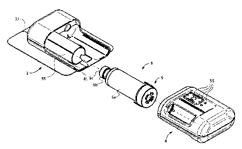
Figure 1 is a perspective view of a drug delivery device according to an
embodiment of the
invention, showing a disposable delivery unit, a drug container, and a
reusable unit in a
disassembled state;
Figure la is a perspective view of the drug container with sealing adaptor
mounted thereon of
the device of figure 1;
Figure 2a is a perspective view of a portion of the drug delivery device
according to an
embodiment of the invention, showing a drug container housing part, sealing
adaptor, and
pneumatic flow system;
Figure 2b is an exploded view of figure 2a;
Figure 2c is a cross-sectional view through a plane 2c-2c of figure 2a;
Figures 3a to 3d are cross-sectional views of a portion of the drug delivery
device showing a
drug container housing part, drug container, sealing adaptor, and pneumatic
flow system
according to an embodiment of the invention, figure 3a showing the device
prior to coupling of
the disposable and reusable parts, figure 3b showing the device coupled;
figure 3c showing
the device in use during drug delivery, and figure 3d showing the device after
drug delivery
with the reusable and disposable units separated;
Figure 4 is a view similar to figure 3a of another embodiment;
Date Recue/Date Received 2023-09-01
Figure 5a is a schematic illustration of a drug delivery device according to
an
embodiment of the invention illustrating a pneumatic drive and a pneumatic
plunger sensing
system;
Figure 5b is a schematic illustration of a plot of pressure as a function of
time of the
pneumatic plunger system according to an embodiment of the invention;
Figure 5c is a schematic illustration of a plot of flow rates of a drug over
time measured
by a pneumatic plunger sensing system according to an embodiment of the
invention;
Figure 5d is a corresponding plot of an air pumping pressure over time in the
pneumatic
flow system of the drug delivery device;
Figure 5e is a detail portion of the plot of air pumping pressure.
DETAILED DESCRIPTION OF EXEMPLARY EMBODIMENTS
Referring to the figures, a drug delivery device 1 according to embodiments of
the invention
comprise a housing 2, a delivery unit 3, and a control or drive unit 4, the
delivery unit 3 and the
control or drive unit 4 being assembled within the housing 2. The housing 2
may be made of
two or more parts allowing assembly of the delivery unit, drive unit and any
other components
within the housing.
In the illustrated embodiments, the drug delivery device for subcutaneous
administration of a
liquid drug (medicament) comprises a disposable portion formed by the delivery
unit that may
be assembled to a reusable portion formed by the drive unit, which includes
electronics and a
power supply. The delivery unit 3 is mounted in a first housing portion of the
drug delivery
device and the drive unit 4 in a separable second housing portion such that
the drive unit 4
can be reused with subsequent delivery units.
Although the embodiments shown in the figures concern a two-part drug delivery
device with
disposable and reusable units, within the scope of the invention for various
aspects described
herein, the drug delivery device may be a single use disposable unit. The
administration may
occur in a single dose over a short period of time, typically less than 1
hour, for instance around
30 minutes or less. A single use disposable drug delivery device may also be
used for
subcutaneous injection of a liquid drug over an extended period of time from a
few hours to a
few days. Depending on the volume of the drug to be injected, the drug
delivery device may
also be configured to inject the liquid drug within a few minutes.
The drug delivery device includes a user interface 55 that may include one or
more buttons for
actuating the drug delivery device, light and/or sound status indicators, and
optionally a screen
or other display for presenting information to an operator of the device.
Date Recue/Date Received 2023-09-01
Drug delivery devices according to embodiments of the invention may
advantageously be
configured as a patch device for mounting on a patient's skin. An adhesive
layer may be
provided on an outer surface of a skin contact wall 81 of the housing 2
covered by a protective
film 11 that may be peeled off the adhesive layer prior to placing the
adhesive layer on the
patient's skin at the site of injection. A needle orifice on the skin contact
side is covered by the
protective film 11 prior to use, and allows a transcutaneous injection needle
(not visible) to
extend therethrough and pierce the patent's skin upon activation of the drug
delivery device 1.
The delivery unit 3 comprises a drug container 6, for instance a drug
cartridge, containing a
liquid drug 78, a liquid flow system for channeling the liquid drug to a
patient subcutaneously,
and a sealing adaptor 9 configured to enclose a back end of the drug container
in a hermetic
manner such that a gas pressure within the drug container portion behind the
plunger may be
generated for effecting the pumping action of the drug as will be described in
more detail
herein.
The drug container 6 may be of a conventional type of drug cartridge
comprising a container
having a barrel portion 6a, a neck portion 6b having an open end closed by a
septum 6c, and
a plunger 12 closing an open end of the barrel portion 6a, the liquid drug 78
to be administered
to the patient being contained hermetically within the barrel portion 6a
between the plunger
and the septum. Such drug containers 6 are well-known in the pharmaceutical
industry and
may be used for containing in a sterile manner many different types of liquid
drugs. Such drugs
may also be provided in different sizes (volumes), it being understood that a
drug delivery
device according to embodiments of the present invention may be adjusted in
dimensions to
cater for different types of drug containers depending on the medical
application. Embodiments
of the invention may also be used with non-standard drug containers.
According to an aspect of the invention, in particular for single use and
single injection of the
contents of the drug container, for instance over time spanning a few minutes
to 60 minutes,
the drug delivery device incorporates a pneumatic pumping system in the drive
unit 4 that
pumps air to the drug container and applies pressure on the plunger 12 so as
to advance the
plunger and cause liquid 78 in the container to be pumped to the injection
needle (not shown)
once the drug delivery device has been activated.
According to an advantageous embodiment, the pneumatic pumping system may
comprise a
pump engine 28 having a design and configuration similar to the pump engine
described in
WO 2007074363 in which a rotor is mounted within a stator and is rotatably and
axially
Date Recue/Date Received 2023-09-01
movable within the stator in order to pump a fluid from a fluid inlet to a
fluid outlet. As known
from the above-mentioned publication, the rotor has a pump shaft with first
and second
diameters surrounded by seals that open and close a fluid channel between the
inlet and outlet
as the rotor rotates and axially displaces due to a cam mechanism between the
stator and
rotor, whereby during the opening and closing of the valves between the fluid
inlet and pumping
chamber, respectively between the pumping chamber and outlet, a pumping action
is
performed.
In summary, the pump engine 28 according to a preferred embodiment includes:
- a stator 28a,
- a rotor 28b slidably and rotatably mounted at least partially in the
stator, the rotor comprising
a first axial extension having a first diameter and a second axial extension
having a second
diameter greater than the first diameter,
- a first valve formed by a first valve seal mounted on the stator around
the first axial extension,
in conjunction with a first channel in the rotor that is configured to allow
fluid communication
across the first valve seal when the first valve is in an open position,
- a second valve formed by a second valve seal mounted on the stator around
the second axial
extension, in conjunction with a second channel in the rotor that is
configured to allow fluid
communication across the second valve seal when the second valve is an open
position.
Although the pump engine design in general and the pumping action principle
may be
understood by referring to the above-mentioned publication, in embodiments of
the present
invention, the pumping system is not fluidically connected to the liquid to be
administered.
Rather, in the present invention the pump engine is used to pump air that
creates a pressure
on the container plunger 12 to displace the plunger and press liquid out of
the container 6 via
a septum needle 18 piercing through the septum 6c of the container 6.
An important advantage of using such a pump engine in embodiments of the
present drug
delivery device is that there is no direct connection of fluid between the
inlet and outlet at any
position of the rotor and no actuation of any valves are required, such that a
particularly reliable
pumping of gas without leakage is ensured in an easy to operate arrangement.
The pump
engine 28 is very compact and can be driven directly by a rotary electrical
motor in the drive
unit 4 without gearing. In effect, because of the differential pumping volume
displacement that
is defined by the axial displacement of the rotor and the difference between
the first and second
diameters of the pump shaft, the pumping volume displacement rotation can be
easily
configured for optimal operation with an electrical motor of a given type
rotating with a constant
speed. Moreover, the pump engine parts can be made entirely of polymer
materials and the
Date Recue/Date Received 2023-09-01
rotor may be easily coupled to the pump drive ensuring a sterile barrier
between the fluidic
portion of the pump engine and the coupling interface.
The drive unit 4 is configured principally to drive the pumping system 8, but
may also have
.. additional functions such as processing sensing signals, and transmitting
and receiving data
from an external device via a wireless communication link, for instance using
Bluetooth.
The drive unit 4 comprises an electronic control system 47 that may include at
least one
microprocessor and optionally a wireless connection module. The electronic
control system
further comprises a power source for instance in the form of a battery 50, and
an electrical
motor 52 to drive the pump engine 28 of the pumping system 8.
The drive unit may further comprise a plunger sensing system 80 for sensing
the position of
the container plunger. The plunger sensing system is for determining correct
operation of the
drug delivery device and identifying for instance occlusion in the liquid flow
system, or an end
of travel of the plunger when the drug container is empty at the end of the
drug administration
process. Embodiments of the plunger sensing system 80 will be described in
more detail
further on.
The delivery unit comprises a container casing 38 having therein a container
receiving cavity
75 into which the drug container 6 is inserted prior to assembly of the
disposable delivery unit
3 to the reusable drive unit 4.
According to an aspect of the invention, the sealing adaptor 9 is configured
to enclose a back
end of the drug container in a hermetic manner such that a gas pressure within
the drug
container portion behind the plunger may be generated for effecting the
pumping action of the
drug.
The sealing adaptor is pluggably received on an end of the drug container
facing an outer back
side 73 of the plunger, the sealing adaptor comprising a sealing plug 23
inserted inside an end
of the barrel portion 6a.
In an advantageous embodiment, as illustrated in figures 1-3c, the sealing
adaptor may further
comprise a cap 19 that mounts over an end of the barrel portion. That way, the
force acting on
the sealing plug 23 is retained by the container casing 38. In certain
embodiments, it is however
possible to not have a cap, as illustrated in figure 4. In this configuration,
the force acting on
Date Recue/Date Received 2023-09-01
the sealing plug 23 is transferred to the control / Drive Unit 4 and needs to
be absorbed by the
connection of the latter and the Delivery Unit 3.
The cap 19 includes an end wall 21 engaging a back end of the sealing plug,
and one or more
locking members 20a engaging the drug container or a housing component in
which the drug
container is received to securely hold the sealing plug in the container. In
the illustrated
embodiment, the locking member 20a engages a component of the delivery unit
housing, in
particular the container casing 38 which is provided with complementary
locking members 20b.
In a preferred embodiment, the locking member 20a comprises one or more
elastically
deformable latches that engage complementary locking shoulders 20b formed on
the container
casing outer surface. Various complementary locking elements with locking
shoulders may
however be provided.
The cap 19 of the sealing adaptor may comprise a circular channel between an
outer ring wall
17a and an inner ring wall 17b that forms the central orifice 22, the outer
ring wall 17a engaging
over an outer end of the barrel portion of the drug container and the inner
radial wall forming
a space with the wall of the drug container within which an outer radial
sealing ring 24 of the
sealing plug is lodged.
In an embodiment, once the sealing adaptor 9 is assembled to the drug
container and the drug
container is assembled to the drug delivery device, the locking mechanism is
preferably
irreversible such the sealing adaptor may not be unplugged from the drug
container.
The pneumatic flow system 74 fluidically interconnecting the pump engine 28 to
the plunger,
comprises a gas channel 42 formed in a channel housing component 41 mounted in
the drive
unit 4, the channel housing component 41 comprising a gas channel connector 40
configured
for pluggable insertion in an orifice 26 extending through the sealing plug
23. In embodiments
with a disposable delivery unit and reusable drive unit that may be coupled
together for use
and uncoupled after use, the plugging insertion of the gas channel connector
in the sealing
plug allows also unplugging after use.
The channel housing component 41 may be integrally molded or formed within a
housing base
or cover of the drive unit 4, or may be formed as a separate component that is
assembled to
the drive unit. In the latter case, the channel housing component 41 may
comprise a first end
45 that engages sealingly over an outlet of the pump engine 28, and the other
end branching
across to the position of the drug container and presenting the gas connector
40 for insertion
in the plugging orifice 26 of the sealing plug 23. The gas connector 40
comprises in a preferred
Date Recue/Date Received 2023-09-01
embodiment a tube 43, preferably with a slightly tapered or conical outer
surface, that is
inserted into the sealing plug orifice 26, whereby compressible elastic
sealing ribs provided
around the plugging orifice 26 sealingly engaging the outer surface of the
tube of the gas
connector 40.
The sealing plug 23 of the sealing adaptor 9 may advantageously comprise an
outer radial
sealing ring 24 extending axially from the end wall 21 such that the outer
radial sealing ring
has more flexibility in the radial direction. The inner radial sealing ring 25
may also extend
axially from the end wall 21 to provide more flexibility in the radial
direction for the inner radial
sealing ring. The sealing plug 23 may be made out of an elastomeric material
similar to the
material of the plunger 12, however it may also be made of a different
compressible sealing
material that that of the plunger since it does not require to be in contact
with the liquid
medicament and does not have a need to reduce a stick slip function within the
drug container.
The plunger 12 may have a plunger back end 73 that forms a cavity surrounded
by an outer
plunger sealing ring wall 24 that also provides more flexibility for the
sealing ring and allows
insertion of the inner radial sealing ring 25 of the sealing plug 23 within
the plunger back end
cavity 73. This allows a more compact arrangement for a give container length
allowing both
the plunger and the sealing plug to be positioned at a rear end of the
container barrel portion
with a minimal reduction of the volume of medication 78 that can be filled in
the drug container.
In order to have drug containers of a certain size, for instance a certain
standard size, but to
have a quantity of medication that may be less than the maximum volume for
which the drug
container is specified, the plunger 12 may be positioned along the barrel
portion at the required
distance from the septum 6c whereby the sealing plug 23 may have a length that
is adjusted
for the specified volume. This allows the volume behind the plunger into which
the air under
pressure is pumped to be initially small in order to reduce the volume of air
that needs to be
pumped by the pneumatic pumping system, considering that as the volume between
the back
end of the plunger and the sealing plug increases, a greater quantity of air
needs to be pumped
to maintain a given pressure.
The initial small volume of the space between the plunger and the sealing plug
advantageously
reduces the time required to build up the air pressure to the required
operational pressure
needed to move the plunger, which should overcome the stick-slip effect of the
friction between
the plunger and the drug container wall.
Date Recue/Date Received 2023-09-01
Advantageously, in the pneumatic drive configuration of embodiments of the
invention, the
pumping system is actuated to generate a gas pressure between the adaptor
sealing plug 23
and plunger 12 to advance the plunger 12 during drug delivery. This
configuration allows for a
very compact delivery unit and therefore also of the drug delivery device 1,
since very little
space is required behind the plunger because there is no mechanical drive to
directly push the
plunger. Also, the use of a pump engine 28 as described above, per se known
for pumping
liquids, is particularly advantageous in the application of the pneumatic
drive in view of the
very compact size as well as the ability to pump gas without requiring
additional valves.
Moreover, the pump may be driven by an electrical motor without requiring
gearing.
Sterilization of the delivery unit 3 is also easy to perform as a
substantially closed unit with
gamma radiation, prior to assembly with the drug container 6.
Referring to figures 5a to 5d, a drug delivery device with pneumatic flow
system and pneumatic
drive may comprise a pressure sensor 80 to measure the pressure in the
pneumatic flow
system 74. The pressure in the pneumatic flow system measured over time as
illustrated in
figure 5b is indicative of the displacement of the plunger 12. Blockage of the
plunger due to
occlusion in the liquid flow system may be detected by an augmentation in the
rate of increase
of the pressure over time. Also, the end of travel of the plunger, in other
words the emptying
of the drug container may also be easily detected for instance by a rise in
the rate of increase
in pressure identified in section E of figure 5b.
As illustrated in figure 5b, if a pneumatic pump system as described above is
used, the air
pumping action is preferably delivered in a pulsed manner, whereby there is a
pumping phase
followed by an inactive phase where the pump is stopped such that there is a
variation in the
air pressure that gives a saw tooth characteristic as illustrated in figures
5b and 5d. Each active
pumping phase may be obtained by a single rotation cycle (360 rotation) of
the pump engine
rotor 32, or by a pre-defined plurality of rotation cycles. The inactive phase
where the pump is
stopped may be of a predefined duration, depending on the desired rate of drug
delivery.
Evaluation of the pressure signal in the control unit 4 allows to obtain
various information about
the drug delivery device status, including:
)%. Current position of the plunger 12, thus current delivery volume --
Algorithm 1
)%. Current speed of the plunger 12, thereby current delivery rate --
Algorithm 2
)%. Detection of a delivery delay or a delivery standstill -- Algorithm 3
)%. Detecting a leak in the air chamber -- Algorithm 4
Date Recue/Date Received 2023-09-01
Examples of variants of the algorithms 1 to 4 are described below. The system
information
obtained from this can be processed by the control unit 4 of the pump system 8
alone or by
correlating it with the feedback from other built-in sensors.
Example of measurement method to determine current position of the plunger 12,
thereby current dispensing volume (executed by an Algorithm 1 in the control
unit)
Referring to figures 5b, 5d and 5e, the amplitude p+ , pr of the pressure
fluctuations decreases
towards the end of delivery. As the plunger 12 progresses, the volume behind
the plunger in
the air section increases, whereby, the same volume of air is added per active
pump phase.
The ever-decreasing ratio of the added pump volume to the air section volume
results, among
other things, in a reduced increase in pressure during the active pumping
phase p+. The
position X
plunger of the plunger 12, and thus also the volume of medication already
dispensed
V drug, correlates reciprocally with this increase in pressure, according to
Boyle-Mariotte's law:
xplunger =1 I p+ * CO= V drug
The constant Co depends on the air volume supplied per active pump phase and
the initial
volume (dead volume) of the air section Co can be easily determined
experimentally.
Example of measurement method to determine current speed of the plunger 12,
hence
current flow rate (executed by an Algorithm 2 in the control unit)
Due to the pulsating operation of the pump, the pressure increase during the
active pumping
p+ phase can be compared with the pressure decrease during the inactive
pumping phase p-
(i.e. the pause between active pump cycles p+). This enables a statement to be
made about
the speed of the plunger and the delivery rate.
p-/p *C1=x*p p /p *C2=Vdrug
plunger and
If pip is within a cycle of pump operation and p=i, the volume of air
delivered when the
pressure increases corresponds to the volume of medication delivered when the
pressure
drops. In this state of equilibrium, the delivery rate of the drug corresponds
to that of the
compressed air from the pump. Deviations from the state of equilibrium are
expressed in a
deviation of the ratio p Ip+ from 1.
Date Recue/Date Received 2023-09-01
The constant Ci represents the steady state plunger velocity and combines
effects of friction,
back pressure and pressure relative to the environment. It can be easily
determined
experimentally. The constant C2 is calculated from the constant Ci and the
surface area of
the plunger:
C2 = C1 *(D plunger)2*7T14.
Example of measurement method to determine detection of a plunger displacement
delay or standstill (executed by an Algorithm 3 in the control unit)
If the plunger 12 does not move or moves more slowly, the pressure in the air
section behind
the plunger increases. This behavior can be detected by a significant change
in the ratio p]19
or the increase in the pressure level averaged over a longer period of time
above an upper
bound pressure threshold value Threshold
The stopping/slowing down of the plunger can have various causes:
)%. The delivery process is coming to an end, whereby the plunger 12 has
reached the front
end of the cartridge and the injection is finished;
)%. The delivery process is not completed, in which case the infusion needle
is blocked
(occlusion) or the plunger 12 is stuck, e.g. due to insufficient lubrication.
In that case, issuing
an alarm would be appropriate, for instance an acoustic, haptic or optic
alarm;
Example of measurement method to determine detection of a leak in the air
section of
the delivery unit (executed by an Algorithm 4 in the control unit)
If the pump cannot build up any or only a low pressure in the air-filled
section, this is most likely
due to a leak. This can be detected by comparing the pressure level averaged
over a certain
period of time, for instance from 10 to 60 seconds, with a lower bound
pressure threshold value
LThreshold=
A large amount of information can be obtained by using a single sensor which
allows the
system to be better monitored and made more secure. Excessive pressure, which
could cause
the cartridge to burst or be damaged, may be detected at an early stage.
Date Recue/Date Received 2023-09-01
Pressure sensors are very economical and easy to integrate. An advantage of
this pneumatic
plunger position sensing system is thus the very low cost and easy
integration, and it is well-
adapted in particular for a single injection cycle where control of the
average flow rate, for
instance as illustrated in figure 5c, is required and the end position of the
plunger in the
container should be determined. In such circumstances the accurate
verification of the position
of the plunger is not required. In such circumstances a very precise
verification of the position
of the plunger is not required, and for instance a positional measurement
accuracy of plus or
minus 10% to 20% is sufficient to detect end of delivery, occlusion, blockage,
leakage, and the
average rate of delivery required for the treatment. Although the accuracy of
the pneumatic
.. plunger position sensing system is lower than that of other sensing systems
such as optical
systems, certain treatment applications may advantageously benefit from the
implementation
of the pneumatic plunger position sensing system according to embodiments of
this invention.
Date Recue/Date Received 2023-09-01
List of features
Drug delivery device 1
Housing 2
Skin contact wall 81
Needle orifice 10
Adhesive layer
Protective film 11
Delivery unit 3
Drug 78
Drug container 6
Barrel portion 6a
Neck portion 6b
Septum 6c
Plunger 12
Plunger back end 73
Plunger sealing ring wall 72
Sealing adaptor 9
Cap 19
Locking member 20a
e.g. latch arm
End wall 21
Orifice 22
Outer ring wall 17a
Inner ring wall 17b
Sealing plug 23
Outer radial sealing ring 24
Inner radial sealing ring 25
Plugging orifice 26
End wall 27
Container casing 38
Container receiving cavity 75
Locking member 20b
e.g. protrusion with shoulder
Septum needle 18
Pneumatic flow system 74
Connector 40
Tube 43
Locking element
Gas channel 42
Channel housing component 41
Control unit or Drive unit 4
Pneumatic pumping system 8
Pump engine 28
Stator 28a
Fluid inlet
Fluid outlet
Rotor 28b
Seals
Electronic control system 47
Circuit board
Date Recue/Date Received 2023-09-01
Microprocessor
Wireless connection module
Power source (battery) 50
Pump Motor 52
User interface 55
Plunger sensing system 80
Date Recue/Date Received 2023-09-01