Note : Les descriptions sont présentées dans la langue officielle dans laquelle elles ont été soumises.
METHOD OF COMPOSITE PANEL DETACHMENT FROM A
HEATED AND COOLED PRESS
CROSS-REFERENCE TO RELATED PATENT APPLICATIONS
[0001] This application claims the benefit of and priority to U.S. Non-
Provisional Patent
Application No. 18/128,063, filed on March 29, 2023, which claims the benefit
of and
priority to U.S. Provisional Patent Application No. 63/423,596, filed on
November 8, 2022.
BACKGROUND
[0002] Effective and environmentally sound waste disposal is a common dilemma
faced
by most industrialized and developing nations. In recent history, waste has
primarily been
disposed of in landfills, which require substantial tracts of land that might
otherwise be
used for other meaningful purposes. Regulatory and political bodies, as well
as generators
of waste, are increasingly interested in reducing waste volumes, diverting
waste from
landfills and incinerators while promoting more sustainable usage of waste
products.
Unfortunately, despite efforts of governments and communities to institute and
promote
waste recycling programs, there remains a tremendous amount of recyclable
material that
is not recycled.
[0003] There is a critical need to utilize this vast resource and at the same
time save the
zo land now occupied as landfill space. It is therefore desirable to
develop technologies that
not only reduce the amount of waste destined for a landfill or incinerator,
but also to capture
and use such material for beneficial purposes
BRIEF DESCRIPTION OF THE DRAWINGS
[0004] FIG. 1 is an example composite mat, in accordance with some embodiments
of the
present disclosure.
-1-
Date Recue/Date Received 2023-09-05
[0005] FIG. 2 is a side view illustration of a portion of a composite board
manufacturing
system, in accordance with some embodiments of the present disclosure.
[0006] FIG. 3 is a plan view of a portion of the composite board manufacturing
system of
FIG. 2.
[0007] FIG. 3 is a section view of a portion of the composite board
manufacturing system
of FIG. 2, in accordance with some embodiments of the present disclosure.
[0008] FIG. 4 is a section view of a portion of the composite board
manufacturing system
of FIG. 2, in accordance with some embodiments of the present disclosure.
[0009] FIG. 5 is a section view of a portion of the composite board
manufacturing system
of FIG. 2, in accordance with some embodiments of the present disclosure.
[0010] FIG. 6 is a section view of a portion of the composite board
manufacturing system
of FIG. 2, in accordance with some embodiments of the present disclosure.
[0011] FIG. 7 is a section view of a portion of the composite board
manufacturing system
of FIG. 2, in accordance with some embodiments of the present disclosure.
[0012] FIG. 8 is a side view illustration of a portion of a composite board
manufacturing
system, in accordance with some embodiments of the present disclosure.
[0013] FIG. 9 is a block diagram of a composite board manufacturing system, in
accordance with some embodiments of the present disclosure.
[0014] FIG. 10 is a flow diagram of an example process for forming a composite
board, in
zo accordance with some embodiments of the present disclosure.
[0015] The foregoing and other features of the present disclosure will become
apparent
from the following description and appended claims, taken in conjunction with
the
accompanying drawings. Understanding that these drawings depict only several
embodiments in accordance with the disclosure and are therefore, not to be
considered
-2-
Date Recue/Date Received 2023-09-05
limiting of its scope, the disclosure will be described with additional
specificity and detail
through use of the accompanying drawings.
DETAILED DESCRIPTION
[0016] In the following detailed description, reference is made to the
accompanying
drawings, which form a part hereof. In the drawings, similar symbols typically
identify
similar components, unless context dictates otherwise. The illustrative
embodiments
described in the detailed description, drawings, and claims are not meant to
be limiting.
Other embodiments may be utilized, and other changes may be made, without
departing
from the spirit or scope of the subject matter presented here. It will be
readily understood
that the aspects of the present disclosure, as generally described herein, and
illustrated in
the figures, can be arranged, substituted, combined, and designed in a wide
variety of
different configurations, all of which are explicitly contemplated and made
part of this
disclosure.
[0017] Current solutions to reducing the amount of waste stored in landfills
or burned in
incinerators often involve converting the waste into a useful product. For
instance, in one
example, the waste may be captured, melted, and congealed into a composite
board
comprising a mixture of the captured waste. If the composite board is properly
melted and
congealed, the composite board may be capable of being exposed to outdoor
elements (e.g.,
sun, rain, snow, sleet, temperature changes, heat, cold, etc.) for prolonged
time periods
zo without any substantial deformations. Construction companies may use
such composite
boards to build roofing and/or side paneling for houses or large buildings.
Thus, instead
of taking up space in landfills that are increasingly overflowing, waste may
be manipulated
by manufacturers into a composite board that can benefit many different types
of
consumers (e.g., homeowners, companies working in offices, warehouse owners,
etc.).
[0018] One sample process for manufacturing composite boards is described in
U.S. Patent
Application Serial No. 17/069,567, filed October 13, 2020. This process
generally involves
forming a mat comprised of fragments. In some cases, the fragments are a
mixture of
discrete paper fragments (e.g., cellulosic fragments) and/or plastic fragments
(e.g.,
-3-
Date Recue/Date Received 2023-09-05
thermoplastic polymer fragments). In other cases, each fragment is comprised
of separate
layers of paper and thermoplastic polymer. The mat may include paper/plastic
fragments
sandwiched between top and bottom layers (e.g., facer layers). These top and
bottom layers
may include paper, fiberglass, films, and/or other nonwovens or facer fabrics.
Typically,
thermoplastic adhesive layers are positioned between the paper/plastic
fragment-based
core and the top and bottom surface layers. The mat may be assembled in a
relatively cold
state and the spatial order of the components may be mostly preserved
throughout the
subsequent thermal processing steps. The moisture content of the mat can range
from about
0 percent to about 25 percent. The mat is first subjected to a hot-pressing
step under
o conditions that compress the mat and melt a significant portion of the
thermoplastic
polymer, especially fragments made of polyethylene. In a subsequent step, the
hot mat
may be subjected to a cold-pressing step under conditions that simultaneously
maintain the
compressed state of the mat and congeal (e.g., freeze) the molten
thermoplastic in the mat.
[0019] In the embodiments described herein, the mat of paper and plastic may
be
continuously deposited onto a moving conveyor belt and moved through a
continuous hot
press. The hot press may include continuous heated belts, usually made of
steel, above and
below the mat that are heated to temperatures as high as 480 degrees
Fahrenheit. The
continuous steel belts may move at approximately the same speed as a conveyor
belt such
that the mat of paper and plastic is continuously fed into and pressed by the
heated belts.
Because of the high temperature of the heated belts, melted plastic that comes
into direct
contact with the belts may burn and stick onto the belts, which makes removal
difficult and
may create surface imperfections on any subsequently made board. While facer
layers
positioned above and below the paper and plastic mat may provide separation
between the
heated belts and the plastic of the mat, certain facer materials, such as
fiberglass, may be
porous enough that some plastic may seep through the facer and come into
contact with
the heated belts. In addition to damaging the belts, the boards themselves can
be damaged
due to burnt plastic sticking to the facers. Further, due to the width of the
conveyor belt
and hot press, many commercially available facer materials may not be wide
enough to
cover the entire mat. In some cases, it may be desirable to include gaps in
the facer
materials to allow for steam to escape from the mat more easily. However, any
exposed
-4-
Date Recue/Date Received 2023-09-05
portions of the mat that come into contact with the heated belts may cause
melted plastic
to stick to the belts.
[0020] Thus, there is a need to prevent contact between the paper and plastic
mat and the
heated belts, or otherwise prevent the sticking of melted plastic onto the
heated belts. In
the manufacturing of composite wood boards, chemical release agents may be
applied to
the heated belts to prevent sticking. However, composite wood boards are
typically sanded
after being pressed to control the thickness and the surface finish of the
completed board.
The sanding process removes any release agents that are transferred from the
heated belts
to the surface of the composite wood board. In contrast, it may not be
required or desired
.. to sand the outer surfaces of the plastic composite boards described
herein. Thus, the
release agents may remain on the outer surfaces of the plastic composite
boards when
manufacturing is complete. The release agents may interfere with any use of
the plastic
composite board in the field that requires the use of adhesives. Accordingly,
there is a need
for a process that prevents plastic from sticking to the heated belts without
the use of
chemical release agents.
[0021] In the embodiments described herein, a continuous belt made from a non-
stick
material may be positioned between the heated belt and the paper and plastic
mat. The
non-stick belt may be wide enough to cover the entire mat or may be locally
positioned in
areas where exposed plastic is expected. The non-stick belt may be made from,
made in
zo part from, lined with, or coated with, for example,
Polytetrafluoroethylene ("PTFE"), more
commonly known as Teflon. In some embodiments, the non-stick belt may be made
from
other non-stick materials, including other high-temperature polymers such as
perfluoroalkoxy alkanes ("PFA"), fluorinated ethylene propylene ("FEP"). In
other
embodiments, the heated belt itself may be coated with a non-stick material,
such as PTFE,
PFA, FEP, or chrome.
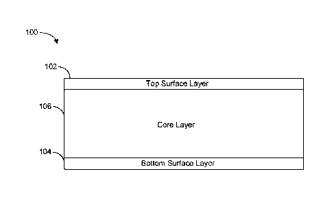
[0022] Referring now to FIG. 1, an example composite board 100 is shown, in
accordance
with some embodiments of the present disclosure. Composite board 100 may be
manufactured to operate as a roof cover board that can provide impact
protection (from
hail, foot traffic, and/or heavy equipment), temporary water resistance, fire
resistance,
-5-
Date Recue/Date Received 2023-09-05
wind-uplift constraint, thermal dimensional stability, and/or flexibility that
is often
required in roofing applications. Composite board 100 may be manufactured such
that
mechanical fasteners can be used to couple composite board 100 to other
components (e.g.,
a wood frame) and/or such that adhesives can be used to adhere other
components to the
outer surfaces of composite board 100.
[0023] Composite board 100 may comprise three discrete layers, a top surface
layer 102,
a bottom surface layer 104, and a core layer 106. Top surface layer 102 and
bottom surface
layer 104 may be made from nylon film, polyester film, cellulose acetate film,
nylon, or
polyester non-woven fabrics, and/or textiles, such as those based on cotton,
or other
materials desirable for the outer surface of the finished composite board 100.
In some
embodiments, the top surface layer 102 and the bottom surface layer 104 may be
about
0.005-0.100" thick. Core layer 106 may be about 0.100-1.500" thick and may
comprise
discrete paper fragments and plastic fragments such as polypropylene or
polyethylene
fragments, which may be connected through the use of a thermoplastic bonding
resin, such
as polyethylene. Core layer 106 may be manufactured by heating and cooling a
mat (e.g.,
mat 204) of discrete paper fragments and plastic fragments as discussed below
with
reference to FIG. 2.
[0024] The structure of composite board 100 may be designed to achieve
compression load
support, sudden impact resistance, wind uplift resistance, fastener retention,
adhesive
zo compatibility, temporary rain protection, low flame spread, thermal
dimensional stability,
and an exceptional level of mechanical flexibility. The design promotes rapid
and easy
installation of the cover board in a commercial low slope roof application. It
may be
especially advantageous in re-roofing applications due to its level of
flexibility, which may
allow it to more easily conform to a curved contour of the perimeter region of
the roof.
The upper (when installed) outer surface of the board may allow for the
absorption of
adhesives but may temporarily resist transfer of rainwater into the core layer
of the board.
[0025] Referring now to FIG. 2, a composite board manufacturing system 200 is
shown,
in accordance with some embodiments of the present disclosure. It should be
understood
that the various components of the composite board manufacturing system 200
are not to
-6-
Date Recue/Date Received 2023-09-05
scale. Further, certain components in the system, including cooling and
cutting
components, are not shown. Composite board manufacturing system 200 may
include a
forming bin 202 configured to receive a mixture of plastic and paper and to
dispense a
continuous mat 204 of paper and plastic onto a conveyor system 206. The
continuous mat
204 may be heated, pressed, and cut to form the core layer 106 of the
composite board 100.
The conveyor system 206, may include one or more belts 208 arranged end to
end, each
belt 208 travelling around two or more rollers 210. One or more of the rollers
210 may be
driven, for example, by a motor or engine. The conveyor system 206 moves the
continuous
mat 204 through the various stages of manufacturing of the composite board
100. As used
.. herein, the term "downstream" refers to the direction that the conveyor
system 206 moves
the continuous mat 204, and the term "upstream" refers to a direction opposite
the direction
that the conveyor system 206 moves the continuous mat 204. Lower facers 212
may be
inserted from underneath the conveyor system 206 such that the lower facers
212 are
positioned between the continuous mat 204 and the conveyor belt 208. In some
embodiments, the lower facers 212 may be positioned on the conveyor system 206
upstream of the forming bin 202, such that the continuous mat 204 is deposited
directly
onto the lower facers 212. Upper facers 214 may be positioned on top of the
continuous
mat 204 to form a composite sandwich 216 including the continuous mat 204
sandwiched
between the lower facers 212 and the upper facers 214. Thus, when the
continuous mat
zo 204 is pressed, cooled, and cut, a lower facer 212, or a portion of a
lower facer 212, may
form the bottom surface layer 104 of the composite board 100. The upper facer
214, or a
portion of the upper facer 214, may form the top surface layer 102 of the
composite board.
In some embodiments, only the upper facers 214 or only the lower facers 212
may be
added, such that the finished composite board 100 does not include either a
top surface
layer 102 or a bottom surface layer 104. In some embodiments, the mat of paper
and plastic
that is pressed to form the core layer 106 may not be continuous. For example,
the core
layer 106 material may be deposited on to the conveyor belt 208 with periodic
interruptions
if needed for manufacturability.
[0026] After the lower facers 212 and/or the upper facers 214 are positioned
respectively
underneath and on top of the continuous mat 204, the conveyor system 206 may
move the
-7-
Date Recue/Date Received 2023-09-05
composite sandwich 216 to a hot press assembly 218. The hot press assembly 218
may
include heated belts 220, each travelling around two or more rollers 222 in a
continuous
circuit, positioned above and below the composite sandwich 216. One or more of
the
rollers 222 may be driven, for example, by a motor or engine. In some
embodiments, the
heated belts 220 may be made of steel. The heated belt 220 may be heated to a
temperature
in the range of about 350 degrees Fahrenheit to about 480 degrees Fahrenheit.
A heating
element (e.g., a resistive heating element, an inductive heating element,
etc.) may be placed
in contact with or in proximity to the heated belt 220 to heat the heated belt
220 to the
desired temperature. For example, a resistive heating element may be
positioned between
the upper and lower segments of each heated belt 220 or adjacent the segment
of the heated
belt 220 not in contact with the composite sandwich 216. In some embodiments,
the rollers
222 may include heating elements, and heat may be transferred from the rollers
222 to the
heated belts 220. The system 200 may include temperature sensors to measure
the
temperatures of the heated belts 220. The measurements can be used to control
the heating
elements to maintain the heated belts 220 at the desired temperature. The
heated belts 220
and rollers 222 may function similarly to the conveyor system 206, with the
rollers 222
being configured to drive the heated belts 220 to move the composite sandwich
216
continuously through the hot press assembly 218. At the same time, the heated
belts 220
and rollers 222 apply heat and high pressure to melt the plastic in the
continuous mat 204
zo and compress the composite sandwich 216. In some embodiments, there may
be only one
heated belt 220 either above or below the composite sandwich 216, with the
other side of
the composite sandwich 216 not being heated. In these embodiments, a non-
heated belt
(e.g., similar to conveyor belt 208) may be used to apply pressure, but not
heat, to the
opposite side of the composite sandwich. As discussed above, plastic from the
continuous
mat 204 that comes into contact with the heated belts 220 may burn and stick
onto the
heated belts 220. This can cause damage to the heated belts 220 and can affect
the quality
of the finished composite board 100.
[0027] To reduce or prevent the burning and sticking of plastic to the heated
belts 220, the
hot press assembly 218 may include a non-stick belt 224 positioned between
each heated
belt 220 and the composite sandwich 216, thus separating each heated belt 220
from at
-8-
Date Recue/Date Received 2023-09-05
least a portion of the composite sandwich 216. In some embodiments, the non-
stick belt
224 may be a looped belt surrounding the heated belt 220. Each non-stick belt
224 may be
guided by additional rollers 226 around a continuous circuit surrounding the
circuit
traveled by a heated belt 220 to continuously return the non-stick belt 224 to
the upstream
side of the hot press assembly 218. In some embodiments, the additional
rollers 226 may
be unpowered idler rollers, and the non-stick belts 224 may not be configured
to be driven
independently of the heated belts 220. The non-stick belt 224 may be
compressed between
the heated belt 220 and the composite sandwich 216 and moved along the hot
press
assembly 218 by the heated belt 220 via friction. For example, as discussed
above, one or
.. more of the rollers the rollers 222 connected to each heated belt 220 may
be powered by a
motor or engine. The rotation of the rollers 222 may cause the heated belt 220
to travel in
a circuit around the rollers. The distance between the non-stick belts 224
above and below
the composite sandwich 216 may be less than the height of the composite
sandwich 216.
Thus, when the composite sandwich 216 is fed into the upstream side of the hot
press
assembly 218, the layers of the composite sandwich 216 may be compressed, and
the non-
stick belts 224 may be pressed between the heated belts 220 and the composite
sandwich
216. The heated belts 220 may then move both the composite sandwich 216 and
the non-
stick belts 224 toward the downstream end of the hot press assembly 218. The
non-stick
belts 224 may maintain separation between the composite sandwich 216 and the
heated
zo belts 220, thus preventing or reducing the sticking of plastic to the
heated belts 220. After
the composite sandwich 216 exits the hot press assembly 218, the composite
sandwich 216
can be cooled and cut into various shapes and sizes.
[0028] Referring now to FIG. 3, a composite sandwich 216 is shown from above
on a
portion of a conveyor system 206, in accordance with some embodiments of the
present
disclosure. The composite sandwich 216 is shown prior to being heated and
pressed by the
hot press assembly 218. The conveyor belt 208 may have first width Wl, and the
continuous mat 204 may have a second width W2 that is less than the width W1
of the
conveyor belt 208. For example, the belt may have a width W1 of about 110
inches, and
the continuous mat 204 may have a width W2 of about 100 inches. As shown in
FIGS. 4-
6, the heated belts 220 may have a width W6 that is approximately equal to
width W1 of
-9-
Date Recue/Date Received 2023-09-05
the conveyor belt 208. The conveyor system may include side plates 227 on
either side of
the belt 208 to stop any of the paper and plastic material of the continuous
mat 204 from
falling off the sides of the belt 208. When the continuous mat 204 is
compressed by the
hot press assembly 218, the continuous mat 204 materials are displaced and
squeezed
toward the sides of the lower and upper facers 212, 214. Thus, it may be
desirable for the
outside edges of the upper facers 214 and the lower facers 212 (not visible in
FIG. 3) to
extend beyond the outside edges of the continuous mat 204 by a distance Dl.
The distance
D1 may be about 1 inch to about 7 inches to stop the plastic in the continuous
mat 204 from
seeping out the sides of facers 212, 214 and contacting the heated belts 220
when the
to composite sandwich 216 is compressed. If the continuous mat 204 is about
100 inches
wide, for example, facers 212, 214 with a width of about 105 inches may be
desirable.
However, many materials that can be used for the facers 212, 214 may not
generally be
commercially available in that width. For example, fiberglass facers may be
available with
a maximum width of about 49 inches to about 52 inches.
[0029] In some embodiments, the forming bin 202 may dispense the materials of
the
composite mat 204 with the composite mat 204 having an uncompressed width. The
hot
press assembly 218 may compress the composite mat 204 to a compressed width
that may
be wider than the uncompressed width. Material in the composite mat may spread
outward
as it is compressed and the thickness of the mat 204 decreases. The width W2
of the
.. composite mat 204 discussed herein may refer to the compressed width.
[0030] To manufacture composite boards 100 using commercially available
materials for
facers, while using as much of the width W1 of the conveyor belt 208 as
possible, two
upper facers 214 may be laid on top of the continuous mat 204 side-by-side,
and two lower
facers 212 may be positioned under the continuous mat 204 side-by side, as
shown in FIG.
3. In some embodiments, the side-by-side facers 212, 214 may overlap at the
center to stop
plastic from the continuous mat 204 from seeping through the seams between the
side-by-
side facers 212, 214 and contacting the heated belt 220. However, even with
facers 212,
214 that are 52 inches wide, which may be the widest commercially available
size, any
overlap would reduce the combined width to less than 104 inches, which may not
be
-10-
Date Recue/Date Received 2023-09-05
enough to prevent plastic seepage at the outer edges of the facers 212, 214.
Further,
moisture in the continuous mat 204 may flash to steam when the composite
sandwich 216
is heated and pressed. While some facers 212, 214 may be made from materials
porous
enough that at least some steam can escape through the facers themselves, in
some
embodiments, steam may escape primarily from around the edges of the facer
212, 214.
With the side-by-side facers 212, 214 overlapping, the steam would only be
able to escape
via the outer edges of the facers 212, 214. Steam near the center of the
continuous mat 204
would thus need to travel nearly 52 inches to escape from the mat 204. In some
cases, the
steam could push the facers 212, 214 away from the continuous mat 204, causing
to separation between the continuous mat 204 and the facers 212, 214 or
causing distortion
of the composite sandwich 216, affecting the quality of the finished composite
boards 100.
[0031] In some embodiments, the side-by-side facers 212, 214 may be butted up
against
each other without overlapping. This may allow some steam to escape via the
seam
between the side-by-side facers 212, 214 at the center of the continuous mat
204. However,
depending on the combined overall width W3 of the facers 212, 214 (defined as
the distance
from a left outside edge of a leftmost facer 212, 214 to a right outside edge
of a rightmost
facer 212, 214), this may not provide enough distance D1 to prevent plastic
seepage from
the outside edges. For example, if a target overall width W3 of 105 inches is
desired, two
52-inch-wide facers 212, 214 butted up against each other would still not
reach the desired
width W3. As shown in FIG. 3, the side-by-side facers 212, 214 may be arranged
with a
gap 228 therebetween. This may allow for steam to escape more easily through
the gap
228 and can provide a large enough overall width W3 to prevent plastic seepage
from the
outer edges of the facers 212, 214. However, this leaves a strip of the
continuous mat 204
in the gap 228 exposed to the heated belts 220. It should be understood that
only four upper
facers 214 are shown in FIG. 3 in order to better illustrate the placement of
the facers 212,
214 on the continuous mat 204. However, a substantially continuous row of
facers 212,
214 may be inserted above and below the continuous mat 204 as it moves along
the
conveyor system 206.
-11 -
Date Recue/Date Received 2023-09-05
[0032] Referring now to FIG. 4, a section view of a composite sandwich 216
within a hot
press assembly 218 is shown, in accordance with some embodiments of the
present
disclosure. Again, it should be understood that the components are not to
scale, and certain
components of the system are omitted for clarity. As shown in FIG. 4, the non-
stick belts
224 are wide enough to cover the gap 228 between the upper facers and the gap
228
between the lower facers, but do not cover the entire heated belts 220 or the
entire facers
212, 214. More specifically, the non-stick belt 224 has a width W4 that is
larger than the
width W5 of the gaps 228 between the facers 212, 214, but is smaller than the
overall width
W3 of the facers 212, 214 and the width W6 of the heated belts 220. A non-
stick belt 224
of this size may be sufficient to prevent plastic in the continuous mat 204
from contacting
the heated belts 220 through the gap 228 while minimizing the size and cost of
the non-
stick belt 224. Due to the gaps 228 in the facers 212, 214, steam is allowed
to escape from
the continuous mat 204 through the gaps 228, as well as from the edges 230 of
the
composite sandwich 216.
[0033] As an example of the above, the heated belts 220 may have a width W6 of
approximately 110 inches. The continuous mat 204 may be approximately 100
inches
wide, and each facer 212, 214 may be approximately 52 inches wide. The gap 228
may
have a width W4 between about one half inch and about 6 inches, resulting in
overall facer
width W4 of about 104.5 inches to about 110 inches. Thus, the distance D1 from
the
outside edge of the facers 212, 214 may be between about 2.25 inches to about
5 inches on
each side. The non-stick belt 224 may have a width W5 that is at least as wide
as the width
W4 of the gap 228 and that may be up to about 6 inches wider than the width W4
of the
gap 228. The width W for the gap 228 can be adjusted based on the expected
expansion
of the continuous mat 204 when the composite sandwich 216 is compressed. For
example,
if the continuous mat 204 is expected to expand to a width of 106 inches when
the
composite sandwich 216 is compressed, the gap 228 between the facers 212, 214
may be
set at approximately 2 inches or more, resulting in an overall facer width W3
of
approximately 106 inches or more, so that plastic in the continuous mat 204
does not seep
around the edges of the facers 212, 214. It should be understood that although
FIGS. 3 and
4 show two rows of lower facers 212 and two rows of upper facers 214, in some
-12-
Date Recue/Date Received 2023-09-05
embodiments, there may be more rows of facers 212, 214. For example, if the
composite
board manufacturing system 200 may be operated with three rows of lower facers
212 and
three rows of upper facers 214, resulting in two gaps 228 in the lower facers
212 and two
gaps 228 in the upper facers 214. The hot press assembly 218 may include four
non-stick
belts 224, with one non-stick belt 224 positioned above each gap 228.
Alternatively, the
hot press assembly 218 may include one non-stick belt 224 wide enough to cover
both of
the lower gaps 228 and the center lower facer 212, and the second non-stick
belt 224 wide
enough to cover both of the upper gaps 228 and the center upper facer 214.
[0034] The non-stick belts 224 may include a material or materials to which
melted plastic
to from the continuous mat 204 does not or cannot adhere. Thus, when the
composite
sandwich 216 exits the hot press assembly 218, substantially no plastic
residue may remain
on the non-stick belts 224. For example, the non-stick belts 224 may be made
from, may
include, may be a composite of, may be lined with, or may be coated with
PTIHE, PFA, or
FEP. For example, the non-stick belts 224 may be made from or include a PTFE
composite
.. that is porous enough to allow steam to escape through the material of the
non-stick belts
224. Steam can thus escape from the continuous mat 204 through the gap 228
between the
facers 212, 214 and then into and through the non-stick belts 224. Steam that
escapes form
the composite mat 204 may also travel along the gap 228 and escape at the
upstream and
downstream ends of the heated belts 220.
zo .. [0035] Referring now to FIG. 5, a section view of a composite sandwich
216 within a hot
press assembly 218 is shown, in accordance with some embodiments of the
present
disclosure. Again, it should be understood that the components are not to
scale, and certain
components of the system are omitted for clarity. As shown in FIG. 4, the hot
press
assembly 218 may include non-stick edge belts 232 in addition to the non-stick
belts 224.
The non-stick edge belts 232 may protect the heated belts 220 from contact
with plastic
that may seep out of the continuous mat 204 around the outside edges of the
facers 212,
214. Again, this may reduce the cost of protecting the heated belt 220 and the
weight of
the hot press assembly 218 compared to a non-stick belt 224 that covers the
entire heated
belt 220. In these embodiments, the width W5 of the gap 228 does not
necessarily have to
-13-
Date Recue/Date Received 2023-09-05
be increased to account for the expansion of the continuous mat 204 when the
composite
sandwich 216 is compressed. For example, if the continuous mat 204's expected
to expand
to a width of 106 inches, the width W5 of the gap 228 can be set at 1 inch,
resulting in an
overall facer width of 105 inches if the facers 212, 214 are 52 inches wide,
and any plastic
from the continuous mat 204 that seeps around the edges of the facers 212, 214
will remain
separated from the heated belts 220 by the non-stick edge belts 232. In some
embodiments,
the facers 212, 214 may be butted up against one another without a gap 228 and
the hot
press assembly 218 may include non-stick edge belts 232 without a center non-
stick belt
224. In some embodiments, non-stick edge belts 232 may be included when only
one facer
212, 214 is used on each of the top and bottom of the mat 204, rather than two
facers 212,
214 arranged side by side.
[0036] Referring now to FIG. 6, a section view of a composite sandwich 216
within a hot
press assembly 218 is shown, in accordance with some embodiments of the
present
disclosure. Again, it should be understood that the components are not to
scale, and certain
.. components of the system are omitted for clarity. In the embodiment shown
in FIG. 6, the
non-stick belts 224 are wider than the overall width W3 of the facers 212,
214. The non-
stick belts 224 may thus separate the entire facers 212, 214, the gaps 228
between the facers
212, 214, and a region beyond the edges of the facers 212, 214 from the heated
belt 220.
In some embodiments, the non-stick belts 224 may have a width W4 that is
approximately
equal to the width W3 of the heated belts 220, such that the entire heated
belts 220 can be
protected from contact with any plastic moving through the hot press assembly
218. In
some embodiments, the non-stick belts 224 may have a width W4 that is larger
or smaller
than the width W6 of the heated belts 220, but still larger than the overall
width W3 of the
facers 212, 214. In these embodiments, the non-stick belts 224 may protect the
heated belts
.. 220 from contact with plastic that seeps through the gaps 228 between the
facers 212, 214
and around the edges 230 of the composite sandwich. In embodiments in which
the facers
212, 214 are porous, the non-stick belts 224 may protect the heated belts 220
from contact
with plastic that seeps through the facers 212, 214 themselves. As discussed
above, the
facers 212, 214 and the non-stick belts 224 may be porous such that steam from
the
-14-
Date Recue/Date Received 2023-09-05
continuous mat 204 can escape through the facers 212, 214 and through non-
stick belts
224.
[0037] Referring now to FIG. 7, a section view of a composite sandwich 216
within a hot
press assembly 218 is shown, in accordance with some embodiments of the
present
disclosure. Again, it should be understood that the components are not to
scale, and certain
components of the system are omitted for clarity. In the embodiment shown in
FIG. 7, the
hot press assembly 218 does not include non-stick belts 224. Instead, the
heated belts 220
may include a non-stick coating 234. The non-stick coating 234 may cover all
or only a
portion of the heated belt 220, similar to the non-stick belt 224 and the non-
stick edge belts
to .. 232. In some embodiments, the non-stick coating 234 may be made from
PTFE, PFA,
FEP, or chrome. Due to manufacturing limitations, the non-stick coating 234
may be
applied to the entire heated belt 220 including surfaces that do not contact
the composite
sandwich 216, such as the edges of the heated belt 220 and the surface of the
heated belt
220 opposite the surface that contacts the composite sandwich 216. For
example, the entire
heated belt 220 may be submerged in a bath that coats every surface of the
heated belt 220
with the non-stick coating 234 before the belt is installed in the hot press
assembly 218.
[0038] Referring now to FIG. 8, a section view of a composite sandwich 216
within a hot
press assembly 218 is shown, in accordance with some embodiments of the
present
disclosure. Again, it should be understood that the components are not to
scale, and certain
zo components of the system are omitted for clarity. In the embodiment
shown in FIG. 7, the
hot press assembly 218 includes a stationary press 236 with a base 238 and an
upper portion
240. The base 238 and the upper portion 240 may each include a hot platen 242.
The
upper portion 240 may be configured to be raised and lowered using, for
example,
hydraulic pressure. The conveyor system 206 may move the composite sandwich
216 onto
the hot platens 242 of the base 238, and the upper portion 240 may be lowered
and pressed
onto the composite sandwich 216 such that the hot platens 242 heat and
compress the
composite sandwich 216. The conveyor system 206 or an actuator may then move
the
composite sandwich 216 out of the stationary press 236 before repeating the
process on
another composite sandwich 216 or another portion of a continuous composite
sandwich
-15-
Date Recue/Date Received 2023-09-05
216. In some embodiments, the stationary press 236 may include one or more non-
stick
belts 224 positioned between the lower hot platen 242 and the composite
sandwich 216.
Similar to the arrangement of the non-stick belt 224 shown in FIG. 2, the non-
stick belt
224 may travel around a circuit of rollers 226. The circuit may carry the non-
stick belt 224
all the way around the base 238. The floor 244 supporting the base 238 may
include a
cavity to allow the non-stick belt 224 to pass underneath the base 238. One or
more of the
rollers 226 may be powered, for example by a motor or an engine, to drive the
non-stick
belt 224. The lower non-stick belt 224 may thus assist the conveyor system 206
in moving
the composite sandwich 216 through the hot press assembly.
to [0039] Because the upper portion 240 of the stationary press 236 is
lifted when the
composite sandwich 216 is removed from the stationary press 236, the upper
portion 240
may not require a non-stick belt 224 arranged in a circuit around the upper
portion 240.
For example, the upper hot platen 242 may be coated with a non-stick coating
234. In
some embodiments, however, the stationary press 236 may include a non-stick
belt 224
arranged in a circuit around the upper portion 240. The non-stick belt 224
arranged around
the upper portion 240 of the stationary press 236 may be driven by one or more
rollers 226.
When the upper portion 240 is lifted, the non-stick belt 224 may be driven
partially around
the circuit such that a different portion of the non-stick belt 224 is pressed
by the stationary
press 236 in each successive pressing, which may extend the life of the non-
stick belt 224.
In some embodiments, after the composite sandwich 216 has been pressed, the
upper
portion 240 of the stationary press 236 may partially lift such that the upper
non-stick belt
224 is still in contact with the composite sandwich 216 but applying a reduced
amount of
pressure. The upper and lower non-stick belts 224 may then cooperatively drive
the
composite sandwich 216 out of the stationary press 236. In other embodiments,
the upper
portion 240 of the stationary press 236 may lift such that the upper non-stick
belt 224 is no
longer in contact with the composite sandwich 216, and the lower non-stick
belt 224 may
drive the composite sandwich 216 out of the stationary press 236.
[0040] Referring now to FIG 9, a block diagram of a composite board
manufacturing
system 500 is shown, in accordance with some embodiments of the present
disclosure. The
-16-
Date Recue/Date Received 2023-09-05
composite board manufacturing system 500 may be similar or equivalent to the
composite
board manufacturing system 200, shown and described with reference to FIG. 2.
Composite board manufacturing system 500 may include a manufacturing apparatus
502
and a controller 504. Controller 504 may be a component of manufacturing
apparatus 502
(e.g., a processor and/or display coupled to manufacturing apparatus 502) or
may be
external to manufacturing apparatus 502. Manufacturing apparatus 502 may
include a
forming bin 506 (e.g., similar or equivalent to the forming bin 202), a
conveyor system 508
(e.g., similar or equivalent to the conveyor system 206), a hot press assembly
510 (e.g.,
similar or equivalent to the hot press assembly 218), a cold press assembly
512, sensors
to 514, and a cutting assembly 515. Controller 504 may be configured to
operate
manufacturing apparatus 502 to manufacture composite boards 100. In some
instances,
controller 504 may receive sensor data from sensors 514 that indicate one or
more
characteristics of a composite sandwich 216 and/or the manufacturing apparatus
502 and
may adjust the operation of manufacturing apparatus 502 based on the sensor
data (e.g.,
adjust a speed of a conveyor belt of conveyor system 508, a temperature of the
heated belts
of the hot press assembly 510, a temperature of the belts of the cold press
assembly 512,
etc.). For example, measurements from a temperature sensor configured to
measure the
temperature of a heated belt (e.g., heated belt 220) may be used to adjust the
temperature
of the belt. Measurements from a moisture sensor configured to measure the
moisture
zo content of a pressed composite sandwich 216 may be used to adjust the
speed of the
conveyor system 508 and the heated belts 220.
[0041] Controller 504 may include a processing circuit 516 and a communication
interface
522. Processing circuit 516 may include a memory 518 and a processor 520, in
some
embodiments. Processing circuit 516 may be implemented as a general-purpose
processor,
an application specific integrated circuit ("ASIC"), one or more field
programmable gate
arrays ("FPGAs"), a digital-signal-processor ("DSP"), circuits containing one
or more
processing components, circuitry for supporting a microprocessor, a group of
processing
components, or other suitable electronic processing components. Processor 520
may
include an ASIC, one or more FPGAs, a DSP, circuits containing one or more
processing
components, circuitry for supporting a microprocessor, a group of processing
components,
-17-
Date Recue/Date Received 2023-09-05
or other suitable electronic processing components. In some embodiments,
processor 520
may execute computer code stored in memory 518 to facilitate the activities
described
herein. Memory 518 may be any volatile or non-volatile computer-readable
storage
medium capable of storing data or computer code relating to the activities.
According to
some embodiments, memory 518 may include computer code modules (e.g.,
executable
code, object code, source code, script code, machine code, etc.) for execution
by processor
520.
[0042] Communication interface 522 may communicate with a communication
interface
524 of manufacturing apparatus 502 via any synchronous or asynchronous
network.
Communication interface 522 may include one or more communication interfaces
that can
communicate with the components of manufacturing apparatus 502. For example,
controller 504 may receive data from sensors 514 and/or control conveyor
system 508, hot
press assembly 510, and/or cold press assembly 512 via communication interface
522.
Based on such sensor data and via communication interface 522, controller 504
may
transmit signals to the manufacturing apparatus 502 or devices (e.g.,
actuators or
controllers) that operate the individual components 506-515 to cause
manufacturing
apparatus 502 to form a composite sandwich 216 and move the composite sandwich
216
on conveyor system 508 (e.g., by moving a conveyor belt of conveyor system
508) through
the hot press assembly 510 and/or the cold press assembly 512, for example, by
controlling
the speed of a motor to rotate a roller configured to drive the conveyor belt.
Similarly, the
controller 504 may control the speed of a motor to rotate a roller configured
to drive a
heated belt of the hot press assembly 510. If the system includes a stationary
press, the
controller 504 may be configured to control a hydraulic or other linear
actuator to raise and
lower an upper portion of the hot press to compress a composite sandwich 216.
The
controller 504 may also be configured to control a saw and one or more
actuators of the
cutting assembly 515 to cut the composite sandwich 216 into finished composite
boards
100.
[0043] FIG. 10 is a diagram of an example process 700 for forming a composite
board 100,
in accordance with some embodiments of the present disclosure. Process 700 can
be
-18-
Date Recue/Date Received 2023-09-05
performed using a composite board manufacturing system (e.g., composite board
manufacturing system 200, 500), which may include a controller (e.g.,
controller 504).
Process 700 may include more or fewer operations, and the operations may be
performed
in any order. Performance of process 700 may enable the composite board
manufacturing
system 200, 500 to manufacture, from waste materials, a composite board 100.
[0044] At operation 702 of the process 700, a mat of paper and plastic may be
formed, for
example, by continuously depositing a mat of paper and plastic on a conveyor
belt of a
conveyor system. For example, the forming bin 202 may deposit a continuous mat
204
onto a conveyor belt 208 of the conveyor system 206. The controller 504 may
control the
to rate at which the forming bin 202 deposits material to form the
continuous mat 204, for
example, by controlling an actuator to widen or narrow an outlet valve of the
forming bin
202. The controller 504 may simultaneously control a motor to rotate one or
more rollers
to ten of the conveyor system 206 to move the continuous mat 204 along the
belt 208.
[0045] At operation 704 of the process 700, one or more lower facers may be
inserted
below the continuous mat and/or one or more upper facers may be inserted on
top of the
continuous mat to form a composite sandwich. For example, the lower facers 212
may be
inserted between conveyor belts 208 underneath the continuous mat 204, and/or
the upper
facers 214 may be inserted on top of the continuous mat 204 to form a
composite sandwich
216. The controller 504 may control one or more actuators or motors to insert
the facers
zo 212, 214 above and/or below the continuous mat 204. In some embodiments,
two lower
facers 212 may be positioned side-by-side below the continuous mat 204.
Similarly, two
upper facers 214 may be positioned side-by-side on top of the continuous mat
204. Each
pair of facers 212, 214 may overlap, may butt up against each other, or may
have a gap
therebetween. In some embodiments, facers may only be positioned on one side
of the mat
(e.g., above or below the mat).
[0046] At operation 706 of the process 700, the composite sandwich may be
heated and
compressed by a hot press assembly including a heated belt, while maintaining
physical
separation between the heated belt and at least a first portion of the
composite sandwich.
For example, physical separation may be maintained between the heated belt and
the
-19-
Date Recue/Date Received 2023-09-05
composite sandwich in portions of the composite sandwich where plastic seepage
from the
continuous mat is likely to occur. For example, the composite sandwich 216 may
be
inserted into the hot press assembly 218 and compressed by the heated belts
220 positioned
above and below the composite sandwich 216. Separation between the heated belt
220 and
portions of the composite sandwich 216 where plastic is likely to seep out
from the
continuous mat 204 may be maintained by positioning a non-stick belt 224
between the
heated belt 220 and the composite sandwich 216 or by applying a non-stick
coating to the
heated belt 220. For example, when two lower facers 212 and two upper facers
214 are
each positioned side-by-side with a gap therebetween, the non-stick belts 224
may be
o positioned between the gaps and the heated belts 220. The non-stick belts
224 may
maintain separation between the heated belts 220 and the gaps and edges of the
facers 212,
214 while not maintaining separation between the heated belts 220 and the
entirety of the
facers 212, 214. Non-stick belts 224 may maintain separation between the
heated belts
220 and the outside edges of the facers 212, 214, where plastic from the
continuous mat
may seep out from the edges, without maintaining separation between the heated
belts 220
and the entirety of the facers 212, 214. In some embodiments, the non-stick
belts 224 may
be sized and positioned such that the heated belts 220 are entirely separated
from and do
not come into contact with the composite sandwich 216. For example, if the
facers 212,
214 are porous, the non-stick belts 224 may maintain separation between the
facers 212,
zo 214 and the heated belts 220 as well as between the mat 204 and the
heated belts 220. The
non-stick belts 224 may be wider than the overall combined width of adjacent
facers 212,
214, including any gap therebetween. As discussed above, a nonstick coating
may be
applied to the heated belts 220 to maintain separation between the heated
belts 220 and the
composite sandwich 216, rather than using non-stick belts 224. The controller
504 may
control a motor to rotate a roller (e.g., a roller 222) to drive the heated
belt 220 and move
the composite sandwich through the hot press assembly 218.
[0047] At operation 708 of the process 700, the composite sandwich may be
cooled by a
cold press assembly (e.g., cold press assembly 512). The controller 504 may
control one
or more motors or actuators of a cold press to apply cooling plates to the
composite
sandwich 216 to solidify the continuous mat 204. At operation 710 of the
process 700, the
-20-
Date Recue/Date Received 2023-09-05
composite sandwich may be cut into composite boards by a cutting assembly. For
example,
the controller 504 may control motors and actuators of the cutting assembly
515 to cause
one or more saws of the cutting assembly 515 to cut the composite sandwich 216
into
finished composite boards 100. As discussed above, the facers 212, 214 may be
between
approximately 49 inches wide and 52 inches wide, and the continuous mat 204
may be
approximately 100 inches wide. Two lower facers 212 may be positioned side-by-
side
underneath the continuous mat 204, and two upper facers 214 may be positioned
side-by-
side the top of the continuous mat 204. When the composite sandwich 216 is
compressed,
the continuous mat 204 may expand in width, such that the continuous mat 204
extends
nearly to or beyond the outside edges of the facers 212, 214. The cutting
assembly 515
can cut the composite sandwich 216 into composite boards 100 with a finished
width of,
for example, about 48 inches by trimming the inside and/or outside edges of
the facers 212,
214. The continuous mat 204 material that was positioned in the gaps 228
between the
facers 212, 214 or that extended beyond the outside edges of the facers can be
trimmed off
and discarded or recycled.
[0048] In an aspect, a system for producing a composite board comprising
plastic and
paper is provided. The system includes a hot press assembly. The hot press
assembly
includes a first heated belt configured to apply heat and pressure to a
composite
sandwich. The composite sandwich includes a mat comprising a mixture of paper
and
plastic and at least one facer positioned above or below the mat. The hot
press assembly
further includes a roller configured to drive the first heated belt to move
the composite
sandwich through the hot press assembly and a first non-stick belt configured
to separate
at least a portion of the composite sandwich from the first heated belt as the
composite
sandwich is moved through the hot press assembly.
[0049] In some embodiments, the hot press assembly further includes a second
heated
belt configured to apply heat and pressure to the composite sandwich in
cooperation with
the first heated belt, wherein one of the first heated belt or the second
heated belt is
positioned above the mat, and the other of the first heated belt or the second
heated belt is
positioned below the mat, and a second non-stick belt configured to separate
at least a
-21-
Date Recue/Date Received 2023-09-05
second portion of the composite sandwich from the second heated belt as the
composite
sandwich is moved through the hot press assembly.
[0050] In some embodiments, the first heated belt comprises a material to
which melted
plastic does not adhere. In some embodiments, the material is PTFE.
[0051] In some embodiments, the first heated belt has a first width, and the
first non-stick
belt has a second width that is approximately equal to the second width.
[0052] In some embodiments, the first non-stick belt is configured to separate
an exposed
portion of the mat between two adjacent facers from the first heated belt
without
separating the entirety of either of the two adjacent facers from the first
heated belt. In
io some embodiments, the hot press assembly further comprises a second non-
stick belt
configured to separate an outside edge of one of the two adjacent facers from
the first
heated belt without separating the entirety of either of the two adjacent
facers from the
first heated belt.
[0053] In some embodiments, the first heated belt is configured to travel
around a first
circuit and the first non-stick belt is configured to travel around a second
circuit
surrounding the first circuit. In some embodiments, the first heated belt is
configured to
press the first non-stick belt against the composite sandwich such that the
first non-stick
belt travels along the second circuit as the composite sandwich moves through
the hot
press assembly. In some embodiments, the first non-stick belt is not
configured to be
zo driven independently of the first heated belt.
[0054] In some embodiments, the system further includes a forming bin
configured to
receive shredded paper and shredded plastic and to dispense the mat and a
conveyor
system. The conveyor system includes a conveyor belt configured to receive the
mat
dispensed from the forming bin and to move the mat toward the hot press
assembly and a
conveyor roller configured to drive the conveyor belt wherein the forming bin
is
configured to dispense the mat onto the conveyor belt. In some embodiments,
the
forming bin is configured to dispense the mat with the mat having an
uncompressed
width, the hot press assembly is configured to press the mat to a compressed
width, and
-22-
Date Recue/Date Received 2023-09-05
the first non-stick belt has a third width that is greater than the compressed
width of the
mat. In some embodiments, the system further includes a cold press configured
to cool
the composite sandwich after the composite sandwich is heated and pressed by
the hot
press assembly and a saw configured to cut the composite sandwich after the
composite
sandwich is cooled to form a finished composite board.
[0055] In another aspect, a method of forming a composite board comprising
paper and
plastic is provided. The method includes forming a composite sandwich
comprising a
mat of paper and plastic positioned on top of or beneath at least one facer
and
compressing the composite sandwich between an upper heated belt and a lower
heated
belt while maintaining physical separation between the heated belts and a
first portion of
the composite sandwich.
[0056] In some embodiments, forming the composite sandwich comprises
positioning
two facers side-by-side with a gap therebetween, and wherein the first portion
of the
composite sandwich comprises the gap. In some embodiments, physical separation
is not
maintained between the heated belts and the entirety of the two facers.
[0057] In some embodiments, wherein the first portion of the composite
sandwich
comprises an outer edge of at least one of the facers.
[0058] In some embodiments, the at least one facer is porous and the first
portion of the
composite sandwich comprises an outer surface of each facer.
[0059] In some embodiments, maintaining physical separation between the heated
belts
and the portion of the composite sandwich comprises positioning at least one
non-stick
belt between the upper heated belt or the lower heated belt and the composite
sandwich.
In some embodiments, the at least one facer has an overall width measured from
a left
edge of a leftmost facer to a right edge of a rightmost facer, and the first
non-stick belt
has a third width that is greater than the overall width of the at least one
facer.
[0060] While this specification contains specific implementation details,
these should not
be construed as limitations on the scope of what may be claimed but rather as
descriptions
-23-
Date Recue/Date Received 2023-09-05
of features specific to particular implementations. Certain features described
in this
specification in the context of separate implementations can also be
implemented in
combination in a single implementation. Conversely, various features described
in the
context of a single implementation can also be implemented in multiple
implementations
separately or in any suitable sub-combination. Moreover, although features may
be
described as acting in certain combinations and even initially claimed as
such, one or more
features from a claimed combination can, in some cases, be excised from the
combination,
and the claimed combination may be directed to a sub-combination or variation
of a sub-
combination.
.. [0061] As utilized herein with respect to structural features (e.g., to
describe shape, size,
orientation, direction, relative position, etc.), the terms "approximately,"
"about,"
"substantially," and similar terms are meant to cover minor variations in
structure that may
result from, for example, the manufacturing or assembly process and are
intended to have
a broad meaning in harmony with the common and accepted usage by those of
ordinary
skill in the art to which the subject matter of this disclosure pertains.
Accordingly, these
terms should be interpreted as indicating that insubstantial or
inconsequential
modifications or alterations of the subject matter described and claimed are
considered to
be within the scope of the disclosure as recited in the appended claims.
[0062] The term "coupled" and variations thereof, as used herein, means the
joining of two
members directly or indirectly to one another. Such joining may be stationary
(e.g.,
permanent or fixed) or moveable (e.g., removable or releasable). Such joining
may be
achieved with the two members coupled directly to each other, with the two
members
coupled to each other using a separate intervening member and any additional
intermediate
members coupled with one another, or with the two members coupled to each
other using
an intervening member that is integrally formed as a single unitary body with
one of the
two members. If "coupled" or variations thereof are modified by an additional
term (e.g.,
directly coupled), the generic definition of "coupled" provided above is
modified by the
plain language meaning of the additional term (e.g., "directly coupled" means
the joining
of two members without any separate intervening member), resulting in a
narrower
-24-
Date Recue/Date Received 2023-09-05
definition than the generic definition of "coupled" provided above. Such
coupling may be
mechanical, electrical, or fluidic.
[0063] References herein to the positions of elements (e.g., "top," "bottom,"
"above,"
"below") are merely used to describe the orientation of various elements in
the FIGURES.
It should be noted that the orientation of various elements may differ
according to other
exemplary embodiments, and that such variations are intended to be encompassed
by the
present disclosure.
[0064] The herein described subject matter sometimes illustrates different
components
contained within, or connected with, different other components. It is to be
understood
that such depicted architectures are merely exemplary, and that in fact many
other
architectures can be implemented which achieve the same functionality. In a
conceptual
sense, any arrangement of components to achieve the same functionality is
effectively
"associated" such that the desired functionality is achieved. Hence, any two
components
herein combined to achieve a particular functionality can be seen as
"associated with" each
other such that the desired functionality is achieved, irrespective of
architectures or
intermedial components. Likewise, any two components so associated can also be
viewed
as being "operably connected," or "operably coupled," to each other to achieve
the desired
functionality, and any two components capable of being so associated can also
be viewed
as being "operably couplable," to each other to achieve the desired
functionality. Specific
zo examples of operably couplable include but are not limited to physically
mateable and/or
physically interacting components and/or wirelessly interactable and/or
wirelessly
interacting components and/or logically interacting and/or logically
interactable
components.
[0065] With respect to the use of substantially any plural and/or singular
terms herein,
those having skill in the art can translate from the plural to the singular
and/or from the
singular to the plural as is appropriate to the context and/or application.
The various
singular/plural permutations may be expressly set forth herein for sake of
clarity.
-25-
Date Recue/Date Received 2023-09-05
[0066] It will be understood by those within the art that, in general, terms
used herein, and
especially in the appended claims (e.g., bodies of the appended claims) are
generally
intended as "open" terms (e.g., the term "including" should be interpreted as
"including but
not limited to," the term "having" should be interpreted as "having at least,"
the term
"includes" should be interpreted as "includes but is not limited to," etc.).
It will be further
understood by those within the art that if a specific number of an introduced
claim recitation
is intended, such an intent will be explicitly recited in the claim, and in
the absence of such
recitation no such intent is present. For example, as an aid to understanding,
the following
appended claims may contain usage of the introductory phrases "at least one"
and "one or
more" to introduce claim recitations. However, the use of such phrases should
not be
construed to imply that the introduction of a claim recitation by the
indefinite articles "a"
or "an" limits any particular claim containing such introduced claim
recitation to inventions
containing only one such recitation, even when the same claim includes the
introductory
phrases "one or more" or "at least one" and indefinite articles such as "a" or
"an" (e.g., "a"
and/or "an" should typically be interpreted to mean "at least one" or "one or
more"); the
same holds true for the use of definite articles used to introduce claim
recitations. In
addition, even if a specific number of an introduced claim recitation is
explicitly recited,
those skilled in the art will recognize that such recitation should typically
be interpreted to
mean at least the recited number (e.g., the bare recitation of "two
recitations," without other
zo modifiers, typically means at least two recitations, or two or more
recitations).
Furthermore, in those instances where a convention analogous to "at least one
of A, B, and
C, etc." is used, in general such a construction is intended in the sense one
having skill in
the art would understand the convention (e.g., "a system having at least one
of A, B, and
C" would include but not be limited to systems that have A alone, B alone, C
alone, A and
B together, A and C together, B and C together, and/or A, B, and C together,
etc.). In those
instances where a convention analogous to "at least one of A, B, or C, etc."
is used, in
general such a construction is intended in the sense one having skill in the
art would
understand the convention (e.g., "a system having at least one of A, B, or C"
would include
but not be limited to systems that have A alone, B alone, C alone, A and B
together, A and
C together, B and C together, and/or A, B, and C together, etc.). It will be
further
understood by those within the art that virtually any disjunctive word and/or
phrase
-26-
Date Recue/Date Received 2023-09-05
presenting two or more alternative terms, whether in the description, claims,
or drawings,
should be understood to contemplate the possibilities of including one of the
terms, either
of the terms, or both terms. For example, the phrase "A or B" will be
understood to include
the possibilities of "A" or "B" or "A and B." Further, unless otherwise noted,
the use of
the words "approximate," "about," "around," "substantially," etc., mean plus
or minus ten
percent.
[0067] The foregoing description of illustrative embodiments has been
presented for
purposes of illustration and of description. It is not intended to be
exhaustive or limiting
with respect to the precise form disclosed, and modifications and variations
are possible in
light of the above teachings or may be acquired from practice of the disclosed
embodiments. It is intended that the scope of the invention be defined by the
claims
appended hereto and their equivalents.
-27-
Date Recue/Date Received 2023-09-05