Note : Les descriptions sont présentées dans la langue officielle dans laquelle elles ont été soumises.
FILTER EXTENDER AND FILTER FOR MATING WITH SAME
BACKGROUND
Field of the Disclosure
[0ool] Embodiments of the present disclosure generally relate to a filter
extender
and filter for mating with the same.
Description of the Related Art
[0002] An air filtration system enhances air quality by reducing
impurities, such as
dust, pollen, mold, and bacteria, from the air. The air filtration system has
a holding
frame for mounting an air filter. The air filter may be a bag air filter, a v-
bank air filter,
a deep pleat air filter or other type of air filter. In the case of a v-bank
air filter, the
v-bank air filter has a filter frame for supporting one or more pairs of
filter elements
arranged in a v-configuration (i.e., a v-bank). The filter elements are
comprised of
filtration media configured to remove air impurities. As air flows into the
air filter and
through the filter elements, the air impurities are captured by the v-banks
filtration
media.
[0003] Since the holding frames are permanently installed in a larger
surrounding
structure, such as an air duct of a building ventilation system, the filter
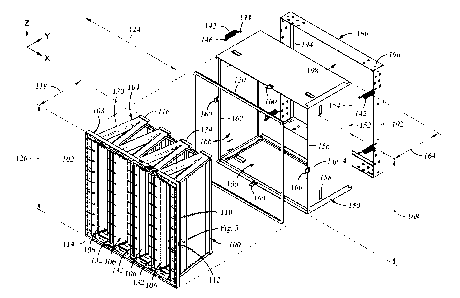
assemblies
are designed to be easily removed from the holding frames when needed for
replacement. Specifically, the filter frame of the air filter is releasably
coupled to the
holding frame. When installed, the filter frame of v-bank air filter is
coupled to the
front end of the holding frame such that the v-banks for filtration media
extend through
and out of the back end of the holding frame.
[0004] In many air filtration systems, the space available behind the
holding frame
is limited, and may interfere with the v-banks for filtration media that
extend out of the
back end of the holding frame. For example, the back end of the holding frame
may
be located close to a wall, cooling coils, or a bend in an air duct, which can
obstruct
1
Date Recue/Date Received 2023-09-20
the v-banks extending out of the back end of the holding frame. Thus in such
installations, the air filter must be either mounted backwards in the holding
frame such
that the v-banks for filtration media that extend out of the front end of the
holding
frame, or the v-bank air filter also requires an additional pre-filter on the
inlet side, it
must include structure that spaces the front of the air filter away from the
front end of
the holding frame such that less or none of the v-banks for filtration media
extend out
of the back end of the holding frame which would allow the attachment of a
additional
prefilter. And structures that space the front of the air filter away from the
front end of
the holding frame necessitate an air filter specifically designed for this
purpose, which
generally increases the cost of manufacturing and stocking due to the special
design.
[0005] Therefore, there is a need for an improved air filter and
associated
components suitable for mounting the air filter in a holding frame of an air
filtration
system.
SUMMARY
[0006] A filter extender and air filter for mating with the same are
provided. The
filter extender is configured to enable an air filter to be mounted to a
filter holding
frame with less or none of the air filter extending through the holding frame.
The filter
extender is also suitable for use with air filters other than the air filter
described herein.
Similarly, the air filter described herein may be utilized with other filter
extenders or
without a filter extender.
[0007] A filter extender that comprises a quadrilateral tube is provided,
along with
an air filter configured to mate with the same.
[0008] In one example, a panel for filter extender is provided, the panel
includes
a first end having a male engagement feature, a second end having a female
engagement feature, a back edge connecting the first and second ends, and a
front
edge connecting the first and second ends. A clip extends from the front edge
in a
2
Date Recue/Date Received 2023-09-20
direction away from the back edge. The clip is integral to the body of the
panel. The
entire clip is offset from a centerline bifurcating the first and second
edges.
[0009] In another example, a filter extender is provided. The filter
extender
includes a first panel having a first end and a second end connected by front
and
back edges; a second panel having a first end and a second end connected by
front
and back edges; a third panel having a first end and a second end connected by
front
and back edges; and a fourth panel having a first end and a second end
connected
by front and back edges. Each first edge of the first, second, third and
fourth panels
have a clip extending from the front edge in a direction away from the back
edge. The
clip is integral to the body of the panel. The entire clip is offset from a
centerline
bifurcating the first and second edges.
[0010] In other example, the first, second, third and fourth panels are
identical.
[am] In other example, the first and second panels are identical, the
third and
fourth panels are identical, and the first and third panels are have different
lengths.
[0012] In yet an example, a filter is provided. The filter includes one
or more filter
elements and a header. The header is attached to and surrounds the one or more
filter elements. The header has a front side connected to a backside by sides.
The
each side has at a recess, where the entire recess is offset from a centerline
bifurcating opposite sides of the header.
[0013] In still another example, the one or more filter elements comprise
one or
more v-banks.
BRIEF DESCRIPTION OF THE DRAWINGS
[0014] So that the manner in which the above recited features can be
understood
in detail, a more particular description of the embodiments briefly summarized
above
may be had by reference to the embodiments below, some of which are
illustrated in
the appended drawings. It is to be noted, however, that the appended drawings
3
Date Recue/Date Received 2023-09-20
illustrate only typical embodiments and are therefore not to be considered
limiting of
its scope, for the embodiments may admit to other equally effective
embodiments.
[0015] Figure 1 illustrates a front perspective exploded view of an air
filter, a filter
extender, and a holding frame, according to embodiments disclosed herein.
[0016] Figure 2 illustrates a front perspective view of an air filter
mounted in a
filter extender.
[0017] Figure 3 illustrates a front perspective view of one panel of a
filter extender.
[0018] Figure 4 illustrates a back perspective view of a panel of a
filter extender.
[0019] Figure 5 illustrates a side view of a filter extender assembled
using 4
panels.
[0020] Figure 6 illustrates a partial sectional view of a portion of one
of the filter
panels of the filter extender taken along section line 6 - - 6 depicted in
Figure 5.
[0021] Figure 7 illustrates another partial sectional view of a portion
of one of the
filter panels of the filter extender taken along section line 7 - - 7 depicted
in Figure 5.
[0022] Figure 8 illustrates a side view of an air filter that may be
utilized with a filter
extender.
[0023] Figure 9 illustrates a partial sectional view of a portion of one
of the air filter
taken along section line 9 - - 9 depicted in Figure 8.
[0024] Figure 10 illustrates a partial sectional view of a portion of an
air filter
mounted in a filter extender illustrating one example how the air filter is
retained in
the filter extender
4
Date Recue/Date Received 2023-09-20
DETAILED DESCRIPTION
[0025] Disclosed herein are a filter extender and an air filter
configured to mate
with the same. The filter extender is configured to engage with a holding
frame, such
as a Type-8 holding frame available from Camfil USA, Incorporated, located in
Riverdale, NJ. It is contemplated that the filter extender can be adapted to
engage
with holding frames available from other manufactures. The filter extender is
configured to space the air filter from the holding frame, such that a back
end of the
air filter will not protrude, or protrude as much, through the holding frame
as would
be the case if the filter extender was not utilized. Beneficially, the filter
extender allows
a greater variety of air filters to be utilized in the holding frame,
particularly when
space is limited in front of and/or in back of the holding frame.
[0026] The filter extender is configured to mate with the air filter in a
manner that
securely couples the filter extender and air filter together, thus preventing
inadvertent
disengagement which might allow the air filter to fall out of the filter
extender and
become damaged. Moreover, the filter extender includes a latch configured to
engage
a mating feature present on the side of a header of the air filter, which
beneficially
allows an uninterrupted surface on the face of the header that can more
effectively
accommodate an optional pre-filter. Furthermore, the latch is offset from the
centerline of the filter extender such that the latch of one filter extender
is clear of a
latch of a neighboring filter extender when a plurality of filter extenders
are utilized
side-by-side in a grid of holding frames.
[0027] The filter extender is fabricated from four panels. The panels are
able to be
shipped flat and assembled on site, thereby reducing shipping costs. In some
examples, each panel of the filter extender has male retaining features on one
side
and female retaining features on the opposite side. In this manner, four of
the same
panels may be secured together to form the filter extender, thus reducing the
number
of panels needed to be retained in stock. Furthermore, for filter extenders
having a
rectangular configuration, the filter extender may be fabricated using only
two types
Date Recue/Date Received 2023-09-20
of panels (i.e., 2 of the same panels on opposite sides of the extender, with
the
adjacent panels having different lengths).
[0028] Turning now to Figure 1, a front perspective exploded view of an
air
filter 100, a filter extender 150, and a holding frame 190 are shown. At least
a portion
of the air filter 100 fits within an opening 166 of the filter extender 150,
while at least
a portion of the filter extender 150 fits within an opening 198 of the holding
frame 190.
An optional gasket 120 may be disposed between the air filter 100 and the
filter
extender 150 to reduce or eliminate air leaks therebetween when the air filter
100 is
in use. The gasket 120 may optionally include a pressure sensitive adhesive to
secure
the gasket 120 to one of the air filter 100 or the filter extender 150.
[0029] The air filter 100 may be a bag air filter, a v-bank air filter, a
deep pleat air
filter or other type of air filter. The air filter 100 include one or more
filter elements 106
connected to a frame or header 102. The filter element 106 may be a bag,
pleated
filter media, carbon pack or other type for filter element.
[0030] In example depicted in Figure 1, the air filter 100 is configured
as a v-bank
filter having a plurality of v-banks 104 extending from a header 102. It is
also
contemplated that the air filter 100 may have a single v-bank 104. Each v-bank
104
includes to filter elements 106. The filter elements 106 may be fabricated
from any
type of suitable filtration media, such as but not limited to, carbon, wet
laid glass, melt
blown, and cellulose, among other types of filtration media.
[0031] The v-banks 104 are generally secured between two side panels 130,
front
channels 132 and back channels 134. Only the top side panels 130 is fully
shown in
Figure 1, the bottom side panel disposed on the opposite side of the air
filter 100. The
channels 132, 134 generally extend between the side panels 130. The back
channels 134 generally define the backside of the air filter 100, while the
header 102
generally defines a front side 114 of the air filter 100. In operation, air
enters the air
filter 100 between the front channels 132, and passes through the filter
elements 106
6
Date Recue/Date Received 2023-09-20
of each v-bank 104 before exiting out the backside 116 of the air filter 100
and passing
through the holding frame 190.
[0032] The header 102 of the air filter 100 generally has a square or
rectangular
shape, with the top and bottom sides having a width 124 and a height 126. When
the
air filter 100 (and consequently the header 102) is not a square, the height
126 is less
than the width 124. In some examples, the height 126 is about half the width
124. In
other examples, the height 126 is greater than half the width 124 and less
than the
width 124, such as between 70 to 85 percent of the width 124. The v-banks 106
extend from the front side 114 of the header 102 a distance 118. The distance
118
may be less than, equal to, or greater than a depth 164 of the filter extender
150. In
the example depicted in Figure 1, the distance 118 is greater than the depth
164 of
the filter extender 150, such that at least a portion of the backside 116 of
the air
filter 100 extends beyond a back edge 154 of the filter extender 150.
[0033] The header 102 of the air filter 100 also includes a backside 108,
and
sides 110. The sides 110 of the header 102 define the width 124 and height 126
of
the air filter 100, which is generally slightly smaller than a width 168 of
the
opening 166 of the filter extender 150. As such, the header 102 is sized so
that the
sides 110 will extend inside a front edge 156 of the filter extender 150 and
into the
opening 166 until the backside 108 of the header 102 seats against a lip 162
of the
filter extender 150 that projects into the opening 166. The lip 162 generally
extends
in a direction perpendicular to a plane defined by the exterior surface of the
panel 152
that is bounded by the front and back edges 154, 156. The gasket 120 may
optionally
be disposed between the backside 108 of the header 102 and the lip 162 of the
filter
extender 150. The lip 162 does not extend into the opening 166 more than what
is
needed to seat the air filter 100, while remaining clear of the v-banks 104.
[0034] A blind recess 112 is formed on each side 110 of the header 102.
Each
blind recess 112 is formed in the same location on each side 110 of the header
102.
The blind recess 112 is positioned to engage a clip 160 of the filter extender
150. The
7
Date Recue/Date Received 2023-09-20
clip 160 may extend beyond the front edge 156 of the filter extender 150. The
interface between the clip 160 and recess 112 is further described below.
[0035] Continuing to describe the filter extender 150, the filter
extender 150
includes four panels 152 that are assembled to form a low profile rectangular
tube
that surrounds and defines the opening 166 through the filter extender 150.
The
panels 152 on opposite sides of the filter extender 150 are the same, and all
four
panels 152 being the same when the filter extender 150 is square. The opposing
panels 152 of the filter extender 150 are same when the filter extender 150 is
rectangular, with adjacent panels 152 being different.
[0036] As discussed above, the filter extender 150 has a back edge 154, a
front
edge 156. The front edge 156 faces the header 102, while the back edge 154
seats
on a ledge 194 of the holding frame 190 upon insertion of the filter extender
150 into
the holding frame 190. The header 102 of the air filter 100 seats against the
backside 108 of the header 102 seats against a lip 162 extending from the
front
edge 156 of the filter extender 150.
[0037] The panels 152 of the filter extender 150 also include a plurality
of blind
recesses 158. The blind recesses 158 are configured to receive an end of a
retaining
clip. For example as depicted in Figure 1, the blind recesses 158 are
configured to
receive a hook 146 formed at one end of a retaining clip 142. A hook 144
formed at
the opposite end of the retaining clip 142 is configured to engage a hole 196
formed
in the holding frame 190. The retaining clip 142 typically includes a spring
that urges
the filter extender 150 against the holding frame 190, thus preventing the
filter
extender 150 from inadvertently failing out of the holding frame 190. The
blind
recesses 158 are also configured to receive an end of a retaining clip
configured to
retain a pre-filter (not shown) against the front side 114 of the header 102
of the air
filter 100. The number, shape, and geometry of the blind recesses 158 may be
selected as desired.
8
Date Recue/Date Received 2023-09-20
[0038] Figure 2 is a front perspective view of the air filter 100 mounted
in the filter
extender 150. In Figure 2, the filter extender 150 has a depth 164, a height
202 and
a width 204. The retaining clip 160 is located along each panel 152 a distance
that
is greater than half the height 202/width 204 of the panel 152. For example
along
panels 102 defining the height 202, the entire clip 160 is located a distance
206 that
is greater than half the height 202. Similarly, along panels 102 defining the
width 204,
the entire clip 160 is located a distance 208 that is greater than half the
width 204.
Since panels 102 on opposite sides of the filter extender 150 are the same,
the
distance 206 is measured from the top of the filter extender 150 on one side
of the
filter extender 150, while the distance 206 is measured from the bottom on the
opposite side of the filter extender 150. Similarly, the distance 208 is
measured from
left side of the filter extender 150 on one of the top or bottom of the filter
extender 150,
while the distance 206 is measured from the other of the top or bottom of the
filter
extender 150. The distances 206, 208 are the same for filter extenders 150
having
square profiles or openings 166, and different for filter extenders 150 having
rectangular profiles or openings 166. Since clips 160 on opposite sides of the
filter
extender 150 are completely offset 504 to different sides of the centerline
502 of the
filter extender 150 as shown in Figure 5, adjacent clips 150 on neighboring
filter
extenders 150 remain clear of each other when filter extender 150 are mounted
side-by-side (and/or one on top the other) in a grid of holding frames 190.
[0039] Figure 3 is a front perspective view of one panel 152 of the
filter
extender 150. In one example, the panel 152 has a length 320 that is slightly
less
than the width 204 (or if a side of the filter extender 150, the height 202)
of the filter
extender 150. This is because a portion of one of the other panels 152 mating
with
one end of the panel 152 makes the assembled filter extender 150 longer than a
single panel 152 (as also seen in Figure 6). It is also contemplated that the
length 320
of the panel 152 can be the same as the length 202 and/or width 204 of the
filter
extender 150. The distance 208 is also less than the length 320 such that the
entire
clip 160 is offset to one side of the centerline of the panel 152 that
bifurcates the front
and back edges 154, 156. In one example, the clip 160 and the panel 152 are
9
Date Recue/Date Received 2023-09-20
fabricated as single contiguous mass of material, such as by injection
molding. In
another example, the clip 160 is attached to the panel 152, such as by rivets
or
another suitable technique.
[0040] The panel 152 depicted in Figure 3 includes an outer facing side
306 and
an inner facing side 308. The panel 152 additionally includes a first end 310
and a
second end 312. The first end 310 of the any of the panels 152 comprising the
filter
extender 150 is configured to mate with any of the second ends 312 of the
other
panels 152 comprising the filter extender 150. In one example, the second end
312
mates with the first end 310 in a male/female relationship.
[0041] In the example depicted in Figure 3, the male second end 312
includes a
plurality of first retaining features 304. The first retaining features 304
are configured
to engage with a plurality of second retaining features 404. The second
retaining
features 404 are shown in a back perspective view of the panel 152 illustrated
in
Figure 4. In one example, the first retaining features 304 are configured as
male
engagement features, such as projections, that engage depressions that defines
the
second retaining features 404 (i.e., female engagement features). In this
manner, the
first retaining features 304 present on second end 312 of one panel 152 may
snap fit
with the second retaining features 404 present on first end 310 of an adjacent
panel 152.
[0042] Optionally to ensure alignment and rigidity of the assembled
filter
extender 150, the first and second ends 310, 312 may include complimentary
alignment features 302, 404. For example, the first alignment feature 302
formed in
the second end 312 of the panel 152 may be a projection, such as a rib, key,
or flat
and the like, that mating engages with the second alignment feature 404 in the
form
of a complimentary slot, step, indent or the like, formed in the first end 310
of the
adjacent panel 152.
[0043] Referring additionally to Figure 6, the first end 310 of one panel
152 is
shown receiving the second end 312 of an adjacent panel 152 such that the
mating
Date Recue/Date Received 2023-09-20
pane1s152 are secured at a right angle. In one example, the first end 310
includes an
outer lip 604 and an inner lip 606. The lips 604, 606 extend at a right angle
from the
inner surface 308 of the panel 152. The spaced lips 604, 606 are open to form
a panel
pocket 602 that is sized to receive the second end 312 of the mating adjacent
panel 152. The second retaining features may be disposed on one or both of the
lips
604, 606. In one example, the second retaining features 402 shown in Figure 4
are
disposed on the outer lip 604 and face the inner lip 606. The outer lip 606
may include
a slot aligned with the second retaining features 402 that allows the second
retaining
features 402 to be more easily molded in the pocket side surface of the inner
lip 606
[0044] Similarly, the first alignment features 302 may be positioned on
the inner
surface 308 and/or the outer surface 310 to engage with the second alignment
features 404 that is positioned on one or both of the surfaces of the lips
604, 606 that
face the pocket 602. In one example, the first alignment features 302 shown on
in a
recessed portion of the outer surface 306 in Figure 3 are configured to
slidingly
engage with the second alignment features 404 shown in Figure 4 that are
disposed
on the pocket side surface of the inner lip 606.
[0045] Figure 7 is another partial sectional view of a portion of one of
the filter
panels 152 of the filter extender 150 taken along section line 7 - - 7
depicted in
Figure 5. Figure 7 more clearly details the area around the front edge 156 of
the filter
extender 150. A flange 702 is defined between the front edge 156 and the lip
162.
The area within the filter extender 150 partially bounded by the flange 702
and the
lip 162 form a filter receiving pocket 702.
[0046] The clip 160 extends from the panel 156 beyond the front edge 156.
The
clip includes a tab 706, an arm 708 and a catch 710. The arm 708 is attached
to the
panel 156 in a manner that allows the arm 708 to be deflected away from the
filter
receiving pocket 702. The arm 708 may include a thinned portion 712 (relative
to a
thickness of the other portions of the clip 160 and/or thickness of the panel
152)that
enhances the ability of the arm 708 to be deflected in a desired direction
away from
the filter receiving pocket 702. The arm 708 is resilient enough that once a
force
11
Date Recue/Date Received 2023-09-20
deflecting the arm 708 away from the filter receiving pocket 702, the arm 708
retains
to it's original position. The side of the arm 708 facing the filter receiving
pocket 702
include the catch 710. The catch 710 is located on the arm 708 between the
front
edge 156 and the lip 162. The catch 710 generally projects from the arm 708
into the
filter receiving pocket 702 in a direction substantially parallel to the lip
162, where the
catch 710 can engage with recess 112 formed in the header 102 of the air
filter 100
as later discussed with reference to Figure 10. The catch 710 may be sloped to
allow
the clip 160 to be deflected upon insertion of the air filter 100 into the
filter receiving
pocket 704.
[0047] The tab 706 of the clip 160 is disposed at an angle outward
relative to the
plane of the outer surface 306 of the panel 152. Thus, the distal end of the
tab 706 is
outward of the outer surface 306 of the panel 152 so that the clip 160 may be
easily
grasped to deflect the arm 708 to disengage the catch 710 from an air filter
100 so
that the air filter 100 may be removed from the filter extender 150.
[0048] Figure 8 is a side view of the air filter 100 illustrating the
location of the
recess 112 on the side 110 of the header 102. The recess 112 is located in a
position
complimentary to the location of the clip 160 so that the catch 170 may
selectively
engage and disengage the recess 112 to hold the air filter 100 within the
pocket 704
of the filter extender 150. The recess 112 is located along the each side 110
of the
header 102 a distance 802 that is greater than half the height 126 (or width
124) of
the header 102 (depending on the side of the header 102 being viewed). For
example
along the height 126 of the header 102, the entire recess 112 is located a
distance 802 that is greater than half the height 126. The amount the recess
112 and
clip 160 are offset from the center is about the same to allow the clip 160 to
align with
the recess 160 upon insertion of the air filter 100 into the filter extender
150.
[0049] Also depicted in Figure 8 is that the back side 108 of the header
102
extends a distance 810 from the side panels 130 such the back side 108 and
readily
seat on the lip 162 as later shown in Figure 10.
12
Date Recue/Date Received 2023-09-20
[0050] Returning to the recess 112, the recess 112 is a blind feature
formed in the
side 110 of the header 102 as shown in the partial sectional view of the air
filter 100
depicted in Figure 9. The recess 112 generally includes a bottom 902 and
sidewalls 904. The recess 112 is blind because the recess 112 is only open to
exterior
of the air filter 100 through the side 110 of the header 102. The blind recess
112
eliminates an air leak path around the air filter 100.
[0051] Figure 10 illustrates a partial sectional view of a portion of the
air filter 100
mounted in a filter extender 150 illustrating one example how the air filter
100 is
retained in the filter extender 150. As shown in Figure 10, the catch 710 is
engaged
with the sidewall 904 of the recess 112 in a manner that prevents the air
filter 100
from leaving the filter receiving pocket 704 of the filter extender 150
without deflection
of the clip 150. The optional gasket 120 may be disposed between the back side
108
of the header 102 and the lip 162 such that the sidewall 904 of the recess 112
is
biased by compressed gasket 120 against the catch 710.
[0052] Additionally illustrated in Figure 10 is the flared tab 706 of the
clip 160
allows the clip 160 to be accessed for deflection without interference from
the air
filter 100. The flared tab 706 of the clip 160 is not only laterally outward
of the
sides 110 of the header 102, but also extends beyond the front side 114 of the
air
filter 100. Since the flared tab 706 of the clip 160 is angled away and clear
of the front
side 114 of the air filter 100, the front side 114 of the air filter 100 can
readily accept
a pre-filter (not shown) that can be retained by spring clips interfacing with
the
recess 158 formed in the panel 150 of the filter extender 150.
[0053] Thus, a filter extender has been disclosed that may be shipped
flat and
readily assembled at an installation site. The filter extender may be formed
by 4
identical panels, or two pairs of separately identical panels, thus reducing
the amount
of parts needed to be inventories. The filter extender also allows the use of
pre-filters
and different types of air filters. As the filter extender can be used to
enclose portion
of an air filter disposed upstream of a holding frame, the filters that could
not normally
be held partially or fully upstream of the holding frame now can be used in
conjunction
13
Date Recue/Date Received 2023-09-20
with the extender, thus, reducing the types of filters that need to be
inventoried to
satisfy different mounting requirements. Additionally, since the clips are
offset from
the centerline, the filter extender can be utilized in an array of filter
holding frames
without interfering with neighboring filters or extenders,
[0054]
While the foregoing is directed to certain embodiments, other and further
embodiments may be devised without departing from the basic scope thereof, and
the scope thereof is determined by the claims that follow.
14
Date Recue/Date Received 2023-09-20