Note : Les descriptions sont présentées dans la langue officielle dans laquelle elles ont été soumises.
EXHAUST NOZZLE ASSEMBLY FOR AN AIRCRAFT PROPULSION SYSTEM
TECHNICAL FIELD
[0001] This disclosure relates generally to exhaust systems for aircraft
propulsion systems and,
more particularly, to exhaust nozzle assemblies.
BACKGROUND OF THE ART
[0002] An exhaust nozzle assembly for an aircraft propulsion system may
include one or more
nozzles for directing exhaust gas from the propulsion system to the
surrounding atmosphere.
Various configurations of exhaust nozzle assemblies are known in the art.
While these known
exhaust nozzle assemblies have various advantages, there is still room in the
art for improvement.
There is a need in the art, therefore, for an improved exhaust nozzle
assembly.
SUM MARY
[0003] It should be understood that any or all of the features or embodiments
described herein
can be used or combined in any combination with each and every other feature
or embodiment
described herein unless expressly noted otherwise.
[0004] According to an aspect of the present disclosure, an exhaust nozzle
assembly for a
propulsion system include a primary nozzle, an outer shroud, an ejector
nozzle, and an actuator.
The primary nozzle extends along an exhaust centerline of the exhaust nozzle
assembly. The
primary nozzle includes a downstream axial end. The outer shroud surrounds the
primary nozzle.
The outer shroud forms a secondary annulus between the primary nozzle and the
outer shroud.
The ejector nozzle extends axially between a first axial end and a second
axial end. The first
axial end is disposed at the outer shroud. The second axially end is disposed
downstream of the
first axial end. The second axial end forms a nozzle exit plane for the
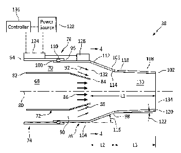
exhaust nozzle assembly.
The ejector nozzle converges in a direction from the first axial end to the
second axial end. The
ejector nozzle forms a mixing cross-sectional area between the primary nozzle
and the ejector
nozzle at the downstream axial end. The actuator is mounted on the ejector
nozzle. The actuator
is configured to axially move the ejector nozzle between a first axial
position and a second axial
position, relative to the outer shroud, to control an area of the mixing cross-
sectional area. The
mixing cross-sectional area has a first area with the ejector nozzle in the
first axial position and a
second area with the ejector nozzle in the second axial position. The first
area is greater than the
second area.
1
Date Recue/Date Received 2023-09-20
[0005] In any of the aspects or embodiments described above and herein, the
ejector nozzle may
include a first converging portion and a second converging portion. The first
converging portion
may have a first convergence angle relative to the exhaust centerline. The
second converging
portion may extend axially between and to the first converging portion and the
second axial end.
The second converging portion may have a second convergence angle relative to
the exhaust
centerline. The second convergence angle may be different than the first
convergence angle.
[0006] In any of the aspects or embodiments described above and herein, the
first converging
portion may form the mixing cross-sectional area with the ejector nozzle in
the first axial position.
[0007] In any of the aspects or embodiments described above and herein, the
second converging
portion may form the mixing cross-sectional area with the ejector nozzle in
the second axial
position.
[0008] In any of the aspects or embodiments described above and herein, the
ejector nozzle may
further include a sleeve portion extending between and to the first axial end
and the first
converging portion. The sleeve portion may be configured to slidingly contact
the outer shroud
as the ejector nozzle axially translates between the first axial position and
the second axial
position.
[0009] In any of the aspects or embodiments described above and herein, the
second
convergence angle may be less than the first convergence angle.
[0010] In any of the aspects or embodiments described above and herein, the
first converging
portion may have a first axial length and the second converging portion may
have a second axial
length. The second axial length may be greater than the first axial length.
[0011] In any of the aspects or embodiments described above and herein, the
actuator may
additionally be mounted on the outer shroud.
[0012] In any of the aspects or embodiments described above and herein, the
exhaust nozzle
assembly may further include a controller. The controller may include a
processor in
communication with a non-transitory memory storing instructions, which
instructions when
executed by the processor, may cause the processor to control the actuator to
axially move the
ejector nozzle.
2
Date Recue/Date Received 2023-09-20
[0013] In any of the aspects or embodiments described above and herein, the
instructions, when
executed by the processor, may further cause the processor to control the
actuator based on a
measured temperature of the propulsion system.
[0014] According to another aspect of the present disclosure, a propulsion
system includes a gas
turbine engine, a nacelle, and an exhaust nozzle assembly. The gas turbine
engine extends
along an axial centerline of the propulsion system. The gas turbine engine
includes a core
flowpath. The nacelle houses the gas turbine engine. The nacelle forms a
nacelle cavity between
the gas turbine engine and the nacelle. The nacelle cavity forms a secondary
flowpath. The
exhaust nozzle assembly including a primary nozzle, an outer shroud, and an
ejector nozzle. The
primary nozzle includes a downstream axial end. The primary nozzle forms the
core flowpath.
The outer shroud surrounds the primary nozzle. The outer shroud forms a
secondary annulus
between the primary nozzle and the outer shroud. The secondary flowpath
includes the
secondary annulus. The ejector nozzle is mounted to the outer shroud. The
ejector nozzle
extends between and to a first axial end and a second axial end. The ejector
nozzle forms a
mixing cross-sectional area between the primary nozzle and the ejector nozzle
at the downstream
axial end. The ejector nozzle further forms a mixing region extending axially
from the mixing
cross-sectional area to the second axial end. The mixing region is in fluid
communication with
the core flowpath and the secondary flowpath. The ejector nozzle is configured
to axially move
relative to the outer shroud to vary an area of the mixing cross-sectional
area and an axial length
of the mixing region.
[0015] In any of the aspects or embodiments described above and herein, the
ejector nozzle may
include a first converging portion and a second converging portion. The first
converging portion
may have a first convergence angle relative to the axial centerline. The
second converging portion
may extend axially between and to the first converging portion and the second
axial end. The
second converging portion may have a second convergence angle relative to the
axial centerline.
The second convergence angle may be different than the first convergence
angle.
[0016] In any of the aspects or embodiments described above and herein, the
second
convergence angle may be less than the first convergence angle.
[0017] In any of the aspects or embodiments described above and herein, the
first converging
portion may have a first axial length and the second converging portion may
have a second axial
length. The second axial length may be greater than the first axial length.
3
Date Recue/Date Received 2023-09-20
[0018] In any of the aspects or embodiments described above and herein, the
ejector nozzle may
be positionable in an axially forward position and an axially aft position.
The mixing cross-
sectional area may have a first area with the ejector nozzle in the axially
forward position and a
second area with the ejector nozzle in the axially aft position. The second
area may be greater
than the first area.
[0019] In any of the aspects or embodiments described above and herein, the
exhaust nozzle
assembly may further include an actuator mounted on the ejector nozzle. The
actuator may be
configured to axially move the ejector nozzle between a forward axial position
and an aft axial
position to control the area of the mixing cross-sectional area.
[0020] According to another aspect of the present disclosure, an exhaust
nozzle assembly for a
propulsion system includes a primary nozzle, an ejector nozzle, and an
actuator. The primary
nozzle extends along an exhaust centerline of the exhaust nozzle assembly. The
primary nozzle
includes a downstream axial end. The ejector nozzle extends axially between
first axial end and
second axial end. The second axially end is disposed downstream of the first
axial end. The
second axial end forms a nozzle exit plane for the exhaust nozzle assembly.
The ejector nozzle
forms a mixing cross-sectional area between the primary nozzle and the ejector
nozzle at the
downstream axial end. The actuator is mounted on the ejector nozzle. The
actuator is configured
to axially move the ejector nozzle between a forward axial position and an aft
axial position,
relative to the primary nozzle, to control an area of the mixing cross-
sectional area. The mixing
cross-sectional area has a first area with the ejector nozzle in the forward
axial position and a
second area with the ejector nozzle in the aft axial position. The second area
is greater than the
first area.
[0021] In any of the aspects or embodiments described above and herein, the
ejector nozzle may
converge in a direction from the first axial end to the second axial end.
[0022] In any of the aspects or embodiments described above and herein, the
ejector nozzle may
include a first converging portion and a second converging portion. The first
converging portion
may have a first convergence angle relative to the exhaust centerline. The
second converging
portion may extend axially between and to the first converging portion and the
second axial end.
The second converging portion may have a second convergence angle relative to
the exhaust
centerline. The second convergence angle may be different than the first
convergence angle.
4
Date Recue/Date Received 2023-09-20
[0023] In any of the aspects or embodiments described above and herein, the
first converging
portion may form the mixing cross-sectional area with the ejector nozzle in
the aft axial position
and the second converging portion may form the mixing cross-sectional area
with the ejector
nozzle in the forward axial position.
[0024] The present disclosure, and all its aspects, embodiments and advantages
associated
therewith will become more readily apparent in view of the detailed
description provided below,
including the accompanying drawings.
DESCRIPTION OF THE DRAVVINGS
[0025] FIG. 1 illustrates a perspective view of a perspective view of a
propulsion system for an
aircraft, in accordance with one or more embodiments of the present
disclosure.
[0026] FIG. 2 illustrates a schematic view of the propulsion system of FIG. 1,
in accordance with
one or more embodiments of the present disclosure.
[0027] FIG. 3 illustrates a side, cutaway view of an exhaust nozzle assembly,
in accordance with
one or more embodiments of the present disclosure.
[0028] FIG. 4 illustrates a cross-sectional view of the exhaust nozzle
assembly of FIG. 3 taken
along Line 4-4 of FIG. 3, in accordance with one or more embodiments of the
present disclosure.
[0029] FIG. 5 illustrates a side, cutaway view of an exhaust nozzle assembly,
in accordance with
one or more embodiments of the present disclosure.
[0030] FIG. 6 illustrates a cross-sectional view of the exhaust nozzle
assembly of FIG. 5 taken
along Line 6-6 of FIG. 5, in accordance with one or more embodiments of the
present disclosure.
DETAILED DESCRIPTION
[0031] FIGS. 1 and 2 illustrate a propulsion system 10 for an aircraft 1000.
The aircraft propulsion
system 10 includes a gas turbine engine 20 and a nacelle 22 (e.g., aircraft
propulsion system
housing). The propulsion system 10 (e.g., the nacelle 22) may be mounted to or
otherwise formed
by a portion of the aircraft 1000 such as, but not limited to, a wing or
fuselage of the aircraft 1000.
[0032] The gas turbine engine 20 of FIGS. 1 and 2 is configured as a turboprop
engine. However,
the present disclosure is not limited to any particular configuration of gas
turbine engine for the
Date Recue/Date Received 2023-09-20
propulsion assembly 10, and examples of gas turbine engine configurations for
the propulsion
system 10 may include, but are not limited to, a turbofan engine, a turbojet
engine, a propfan
engine, or the like. The gas turbine engine 20 of FIG. 2, for example,
includes an air inlet section
24, a compressor section 26, a combustor section 28, a turbine section 30, an
exhaust section
32, and an engine static structure 34. The compressor section 26 may include a
low-pressure
compressor (LPC) section 26A and a high-pressure compressor (HPC) section 26B.
The
combustor section 28 includes a combustor 36. The turbine section 30 may
include a low-
pressure turbine (LPT) section 30A and a high-pressure turbine (HPT) section
30B. The exhaust
section 32 and components thereof may be formed by portions of the nacelle 22
as well as the
gas turbine engine 20. The exhaust section 32 includes an exhaust nozzle
assembly 38.
[0033] The gas turbine engine 20 sections 26, 28, 30, and 32 of FIG. 2 are
arranged sequentially
along an axial centerline 40 (e.g., a rotational axis) of the propulsion
system 10 within the engine
static structure 34. The engine static structure 34 may include, for example,
one or more engine
cases 42. The engine static structure 34 may additionally include cowlings,
bearing assemblies,
or other structural components of the gas turbine engine. The one or more
engine cases 42
house and/or structurally support one or more of the engine sections 24, 26,
28, 30, and 32. The
engine sections 26, 28, 30, and 32 may be collectively referred to as an
"engine core."
[0034] The gas turbine engine 20 of FIG. 2 includes a first rotational
assembly 46 (e.g., a high-
pressure spool) and a second rotational assembly 48 (e.g., a low-pressure
spool). The first
rotational assembly 46 and the second rotational assembly 48 are mounted for
rotation about the
axial centerline 40 relative to the engine static structure 34.
[0035] The first rotational assembly 46 includes a first shaft 50, a bladed
first compressor rotor
52, and a bladed first turbine rotor 54. The first shaft 50 interconnects the
bladed first compressor
rotor 52 and the bladed first turbine rotor 54. The second rotational assembly
48 includes a
second shaft 56, a bladed second compressor rotor 58, a bladed second turbine
rotor 60, and a
propeller 62. The second shaft 56 interconnects the bladed second compressor
rotor 58 and the
bladed second turbine rotor 60. The second shaft 56 may directly interconnect
the propeller 62
with the bladed second compressor rotor 58 and the bladed second turbine rotor
60. Alternatively,
the second shaft 56 may be connected to the propeller 62, for example, by one
or more speed-
reducing gear assemblies (not shown) to drive the propeller 62 at a reduced
rotational speed
relative to the second shaft 56. The combustor 36 of FIG. 2 is disposed
between the bladed first
compressor rotor 52 and the bladed first turbine rotor 54 along the axial
centerline 40.
6
Date Recue/Date Received 2023-09-20
[0036] The nacelle 22 houses the gas turbine engine 20 and forms and
aerodynamic cover for
the propulsion system 10. For example, an outer skin 44 of the nacelle 22 of
FIG. 2 forms an
aerodynamic exterior of the propulsion system 10. The nacelle 22 of FIG. 2
extends
circumferentially about (e.g., completely around) the axial centerline 40. The
outer skin 44 may
be radially spaced from the gas turbine engine 20 to form a nacelle cavity 64
within the propulsion
system 10 between the outer skin 44 and the gas turbine engine 20. The nacelle
22 may house
or otherwise contain one or more auxiliary systems 200 of the propulsion
system 10 such as, but
not limited to electronic systems, electrical systems, hydraulic systems,
pneumatic systems,
sensors, and the like, which auxiliary systems 200 may be configured to
control or monitor various
operations of the propulsion system 10 or its gas turbine engine 20. The
nacelle 22 (e.g., the
outer skin 44) may include one or more openings configured to allow ambient
air to enter the
nacelle 22 and/or the nacelle cavity 64. The nacelle 22 of FIG. 2, for
example, includes a plurality
of louvers 66 extending through the outer skin 44. The louvers 66 are disposed
at (e.g., on,
adjacent, or proximate) an upstream end of the nacelle 22.
[0037] During operation of the propulsion system 10 of FIG. 2, air enters the
propulsion system
through the air inlet section 24 and is directed into a core flowpath 68. The
core flowpath 68
extends axially through the gas turbine engine 20 sections 26, 28, 30, and 32
of FIG. 2 to the
exhaust nozzle assembly 38. The air within the core flowpath 68 may be
referred to as "core air."
The core air is compressed by the bladed second compressor rotor 58 and the
bladed first
compressor rotor 52 and directed into a combustion chamber of the combustor
36. Fuel is injected
into the combustion chamber and mixed with the compressed core air to provide
a fuel-air mixture.
This fuel-air mixture is ignited and combustion products thereof flow through
and sequentially
cause the bladed first turbine rotor 54 and the bladed second turbine rotor 60
to rotate. The
rotation of the bladed first turbine rotor 54 and the bladed second turbine
rotor 60 respectively
drive rotation of the first rotational assembly 46 and the second rotational
assembly 48. The
combusted fuel-air mixture flows from the bladed second turbine rotor 54 along
the core flowpath
68 to the exhaust section 32 (e.g., the exhaust nozzle assembly 38). The
combusted fuel-air
mixture which enters exhaust section 32 may be referred to as "combustion
exhaust gas." During
operation of the propulsion system 10 of FIG. 2, air also enters the louvers
66 and is directed into
a secondary flowpath 70. The secondary flowpath 70 extends through the nacelle
22 and/or the
nacelle cavity 64 to the exhaust nozzle assembly 38. Air flow along the
secondary flowpath 70
may be used to provide cooling to the nacelle 22, the auxiliary systems 200,
and/or other systems
or components of the propulsion system 10. The air within the secondary
flowpath 70 may be
7
Date Recue/Date Received 2023-09-20
referred to as "secondary air." The aircraft propulsion system 10 of the
present disclosure,
however, is not limited to the exemplary gas turbine engine configuration
described above and
illustrated in FIG. 2.
[0038] FIGS. 3-6 illustrate portions of the exhaust nozzle assembly 38. The
exhaust nozzle
assembly includes a primary nozzle 72, an outer shroud 74, an ejector nozzle
76, and an actuator
78.
[0039] The primary nozzle 72 extends circumferentially about (e.g., completely
around) an axial
centerline 80 of the exhaust nozzle assembly 38 of FIGS. 3-6. The axial
centerline 80 may be
the same as or different than the axial centerline 40 for the propulsion
system 10. The primary
nozzle 72 extends (e.g., axially extends) between and to a first axial end 82
(e.g., an upstream
end) of the primary nozzle 72 and a second axial end 84 (e.g., a downstream
end) of the primary
nozzle 72, which second axial end 84 is axially downstream of the first axial
end 82. The primary
nozzle 72 may be mounted to the engine static structure 34 at (e.g., on,
adjacent, or proximate)
the first axial end 84 (see FIG. 2). For example, the first axial end 84 may
be mounted an engine
case (e.g., a turbine exhaust case (TEC) of the one or more engine cases 42
(see FIG. 2). The
primary nozzle 72 is configured to direct the combustion exhaust gas
(illustrated schematically as
combustion exhaust gas 86 in FIGS. 3 and 5) from the turbine section 30
through the primary
nozzle 72 toward the downstream ejector nozzle 76. The primary nozzle 72 may
include a mixer
88 at (e.g., on, adjacent, or proximate) the second axial end 84. The mixer 88
may be configured,
for example, as a forced mixer, a confluent mixer, or the like, however, the
present disclosure is
not limited to any particular configuration for the mixer 88. The mixer 88 may
be configured to
facilitate mixing of the combustion exhaust gas 86 with the secondary air in
the exhaust nozzle
assembly 38.
[0040] The outer shroud 74 extends circumferentially about (e.g., completely
around) the axial
centerline 80. The outer shroud 74 circumscribes the primary nozzle 72. The
outer shroud 74 is
radially spaced from the primary nozzle 72 to form a secondary annulus 90
radially between the
primary nozzle 72 and the outer shroud 74. Secondary air (schematically
illustrated as secondary
air 92 in FIGS. 3 and 5) may flow from the nacelle 22 and/or the nacelle
cavity 64 (see FIG. 2)
and through the secondary annulus 90 toward the downstream ejector nozzle 76.
The outer
shroud 74 may extend (e.g., axially extend) between and to a first axial end
94 of the outer shroud
74 and a second axial end 96 of the outer shroud 76, which second axial end 96
is axially
downstream of the first axial end 94. The second axial end 96 may be
positioned axially upstream
8
Date Recue/Date Received 2023-09-20
of the second axial end 84. The outer shroud 74 may be formed by, mounted to,
or otherwise in
contact with the nacelle 22.
[0041] The ejector nozzle 76 includes a nozzle body 98. The nozzle body 98
extends
circumferentially about (e.g., completely around) the axial centerline 80. The
nozzle body 98 is
radially spaced from the primary nozzle 72 to further form the secondary
annulus 90 radially
between the primary nozzle 72 and the ejector nozzle 76. The nozzle body 98
extends (e.g.,
axially extends) between and to a first axial end 100 (e.g., an upstream end)
of the ejector nozzle
76 and a second axial end 102 (e.g., a downstream end) of the ejector nozzle
76, which second
axial end 102 is axially downstream of the first axial end 100. The nozzle
body 98 forms and
surrounds a mixing region 130 of the ejector nozzle 76. The mixing region 130
is in fluid
communication with the core flowpath 68 and the secondary flowpath 70. The
mixing region 130
extends axially between the second axial end 84 and the second axial end 102.
The primary
nozzle 72 and the nozzle body 98 form a mixing cross-sectional area 132 of the
mixing region
130 at the second axial end 84. The mixing cross-sectional area 132 may be
understood, for
example, as an area between the primary nozzle 72 and the nozzle body 98 along
a radial plane
located at the second axial end 84. The second axial end 102 forms an exit
plane 134 for the
exhaust nozzle assembly 38. The mixing region 130 has an axial length L1
extending axially
between and to the mixing cross-sectional area 132 and the exit plane 134.
[0042] The nozzle body 98 of FIGS. 3 and 5 includes a sleeve portion 104, a
first convergent
portion 106, and a second convergent portion 108. Each of the sleeve portion
104, the first
convergent portion 106, and the second convergent portion 108 are axial
portions of the nozzle
body 98, which axial portions extend circumferentially about (e.g., completely
around) the axial
centerline 80. The sleeve portion 104 of FIGS. 3 and 5 extends (e.g., axially
extends) from the
first axial end 100 to the first convergent portion 106. The first convergent
portion 106 of FIGS. 3
and 5 extends (e.g., axially extends) from the sleeve portion 104 to the
second convergent portion
108. The second convergent portion 108 of FIGS. 3 and 5 extends (e.g., axially
extends) from
the first convergent portion 106 to the second axial end 102. As will be
discussed in further detail,
any of the sleeve portion 104, the first convergent portion 106, and the
second convergent portion
108 may form the mixing cross-sectional area 132 with the primary nozzle 72,
depending on an
axial position of the nozzle body 98 relative to the primary nozzle 72.
[0043] The sleeve portion 104 is positioned in sliding contact with the outer
shroud 74. For
example, the sleeve portion 104 of FIGS. 3 and 5 is configured to slide
axially along the outer
9
Date Recue/Date Received 2023-09-20
shroud 74 at (e.g., on, adjacent, or proximate) an interior surface of the
outer shroud 74.
Alternatively, the sleeve portion 104 may be configured to slide axially along
the outer shroud 74
at (e.g., on, adjacent, or proximate) an exterior surface of the outer shroud
74. The sleeve portion
104 may have a cylindrical shape which extends (e.g., axially extends) from
the first axial end 100
to the first convergent portion 106. The sleeve portion 104 may include a seal
110. The seal 110
may extend circumferentially about (e.g., completely around) the axial
centerline 80 on the sleeve
portion 104. The seal 110 may be in sliding contact with the outer shroud 74
to provide an annular
fluid seal between the outer shroud and the sleeve portion 104.
[0044] The first converging portion 106 of FIGS. 3 and 5 converges radially
inward in a first
convergence direction from an upstream end 112 of the first converging portion
106 to a
downstream end 114 of the first converging portion 106. For example, the
upstream end 112 of
FIGS. 3 and 5 is disposed radially outward of the downstream end 114. The
first convergence
direction may be defined by an average position of the first converging
portion 106 from the
upstream end 112 to the downstream end 114. The first converging portion 106
(e.g., the first
convergence direction) is disposed at a convergence angle 116 relative to the
axial centerline 80.
The first converging portion 106 has an axial length L2 extending (e.g.,
axially extending) from
the upstream end 112 to the downstream end 114.
[0045] The second converging portion 108 of FIGS. 3 and 5 converges radially
inward in a second
convergence direction from an upstream end 118 of the second converging
portion 108 to a
downstream end 120 of the second converging portion 108. For example, the
upstream end 118
of FIGS. 3 and 5 is disposed radially outward of the downstream end 120. The
second
convergence direction may be defined by an average position of the second
converging portion
108 from the upstream end 118 to the downstream end 120. The second converging
portion 108
(e.g., the second convergence direction) is disposed at a convergence angle
122 relative to the
axial centerline 80. The convergence angle 122 of FIGS. 3 and 5 is less than
the convergence
angle 116 of FIGS. 3 and 5. The second converging portion 108 has an axial
length L3 extending
(e.g., axially extending) from the upstream end 118 to the downstream end 120.
The axial length
L3 of FIGS. 3 and 5 is greater than the axial length L2.
[0046] During operation of the propulsion system 10 (see FIG. 2), the
combustion exhaust gas
86 flow into and through the mixing region 130 mixes with the secondary air 92
flowing from the
secondary annulus 90 into the mixing region 130 (e.g., by shear fluid friction
forces). The
secondary air 92 is mixed (e.g., entrained) with the relatively higher
velocity combustion exhaust
Date Recue/Date Received 2023-09-20
gas 86. Mixing of the secondary air 92 with the combustion exhaust gas 86
increases a flow rate
of the secondary air through the nacelle 22 and/or the nacelle cavity 66,
thereby increasing the
secondary air cooling provided to the nacelle 22 as well as auxiliary systems
200 of the propulsion
system 10 contained within the nacelle 22 (see FIG. 2).
[0047] The actuator 78 of FIGS. 3 and 5 includes a first actuator member 124,
a second actuator
member 126, and a power source 128. The first actuator member 124 is mounted
to outer shroud
74 (e.g., on an exterior of the outer shroud 74) or another fixed portion of
the nacelle 22 (see FIG.
2). The second actuator member 126 is mounted to the ejector nozzle 76. For
example, the
second actuator member 126 of FIGS. 3 and 5 is mounted on an exterior of the
sleeve portion
104. The present disclosure, however, is not limited to the particular
configuration of the first
actuator member 124 and the second actuator member 126 of FIGS. 3 and 5. The
actuator 78
may be configured as a linear actuator in which the actuator 78 is configured
to effect axial
movement (e.g., linear axial translation) of the second actuator member 126
relative to the first
actuator member 124. The actuator 78 may be configured as a hydraulic
actuator, a pneumatic
actuator, an electro-mechanical actuator, a rack-and-pinion actuator, or the
like, which may be
configured to effect axial movement of the second actuator member 126 relative
to the first
actuator member 124. The power source 128 may be any power source, such as an
electrical
power source (e.g., a battery and/or a generator), a hydraulic power source,
or a pneumatic power
source (e.g., compressor bleed air), configured to facilitate axial movement
of the second actuator
member 126 relative to the first actuator member 124. The present disclosure,
however, is not
limited to the particular actuator 78 configuration illustrated in FIGS. 3and
5.
[0048] The actuator 78 is configured to effect axial movement of the ejector
nozzle 76 to control
an axial position of the ejector nozzle 76 relative to the primary nozzle 72
and the outer shroud
74 and, therefore, to control (e.g., selectively vary) an area of the mixing
cross-sectional area 132.
By controlling the area of the mixing cross-sectional area 132, a flow rate of
the secondary air 92
through the nacelle 22 and/or the nacelle cavity 66 (see FIG. 2) may also be
controlled, thereby
facilitating modulation of the secondary air 92 flow to provide sufficient
secondary air cooling to
the nacelle 22 and auxiliary systems 200 of the propulsion system 10 contained
within the nacelle
22 (see FIG. 2) while also limiting thrust losses and aerodynamic drag for the
propulsion system
10. For example, FIGS. 3 and 4 illustrate the ejector nozzle 76 in a first
axial position (e.g., an aft
position) relative to the primary nozzle 72 and FIGS. 5 and 6 illustrate the
ejector nozzle 76 in a
different second axial position (e.g., a forward position) relative to the
primary nozzle 72. The
area of the mixing cross-sectional area 132 of FIGS. 3 and 4 is greater than
the area of the mixing
11
Date Recue/Date Received 2023-09-20
cross-sectional area 132 of FIGS. 5 and 6. A greater area of the mixing cross-
sectional area 132
may correspond with an increase in the flow rate of secondary air 92 through
the nacelle 22 and/or
the nacelle cavity 66 and into the exhaust nozzle assembly 38. The first axial
position of the
ejector nozzle 76 in FIGS. 3 and 4 is an axially extended position (e.g., in
an axially downstream
direction) of the ejector nozzle 76 relative to the second axial position of
the ejector nozzle 76 in
FIGS. 5 and 6.
[0049] As a result of the converging configuration of the first converging
portion 106 and the
second converging portion 108, axial movement of the ejector nozzle 76
relative to the primary
nozzle 72 may cause the area of the mixing cross-sectional area 132 to vary.
Axial movement of
the ejector nozzle 76 in an axially downstream direction may cause an increase
in the area of the
mixing cross-sectional area 132, as well as an increase in the axial length L1
and volume of the
mixing region 130. Axial movement of the ejector nozzle 76 in an axially
upstream direction may
cause a decrease in the area of the mixing cross-sectional area 132, as well
as a decrease in the
axial length L1 and volume of the mixing region 130. The lesser convergence
angle 122 and
greater axial length L3 of the second converging portion 108 relative to the
convergence angle
116 and axial length L2 of the first converging portion 106 may facilitate
greater reductions the
area of the mixing cross-sectional area 132 while also facilitating a
sufficient axial length L1 of the
mixing region 130 for more complete mixing of the combustion exhaust gas 86
with the secondary
air 92.
[0050] Referring to FIGS. 2, 3, and 5, in some embodiments, the propulsion
system 10 may
include a controller 136 configured to control operation of the actuator 78
for selectively
positioning the ejector nozzle 76. The controller 136 of FIG. 2 includes a
processor 138 and
memory 140. The memory 140 is in signal communication with the processor 138.
The processor
138 may include any type of computing device, computational circuit, or any
type of process or
processing circuit capable of executing a series of instructions that are
stored in the memory 140,
thereby causing the processor 138 to perform or control one or more steps or
other processes.
The processor 138 may include multiple processors and/or multicore CPUs and
may include any
type of processor, such as a microprocessor, digital signal processor, co-
processors, a micro-
controller, a microcomputer, a central processing unit, a field programmable
gate array, a
programmable logic device, a state machine, logic circuitry, analog circuitry,
digital circuitry, etc.,
and any combination thereof. The instructions stored in mem0ry140 may
represent one or more
algorithms for controlling the aspects of the propulsion system 10, and the
stored instructions are
not limited to any particular form (e.g., program files, system data, buffers,
drivers, utilities, system
12
Date Recue/Date Received 2023-09-20
programs, etc.) provided they can be executed by the processor 138. The memory
140 may be
a non-transitory computer readable storage medium configured to store
instructions that when
executed by one or more processors, cause the one or more processors to
perform or cause the
performance of certain functions. The memory 140 may be a single memory device
or a plurality
of memory devices. A memory device may include a storage area network, network
attached
storage, as well a disk drive, a read-only memory, random access memory,
volatile memory, non-
volatile memory, static memory, dynamic memory, flash memory, cache memory,
and/or any
device that stores digital information. One skilled in the art will
appreciate, based on a review of
this disclosure, that the implementation of the controller 136 may be achieved
via the use of
hardware, software, firmware, or any combination thereof. The controller 136
may also include
input and output devices (e.g., keyboards, buttons, switches, touch screens,
video monitors,
sensor readouts, data ports, etc.) that enable the operator to input
instructions, receive data, etc.
[0051] The controller 136 may form or otherwise be part of an electronic
engine controller (EEC)
for the propulsion system 10. The EEC may control operating parameters of the
gas turbine
engine 20 including, but not limited to, fuel flow, stator vane position,
compressor air bleed valve
position, etc. so as to control an engine power and/or thrust of the gas
turbine engine 20. In some
embodiments, the EEC may be part of a full authority digital engine control
(FADEC) system for
the gas turbine engine 20.
[0052] The controller 136 may be in communication (e.g., signal communication)
with one or
more sensors of the propulsion system 10. For example, the controller 136 may
be in signal
communication with one or more temperature sensors 142 disposed on or within
the nacelle 22.
The temperature sensors 142 may be configured to measure temperatures of the
nacelle 22
and/or one or more auxiliary systems 200 of the propulsion system 10 housed
within the nacelle
22. The temperature sensors 142 may additionally or alternatively be
configured to measure
temperatures of the secondary air 92 within the nacelle 22, the nacelle cavity
66, and/or the
exhaust nozzle assembly 38. The memory 140 may include instructions which,
when executed
by the processor 138, cause the controller 136 and/or its processor 138 to
control a position of
the ejector nozzle 76 (e.g., with the actuator 78) to control a temperature of
the nacelle 22 and/or
auxiliary systems 200 (hereinafter a "nacelle temperature"), as measured by
the temperature
sensors 142. For example, the controller 136 may be configured to control a
position of the ejector
nozzle 76 and, hence, an area of the mixing cross-sectional area 130, to
maintain the nacelle
temperature within a predetermined temperature range. The controller 136 may
be configured to
identify that a high-temperature condition is present or absent based on a
first predetermined
13
Date Recue/Date Received 2023-09-20
threshold value of the nacelle temperature. The controller 136 may be
configured to increase an
area of the mixing cross-sectional area 132 in response to the nacelle
temperature (e.g.,
measured by the temperature sensor(s) 142) increasing to or above the first
predetermined
threshold value, thereby increasing the flow rate of secondary air 92 through
the nacelle 22 and/or
the nacelle cavity 66. The controller 136 may be configured to identify that a
low-temperature
condition is present or absent based on a second predetermined threshold value
of the nacelle
temperature. The controller 136 may be configured to decrease an area of the
mixing cross-
sectional area 132 in response to the nacelle temperature (e.g., measured by
the temperature
sensor(s) 142) decreasing to or below the second predetermined threshold
value, thereby
improving performance and/or efficiency of the gas turbine engine 20.
[0053] It is noted that various connections are set forth between elements in
the preceding
description and in the drawings. It is noted that these connections are
general and, unless
specified otherwise, may be direct or indirect and that this specification is
not intended to be
limiting in this respect. A coupling between two or more entities may refer to
a direct connection
or an indirect connection. An indirect connection may incorporate one or more
intervening
entities.
[0054] Furthermore, no element, component, or method step in the present
disclosure is intended
to be dedicated to the public regardless of whether the element, component, or
method step is
explicitly recited in the claims. No claim element herein is to be construed
under the provisions
of 35 U.S.C. 112(f) unless the element is expressly recited using the phrase
"means for." As used
herein, the terms "comprises", "comprising", or any other variation thereof,
are intended to cover
a non-exclusive inclusion, such that a process, method, article, or apparatus
that comprises a list
of elements does not include only those elements but may include other
elements not expressly
listed or inherent to such process, method, article, or apparatus.
[0055] While various aspects of the present disclosure have been disclosed, it
will be apparent
to those of ordinary skill in the art that many more embodiments and
implementations are possible
within the scope of the present disclosure. For example, the present
disclosure as described
herein includes several aspects and embodiments that include particular
features. Although these
particular features may be described individually, it is within the scope of
the present disclosure
that some or all of these features may be combined with any one of the aspects
and remain within
the scope of the present disclosure. References to "various embodiments," "one
embodiment,"
"an embodiment," "an example embodiment," etc., indicate that the embodiment
described may
14
Date Recue/Date Received 2023-09-20
include a particular feature, structure, or characteristic, but every
embodiment may not
necessarily include the particular feature, structure, or characteristic.
Moreover, such phrases
are not necessarily referring to the same embodiment. Further, when a
particular feature,
structure, or characteristic is described in connection with an embodiment, it
is submitted that it
is within the knowledge of one skilled in the art to effect such feature,
structure, or characteristic
in connection with other embodiments whether or not explicitly described.
Accordingly, the
present disclosure is not to be restricted except in light of the attached
claims and their
equivalents.
Date Recue/Date Received 2023-09-20