Note : Les descriptions sont présentées dans la langue officielle dans laquelle elles ont été soumises.
WO 2022/248206
PCT/EP2022/062547
1
TITLE
A split-deck screening device for screening bulk material
Field of the Invention
The present invention relates to a a split-deck screening device for screening
bulk
material. Also described is a screening plant assembly in a static or mobile
form
that includes a split-deck.
Background to the Invention
Various types of screening devices for bulk material have been developed for
screening or sorting bulk materials such as quarry stone, site clearance
materials,
domestic and industrial waste. They generally include a screening deck with
holes
defining a mesh size and a vibrational apparatus to vibrate the deck to screen
the
material delivered on to the deck, and an arrangement of conveyors to collect
screened material that has passed through the deck and unscreened material
that
has not passed through the deck. Often the device will include more than one
screening deck arranged in a stacked arrangement, with each deck having a
different mesh size, and an arrangement of conveyors to collect material from
the
respective decks are deliver the screened materials to different stockpiles.
Generally, the screening deck(s) are mounted in a screen box configured to
vibrate
to assist with screening of the material and to move the material along the
deck
from a loading end to a discharge end. The deck may be inclined downwardly
from
a loading end to a discharge end to vary the residence time of the bulk
material on
the deck. For example, loose and easily separated bulk material requires a
shorted
residence time on the deck allowing the deck to tilted to increase the speed
on
movement of the material along the deck, whereas wet material require a longer
CA 03216310 2023- 10- 20
WO 2022/248206
PCT/EP2022/062547
2
time on the deck and may therefore be screened on a horizontal or near-
horizontal
deck.
In some devices, the screening deck(s) are split and provided as a primary
screen
box containing one or more decks and a secondary screen box containing one or
more decks, with a discharge end of the primary screen box adjacent to the
loading
end of the secondary screen box allowing the discharge ends of the deck or
decks
in the primary screen box delivery material on to a loading end of the
corresponding
decks in the secondary screen box. The splitting of the decks allows the angle
of
screening to be varied along the deck, and also allows the individual screen
boxes
to be operated higher speeds and amplitudes which equates to better
performance.
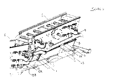
Figure 1 (prior art) shows a known split-deck screening device (A) having two
decks
for screening bulk material comprising a main sub-frame (B) mountable on a
main
frame (not shown), a primary screen box (C) comprising a plurality of
vertically
stacked screening decks (not shown) having a loading end (D1) to receive a
supply
of bulk material and an opposite discharge end (El) to discharge non-screened
material, a secondary screen box (F) mounted to the main sub-frame comprising
a
plurality of screening decks (not shown) having a loading end (D2) adjacent to
the
discharge end (El) of the primary screen box and an opposite discharge end
(E2)
to discharge unscreened material, a primary screen box sub-frame (F) coupled
to
the main sub-frame having a discharge end (G) and a loading end (H), and a
tilting
mechanism (I) to tilt the primary screen box sub-frame relative to the main
sub-
frame downwardly towards the secondary screen box. A problem with this type of
split-deck multi-deck device is that the primary and secondary screen boxes
are
mounted to the main sub-frame in a fixed position. Thus, if one of the lower
decks
of the secondary screen box requires maintenance (which is a common occurrence
for screening decks used to screen quarry bulk materials), it is necessary to
remove
the upper deck or decks in order to gain access to the lower deck, which is a
difficult and time-consuming operation. This problem is compounded by the fact
that screening plant machines are often located in remote locations and have
to be
CA 03216310 2023- 10- 20
WO 2022/248206
PCT/EP2022/062547
3
maintained on site which involves bringing specialist lifting equipment to the
machines themselves as opposed to bringing the machine to a repair location.
It is an objective of the invention to overcome at least one of the above-
referenced
problems.
Summary of the Invention
The objective is met by the provision of a split-deck screening device
according to
the preamble of Claim 1, in which the device includes a sub-frame carriage to
which
the primary box sub-frame is attached and in which the sub-frame carriage is
mounted to the main sub-frame and actable to move the primary box sub-frame up
and away from the secondary screen box. This results in the primary screen box
(and associated sub-frame) being moved from an operative position (shown in
Figure 2 or Figure 4 (tilted) to an inoperative position that is spaced
laterally and
vertically from the secondary box as shown in Figures 6 and 7. This movement
of
the primary screen box up and away from the secondary screen box permits
access to the front end of the secondary screen box allowing maintenance to be
performed, including removal of one or more of the lower decks in the
secondary
screen box as illustrated in Figure 13.
In a first aspect, the invention provides a split-deck screening device for
screening
bulk material comprising:
a main sub-frame mountable on a main frame;
a primary screen box comprising a plurality of screening decks having a
loading end to receive a supply of bulk material and an opposite discharge end
to
discharge non-screened material;
a secondary screen box mounted to the main sub-frame comprising a
plurality of screening decks having a loading end adjacent to the discharge
end of
the primary screen box and an opposite discharge end to discharge unscreened
material;
CA 03216310 2023- 10- 20
WO 2022/248206
PCT/EP2022/062547
4
a primary screen box sub-frame coupled to the main sub-frame having a
discharge end and a loading end, and
optionally, a tilting mechanism to tilt the primary screen box sub-frame
relative to the main sub-frame downwardly towards the secondary screen box,
characterized in that the split-deck screening device comprises:
a sub-frame carriage for coupling the primary screen box sub-frame to the
main sub-frame (generally attached at each side of the discharge end of the
primary screen box sub-frame) and actuable to move the primary screen box from
an operative position in which the discharge end of the primary screen box is
disposed adjacent to a receiving end of the secondary screen box to an
inoperative
position in which the primary screen box is laterally and vertically spaced
from the
secondary screen box to thereby provide access to one or more lower screening
decks in the secondary screen box; and
a first actuator to actuate the sub-frame carriage.
The device of the invention allows an efficient separation of the primary and
secondary screen boxes to allow access to a rear end of the secondary screen
box
(and the lower decks contained in the box).
In any embodiment, the sub-frame carriage is slidably mounted to the main sub-
frame for movement (typically angled movement) from the operative position to
the
inoperative position.
In any embodiment, the first actuator is coupled between the main sub-frame
and
each sub-frame carriage and operable to move the sub-frame carriages between
the operative position and the inoperative position.
The use of a slidable sub-frame carriage allows controlled movement of the sub-
frame carriage which is guided by the sliding relationship between the sub-
frame
carriage and the main sub-frame and driven by the actuator.
CA 03216310 2023- 10- 20
WO 2022/248206
PCT/EP2022/062547
In other embodiments, the sub-frame carriage may be pivotally or hingedly
mounted to the main sub-frame or coupled thereto by means of linkages.
In any embodiment, each sub-frame carriage is pivotally attached to the
primary
5 screen box sub-frame, and the device typically comprises a second
actuator
coupled between each sub-frame carriage and the primary screen box sub-frame
and operable to tilt the primary screen box sub-frame relative to the sub-
frame
carriage.
In any embodiment, each of the primary and secondary screen boxes comprise at
least two screening decks.
In any embodiment, each of the primary and secondary screen boxes comprise at
least three or four screening decks.
In any embodiment, each sub-frame carriage comprises a supporting leg and an
upper section disposed on top of the supporting leg, in which the main sub-
frame
comprises guide sections (generally disposed on each side of a discharge end
of
the main sub-frame) configured to receive each supporting leg in a sliding
manner
and guide the sliding movement of the sub-frame carriage between the operative
and inoperative positions.
In any embodiment, the supporting leg has a rectangular profile.
In any embodiment, the guide section of the main sub-frame has a rectangular
profile configured to receive the supporting leg.
In any embodiment, the guide section is dimensioned to receive the supporting
leg
in a tight but sliding relationship.
CA 03216310 2023- 10- 20
WO 2022/248206
PCT/EP2022/062547
6
In any embodiment, each guide section of the main sub-frame defines a linear
sliding path for the sub-frame carriage which is disposed at an angle 0 of
about 30
to about 600 to a longitudinal axis of the main sub-frame.
In any embodiment, each guide section of the main sub-frame defines a linear
sliding path for the sub-frame carriage which is disposed at an angle 0 of
about 35
to about 55 to a longitudinal axis of the main sub-frame.
In any embodiment, each guide section of the main sub-frame defines a linear
sliding path for the sub-frame carriage which is disposed at an angle 0 of
about 40
to about 50 to a longitudinal axis of the main sub-frame.
In any embodiment, the upper section of each sub-frame carriage has a front
section disposed above the supporting leg and a rear section, in which the
front
section is pivotally attached to the discharge end of the primary screen box
sub-
frame, and the rear section is attached to one end of each of the first and
second
actuators.
In any embodiment, the upper section of each sub-frame carriage comprises two
spaced-apart upwardly depending plates, and in which the discharge end of the
primary screen box sub-frame is pivotally mounted to the upper section between
the plates.
In any embodiment, the main sub-frame comprises a guide for the primary screen
box sub-frame disposed on each side of the primary screen box.
In any embodiment, the guide comprises two spaced apart plates configured to
receive and guide a section of the primary screen box sub-frame during
movement
between the operative and inoperative positions.
In any embodiment, the guide comprises supporting means for supporting the
primary box sub-frame in at least one position.
CA 03216310 2023- 10- 20
WO 2022/248206
PCT/EP2022/062547
7
In any embodiment, the spaced apart plates comprise a series of holes for
receipt
of a locking pin to lock the primary screen box sub-frame in one of a
plurality of
positions above the main sub-frame.
In any embodiment, the secondary screen box is adjustably movable towards the
primary screen box when the primary screen box is in the inoperative position.
In any embodiment, the secondary screen box comprises a length adjustable
torque element configured for mounting between the secondary screen box and
main sub-frame and actuable to move the secondary screen box towards the
primary screen box.
In any embodiment, the device comprises at least two length adjustable torque
element, configured for mounting to opposed sidewalls of the secondary screen
box.
In any embodiment, the first and second actuating means are each,
independently,
hydraulic or pneumatic rams or electrical actuators.
In another aspect, there is provided a screening plant assembly comprising a
main
frame, and a split deck screening device according to the inventio, mounted to
the
main frame.
The screening plant assembly may be a static screening plant assembly or a
mobile screening plant assembly.
In any embodiment, the screening device or screening plant assembly comprises
separate discharge conveyors arranged to discharge, to separate stockpiles,
screened material in different size ranges.
CA 03216310 2023- 10- 20
WO 2022/248206
PCT/EP2022/062547
8
In another aspect, the invention provides a method of maintaining a split-deck
screening device, comprising the steps of
actuating the first actuator to move the sub-frame carriage to the inoperative
position in which the primary screen box is spaced above and away from the
secondary screen box to thereby provide access to one or more lower screening
decks in the secondary screen box; and
accessing a rear of the secondary screen box or a front of the primary screen
box
to perform maintenance.
In any embodiment, the step of maintaining comprises removing one or more of
the
lower screening decks of the secondary screen box without having to remove an
upper screening deck of the secondary screen box.
In any embodiment, the split-deck screening device is a mobile or static split-
screen
screening device.
In any embodiment, the maintenance is performed in the field, for example at a
quarry.
Other aspects and preferred embodiments of the invention are defined and
described in the other claims set out below.
Brief Description of the Figures
FIG. 1 (prior art) illustrates a split-deck screening device for screening
bulk
material having two decks and incorporating a tilting mechanism for the
primary
screen box.
FIG.2 is a perspective view from the side of a split-deck screening device
according
to the invention shown in an operative position.
CA 03216310 2023- 10- 20
WO 2022/248206
PCT/EP2022/062547
9
FIG. 3 is a side elevational view of the split-deck screening device of Figure
2 in an
operative position.
FIG. 4 is a perspective view from the side of the split-deck screening device
of
Figure 1 showing the primary screen box and primary screen box sub-frame in an
operative and tilted position.
FIG. 5 is a side elevational view of the split-deck screening device in the
operative
and tilted position shown in Figure 4.
FIG. 6 is a perspective view from the side of the split-deck screening device
of
Figure 1 in an inoperative position showing the primary screen box and primary
screen box sub-frame laterally and vertically spaced from the secondary screen
box.
FIG. 7 is a side elevational view of the split-deck screening device in the
inoperative
and raised position shown in Figure 6.
FIG. 8 is a side elevational view of a sub-frame carriage forming part of the
split-
deck screening device of the invention.
FIG. 9A is a side elevational view of the sub-frame carriage of Figure with
first and
second actuation rams attached and the first actuation ram retracted
(operative
position).
FIG. 9B is a side elevational view of the sub-frame carriage of Figure 9A
showing
the first actuation ram extended (inoperative position).
FIG. 10 is a perspective view of the primary screen box sub-frame attached at
each
side to a sub-frame carriage and showing the first actuation ram attached to
the
sub-frame carriage in a retracted (operative) position. The second actuation
ram
CA 03216310 2023- 10- 20
WO 2022/248206
PCT/EP2022/062547
(hidden) is in retracted position which means that the primary screen box sub-
frame
is not tilted upwardly relative to the sub-frame carriage.
FIG. 11 is a perspective view similar to Figure 10 but in which the second
actuation
5 rams (hidden) have been actuated to tilt the primary screen box sub-frame
upwardly relative to the sub-frame carriage.
FIG. 12 is a perspective view similar to Figure 11 but in which the first
actuation
rams have been actuated to move the primary screen box sub-frame up and away
10 from the secondary screen box (not shown) while maintaining the angle of
tilt of the
primary screen box sub-frame.
FIG. 13 is a side elevational view (shown from an opposite side of the device
from
Figure 7) showing the primary screen box in the inoperative position and
showing
the removal of the lower screen decks from the secondary screen box to allow
maintenance.
Detailed Description of the Invention
All publications, patents, patent applications and other references mentioned
herein
are hereby incorporated by reference in their entireties for all purposes as
if each
individual publication, patent or patent application were specifically and
individually
indicated to be incorporated by reference and the content thereof recited in
full.
Where used herein and unless specifically indicated otherwise, the following
terms
are intended to have the following meanings in addition to any broader (or
narrower) meanings the terms might enjoy in the art:
Unless otherwise required by context, the use herein of the singular is to be
read to
include the plural and vice versa. The term "a" or "an" used in relation to an
entity
is to be read to refer to one or more of that entity. As such, the terms "a"
(or "an"),
"one or more," and "at least one" are used interchangeably herein.
CA 03216310 2023- 10- 20
WO 2022/248206
PCT/EP2022/062547
11
As used herein, the term "comprise," or variations thereof such as "comprises"
or
"comprising," are to be read to indicate the inclusion of any recited integer
(e.g. a
feature, element, characteristic, property, method/process step or limitation)
or
group of integers (e.g. features, element, characteristics, properties,
method/process steps or limitations) but not the exclusion of any other
integer or
group of integers. Thus, as used herein the term "comprising" is inclusive or
open-
ended and does not exclude additional, unrecited integers or method/process
steps.
As used herein, the phrase "the primary screen box is laterally and vertically
spaced from the secondary screen box" means that the primary screen box is
moved up and away from the secondary screen box from an operative position to
an inoperative position that allows access to the front of the secondary
screen box.
Generally, there is no movement of the secondary screen box in the Z-plane.
This
results in the primary screen box (and associated sub-frame) being moved from
an
operative position (shown in Figure 2 or Figure 4 (tilted) to an inoperative
position
that is spaced laterally and vertically from the secondary box as shown in
Figures 6
and 7.
Exemplification
The invention will now be described with reference to specific Examples. These
are merely exemplary and for illustrative purposes only: they are not intended
to be
limiting in any way to the scope of the monopoly claimed or to the invention
described. These examples constitute the best mode currently contemplated for
practicing the invention.
Referring to the drawings, and initially to Figure 1 (prior art), a known
split-deck
screening device (A) for screening bulk material is shown. The device
comprises a
main sub-frame (B) mountable on a main frame (not shown), a primary screen box
(C) comprising a plurality of vertically stacked screening decks (not shown)
having
a loading end (D1) to receive a supply of bulk material and an opposite
discharge
CA 03216310 2023- 10- 20
WO 2022/248206
PCT/EP2022/062547
12
end (El) to discharge non-screened material, a secondary screen box (F)
mounted
to the main sub-frame comprising a plurality of screening decks (not shown)
having
a loading end (02) adjacent to the discharge end (El) of the primary screen
box
and an opposite discharge end (E2) to discharge unscreened material, a primary
screen box sub-frame (G) coupled to the main sub-frame having a discharge end
(H) and a loading end (I), and a tilting mechanism (J) to tilt the primary
screen box
sub-frame relative to the main sub-frame downwardly towards the secondary
screen box.
Referring to Figures 2 to 7, the split-deck screening device of the invention
is
illustrated, and the maintenance of the screening device is illustrated in
Figure 8.
Referring to Figures 2 to 7, the splits-screen screening device of the
invention (1)
comprises a main sub-frame (2) mountable on a main frame (not shown), a
primary
screen box (3) comprising a plurality of screening decks (not shown) having a
loading end (4A) to receive a supply of bulk material and an opposite
discharge
(5A) end to discharge non-screened material, and a secondary screen box (6)
mounted to the main sub-frame (2) comprising a plurality of screening decks
(not
shown) having a loading end (4B) adjacent to the discharge end (5A) of the
primary
screen box and an opposite discharge end (not shown)) to discharge unscreened
material. The primary screen box (3) is mounted on a primary screen box sub-
frame (7) having a longitudinal side beams (8) connected by an end beam (9).
The primary and secondary screen boxes are substantially the same as those of
the prior art and include vertically stacked screening decks (generally three
or four)
and supporting struts for the screening decks, and vibrational mechanisms for
vibrating the screening decks to screen material and urge material along the
decks
from the loading end to the discharge end.
In the split-deck screening device of the invention, the primary box sub frame
(7) is
not directly attached to the main sub-frame (2) but is coupled thereto by
means of
two sub-frame carriages (10) disposed on each side of the device. Each sub-
frame
CA 03216310 2023- 10- 20
WO 2022/248206
PCT/EP2022/062547
13
carriage (10) is pivotally attached to the primary screen box sub-frame (7) by
a
pivot joint (11) at a discharge end of the sub-frame (7) and slidably mounted
to the
main sub-frame (2) for movement from an operative position in which the
discharge
end (5A) of the primary screen box (3) is disposed adjacent to a receiving end
of
the secondary screen box (See Figures 2-5) to an inoperative position in which
the
primary screen box (3) is spaced above and away from the secondary screen box
(6) to thereby provide access to one or more lower screening decks in the
secondary screen box (See Figures 6 and 7).
The main sub-frame (2) comprises a guide for the primary screen box sub-frame
disposed on each side of the primary screen box (3), the guide comprising two
triangular spaced apart plates (12A, 12B) configured to receive and guide a
section
of the primary screen box sub-frame during movement between the operative and
inoperative positions. The plates (12) include a series of corresponding holes
(13)
configured to receive mounting pins to support the primary screen box sub-
frame in
a raised position.
Referring specifically to Figure 8, the sub-frame carriage (10) is provided by
an
elongated element that is cranked intermediate it's ends to provide a
supporting leg
(14) having a rectangular profile and an upper section (15) that in this
embodiment
is disposed at an angle 0 of about 1350 to the supporting leg (14). The upper
section (15) comprises a rear end (18) defined by two spaced-apart plates
(16A,
16B) that in use receive an end of a longitudinal side beam (shown as 8 in
Figure
12) of the primary box sub-frame and has a front end (17) that in use is
pivotally
attached to an end of the longitudinal side beam (8).. Referring to Figure 6,
each
side of the main sub-frame includes a guiding sleeve (19) having a rectangular
profile configured to receive the supporting leg (14) in a tight but sliding
relationship. The guiding sleeve (19) is defined by a front wall (19A) and
side walls
(19B) and is disposed at an angle of about 45 to a longitudinal axis of the
main
sub-frame (2). It will be appreciated that different angles may be employed
depending on the type of type of primary screen box and the number of decks,
for
CA 03216310 2023- 10- 20
WO 2022/248206
PCT/EP2022/062547
14
example 20-600, although for a three or four screen deck an angle of about 40-
50
has been found to be ideal.
Referring to Figures 9 to 12, a first actuation means in the form of a
hydraulic ram
(20) is mounted between the main sub-frame (2) and rear end (18) of the upper
section of each sub-frame carriage (10) and is used to move the sub-frame
carriage
(and primary screen box sub-frame/primary screen box) from the operative
position
shown in Figures 2-5 to the inoperative position shown in Figures 6 and 7.
Figures
9A and 9B clearly illustrate the movement of the sub-frame carriage relative
to the
main sub-frame (not shown) when the actuation ram (20) is actuated. A second
actuation means in the form of a hydraulic ram (22) is mounted between the
primary screen box sub-frame (7) and the rear end (18) of the upper section of
each sub-frame carriage (10), and is operable to tilt the primary screen deck
is also
provided and coupled between each sub-frame carriage and the primary screen
box sub-frame and operable to tilt the primary screen box sub-frame relative
to the
sub-frame carriage.
Figures 10 to 12 illustrates the sub-frame carriages (10) attached to each
side the
primary screen box sub-frame (7) and the first actuation ram (20) the second
actuation ram (hidden) attached to the carriage (10). In Figure 11, the second
actuation rams (22) have been actuated to tilt the primary screen box sub-
frame (7)
upwardly relative to the sub-frame carriages (10). In Figure 12, the first
actuation
rams (20) have been actuated to move the carriage (10) up and away from the
main frame while maintaining the angle of the primary screen box sub-frame (7)
relative to the main frame.
Figure 13 illustrates the screening device of the invention in an inoperative
position
with the primary screen box (3) separated (moved up and away) from the
secondary screen box (6) and showing the lower screening decks (25) being
removed from the front end of the secondary screen box.
Equivalents
CA 03216310 2023- 10- 20
WO 2022/248206
PCT/EP2022/062547
The foregoing description details presently preferred embodiments of the
present
invention. Numerous modifications and variations in practice thereof are
expected
to occur to those skilled in the art upon consideration of these descriptions.
Those
5 modifications and variations are intended to be encompassed within
the claims
appended hereto.
CA 03216310 2023- 10- 20