Note : Les descriptions sont présentées dans la langue officielle dans laquelle elles ont été soumises.
- 1 -
METHOD AND COLLOIDAL MIXER FOR COLLOIDAL PROCESSING OF A
SLURRY
The invention relates to a method for colloidal processing of a slurry, in
particular
processing of construction materials, with a colloidal mixer, in which at
least one liquid
is introduced into a mixing trough, at the lower region of which is arranged
an outlet
opening with a mixing device having a mixing rotor, which is driven in
rotation, at least
one pulverulent solid component is introduced into the mixing trough, the at
least one
liquid is mixed with the at least one pulverulent solid component by means of
the
rotationally driven mixing rotor, is induced to flow and is discharged from
the mixing
trough through the outlet opening, wherein the mixture is returned again for a
certain
time via a recirculation line to upper region of the mixing trough for further
mixing and,
after a desired mixing state has been attained, the mixture is discharged as a
finished
slurry from the outlet opening by means of a discharge line, according to the
preamble
of claim 1.
The invention further relates to a colloidal mixer for the colloidal
processing of a slurry,
in particular for the processing of construction materials and in particular
for carrying
out a method according to the invention, comprising a mixing trough which has
an
upper feed opening for feeding at least one liquid and at least one
pulverulent solid
component and a lower outlet opening, a mixing device which has a mixing rotor
which
can be driven in rotation and is arranged in a lower region of the mixing
trough, wherein
the at least one liquid and the at least one pulverulent solid component are
mixed by
the mixing rotor into a mixture and a flow of the at least one liquid or of
the mixture can
be generated towards the outlet opening, a recirculation line which extends
from the
outlet opening back again to the upper feed opening of the mixing trough, a
discharge
line for discharging a finished slurry from the mixing trough, and a control
valve device
by means of which the recirculation line and the discharge line can be opened
or
closed, in particular alternately, according to the preamble of claim 7.
Date Recue/Date Received 2023-10-16
- 2 -
A colloidal mixer for the colloidal processing of a slurry, in particular for
the processing
of construction materials, is for example disclosed in EP 2 363 200 BI.
The slurries prepared using these colloidal mixers consist of one or more
liquid
components, usually water, and one or more mostly mineral solid components,
such
as cement, bentonite, stone dust, fly ash, etc.
The use of such colloidally decomposed slurries is applied in a wide variety
of industrial
fields, such as in special civil engineering, mining, building rehabilitation,
tunneling,
mining, exploration for mineral resources and many more.
Initially, continuous colloidal mixers were developed, each of which could
process only
one liquid and one solid component.
These slurry mixers are mainly used in diaphragm wall construction, for the
production
of supporting liquids (bentonite slurry), but also for cut-off wall slurries
in the single-
phase diaphragm wall method.
In the course of newly developed construction processes, new requirements
arose for
the slurry qualities. Slurries composed of several liquid and solid components
were
also required.
As a result, the solids content in the mixing formulations exceeds the liquid
content by
a multiple, and slurry densities of 2 kg/dm3 and above are required. The
available batch
mixing systems are reaching their performance limits. In particular, so-called
turbo
mixers (mixing pumps) or circulation systems with Venturi nozzles are no
longer
capable of reliably and economically producing these required slurries in the
required
mixing quality.
Pulverulent solids have a very large surface area, depending on the fineness
of
crushing, and tend to form lumps (agglomerates) when wetted with liquid.
Depending on the loading condition of the mixing vessel and the density of the
slurry
already formed in the mixing system, these lumps begin to float on the surface
of the
slurry being in the mixing vessel and are hardly decomposed or not decomposed
at
Date Recue/Date Received 2023-10-16
- 3 -
all.
This leads to slurries of poor quality, where important parameters in view of
rheology
are not achieved.
The reduction of undesirable condition by installing additional rotating tools
in the
mixing vessel by breaking up these agglomerates is known. The disadvantage,
however, is that the mixers are structurally complex and material in the form
of
incrustations accumulates on these additional tools, leading to extreme
caking,
especially with solids containing binders. This results in considerably higher
cleaning
and maintenance effort.
Another well-known method is to increase the circulation flow. This method
increases
the kinetic flow energy. This leads indeed to a partial, but not complete
dissolution of
agglomerates. The disadvantage here is also that part of the kinetic energy is
introduced into the slurry in the form of heat, which is undesirable in some
cases and
can have negative impacts on hydration, for example, in particular in the case
of
cement.
The object underlying the invention is to specify a process and a colloidal
mixer by
means of which colloidal processing of a slurry can be carried out in a
particular
efficient and cost-saving manner.
This object is achieved on the one hand by a method having the features of
claim 1
and on the other hand by a colloidal mixer having the features of claim 7.
Preferred
embodiments of the invention are indicated in the dependent claims.
The method according to the invention is characterized in that air is
selectively
incorporated into the at least one liquid and/or the mixture in finely
dispersed form,
wherein a relative density of the liquid or the mixture is reduced.
A basic idea of the invention is to reduce a relative density of the liquid or
the mixture
during the production of the mixture in a targeted manner by incorporating air
in finely-
dispersed form into the liquid or the mixture. This has the effect that
pulverulent solids,
which are located on the surface of the liquid or the mixture, sink faster and
more
Date Recue/Date Received 2023-10-16
- 4 -
reliably and thus no longer float on the surface of the liquid, in particular,
if the mixture
has an increased density due to additives. This causes extensive wetting of
the
pulverulent solid particles and these can be absorbed more quickly in the
liquid/mixture
and processed to form the colloidal slurry. Overall, a rapid production of a
colloidal
slurry with high mixing quality can thus be achieved in a particularly
efficient manner
without the provision of a large number of additional mixing tools. Due to a
faster
sinking of the solid components, they enter in the area of the mixing device
earlier,
which results in faster and better mixing. Conglomerates can be broken up
efficiently.
The adjustment of the relative density of the mixture by incorporating air
depends in
each individual case on the formulation and on the liquid and solid components
used.
According to a further development of the invention, it is particularly
advantageous that
the relative density of the at least one liquid or of the mixture is reduced,
wherein the
volume of the liquid or of the mixture is increased by 2 percent to 15 percent
by
supplying air. The incorporation of air thereby causes a corresponding
increase in the
volume of the liquid or the mixture. The relative density is set, in
particular in such a
way, that solid particles on the surface of the liquid or mixture sink into it
immediately
or very quickly and cannot or can hardly be retained by the physical surface
tension.
In principle, the incorporation of air can take place in various suitable
ways. In
particular, an air supply device can be provided by means of which air can be
introduced into the liquid or mixture in a finely dispersed manner via one or
more supply
nozzles.
According to a further development of the invention, it is particularly
advantageous that
the recirculation line has a port opening which is directed towards an inner
side of the
mixing trough, wherein the recirculated liquid or mixture impinges on the
inner side.
During this impingement of the liquid flow, an increase of the surface of the
liquid and
swirl occurs, wherein embedding of air from the ambient atmosphere is
effected.
It is particularly advantageous that a backflow from the recirculation line
impinges
approximately perpendicularly on the inner side of the mixing trough. Already
this flow
guidance alone, with an impingement on an inner wall of the mixing trough at
Date Recue/Date Received 2023-10-16
- 5 -
approximately a right angle, makes it possible to achieve a desired
incorporation of air
and a corresponding reduction in relative density.
According to one embodiment variant of the invention, a particularly good
integration
of air results from the fact that a backflow from the recirculation line, is
essentially
divided into two partial flows, when it impinges on the inner side of the
mixing trough
which partial flows flow in opposite directions along the inner side of the
approximately
drum-shaped mixing trough. The port opening of the recirculation line and the
arrangement with respect to the inner side of the mixing trough can be
designed in
such a way that the backflow is divided into approximately two equal partial
flows,
which then flow in the circumferential direction along the inner side of the
drum-shaped,
preferably cylindrical, mixing trough. Thus, a first partial flow flows
clockwise along the
inner side of the mixing trough and a second partial flow flows in the
opposite direction
of rotation along the inner side of the mixing trough.
The mixing trough can preferably have a diameter of between 1 meter to 2
meters and
be designed to hold a batch of It to 3t of material/medium. Preferably, 3001
to 8001 of
liquid can be fed at a feed rate of preferably 20 Vs to 100 Vs. The remaining
material
component, which depends on the formulation, is formed by the one or more
solid
components, which are added via conveying devices at a feed rate of preferably
10
kg/s to 20 kg/s. Smaller or larger diameters of the mixing trough for
deviating batch
sizes are also possible in principle.
According to a further embodiment of the invention, it is particularly
advantageous that
the two partial flows are generated with a flow velocity such that the partial
flows meet
under formation of swirls at a point of the mixing trough which is
approximately opposite
to the port opening. The two partial flows flow in opposite directions in each
case,
around about half the inner circumference of the mixing trough, until the two
partial
flows meet again and collide. Additional swirl is thus formed in this area,
with
corresponding increases in the surface area of the partial flows. This
promotes the
further incorporation of air in finely dispersed form into the respective
liquid or mixture.
The liquid or mixture can then sink again inside the mixing trough, the bottom
area of
Date Recue/Date Received 2023-10-16
- 6 -
which is preferably configured conical, and sink to the mixing device with the
rotatingly
driven mixing rotor in the area of the outlet opening. The mixing paddles of
the mixing
rotor are preferably designed and rotationally driven in such a way that
cavities are
formed in the liquid or mixture in a targeted manner, i. e. short-term
cavities with
negative pressure. This further supports finely dispersed incorporation of air
and also
wetting of the solid particles.
The rotating mixing rotor also operates as a kind of pump, by means of which
the
mixture formed can be discharged from the outlet opening and returned via the
recirculation line back again to the upper area of the mixing trough for a
further mixing
and processing step. As soon as a desired mixing quality has been achieved,
which is
the case usually after one to two minutes, the recirculation line can be shut-
off and the
finished mixture can be discharged from the mixing trough as a slurry via the
outlet
opening by means of a discharge line. The slurry thus formed can then be
transported
on immediately for further processing or for short-term intermediate storage.
A further
batch of a slurry can then be formed by introducing at least one liquid and at
least one
pulverulent solid component.
The colloidal mixer according to the invention is configured to selectively
incorporate
air in finely dispersed form into the at least one liquid or the mixture in
order to reduce
a relative density of the liquid or the mixture. The colloidal mixer according
to the
invention can, in particular be used for performing the above-described method
according to the invention. In doing so, the advantages described above can be
achieved.
An advantageous further development of the colloidal mixer according to the
invention
is that the recirculation line has a port opening which is directed towards an
inner side
of the mixing trough. The recirculated medium can thereby impinge on a drum-
shaped
inner wall of the mixing trough at a flow velocity which can be several meters
per
second, preferably 10 m/s to 20 m/s, with this leading to swirl and
corresponding
incorporation of ambient air.
Alternatively or additionally, according to one embodiment of the invention,
it may be
Date Recue/Date Received 2023-10-16
- 7 -
provided that an air supply device comprising at least one supply nozzle is
arranged
for injecting air into the liquid or mixture. The at least one supply nozzle
can be provided
at any suitable location of the colloidal mixer, in particular in a lower
region of the mixing
trough. Preferably, a plurality of supply nozzles may be provided, wherein
ambient air
can be injected under pressure in a finely dispersed manner into the liquid or
mixture,
in particular in the region of the mixing rotor.
Another preferred embodiment of the invention is that the mixing rotor is
arranged in a
recess at the bottom of the mixing trough upstream the outlet opening. The
mixing rotor
with its radially oriented mixing blades can create a desired swirl as well as
cavities in
the liquid or mixture, due to a corresponding design of the edges and surfaces
of the
mixing blades. This achieves a particularly good mixing effect. Openings or
apertures
can be formed in the mixing blades of the rotor to even further improve the
mixing
effect. At the same time, the mixing rotor can serve as a pump to draw in the
liquid or
mixture from the upper area of the mixing trough and discharge it at a
specified flow
rate towards the outlet opening.
According to one embodiment variant of the invention, it is particularly
advantageous
that the recess having the mixing rotor is arranged centrally or eccentrically
at the
bottom of the mixing trough relative to the center axis thereof. A central
arrangement
of the recess with the mixing rotor to a central axis of the mixing trough
results in
symmetrical flow conditions inside the colloidal mixer. An eccentric
arrangement of the
mixing rotor to the center axis of the mixing trough can result in an
additional swirl
effect.
According to a preferred embodiment of the invention, particularly good mixing
is
achieved in that a rotor axis of the mixing rotor and a center axis of the
drum-shaped
mixing trough are located in a center plane of the mixing trough, and in that
a backflow
from the port opening of the recirculation line impinges on the inner side of
the mixing
trough approximately parallel to the center plane.
The recently developed colloidal or slurry mixer can have a dispersion zone,
the actual
colloidal mixing device, in which the disintegration of the components takes
place, and
Date Recue/Date Received 2023-10-16
- 8 -
a convection zone, which holds the actual batch volume, the so-called mixing
vessel.
These two zones can be designed with different cylindrical diameters and are
preferably connected to one another via an asymmetrical cone.
The dispersion zone can have a tangential outlet which, on the one hand, can
be
connected by means of a Y-piece to a return or circulation line tothe
convection zone
and on the other hand to a drain line. Both branchings at the Y-piece can
preferably
be closed and controlled by means of a pneumatic pinch valve depending on the
operating state.
Located inside the mixing device is a rotating rotor with special mixing
paddles, also
called mixing blades. This rotor, preferably driven by a three-phase current
motor with
toothed belt drive, describes a circular movement at a defined circumferential
speed.
This leads to motion and force transmission and thus to acceleration of the
liquid or
liquefied components (such as water, pulverulent solid) located in the mixer.
By way of example, the following operating states can be set:
Operating state: Mixing
The rotor rotates and the components are accelerated. The circulation line is
open
while the pinch valve of the discharge or drain line is closed. A defined
circulation of
the liquid medium located in the system takes place.
Operating state: Draining
The rotor turns and the components are accelerated. The pinch valve on the
recirculation or circulation line is closed and the circulation is stopped.
The pinch valve
on the drain line is opened. The liquid medium located in the system is
pressed into
the drain line and discharged from the mixing system.
On the colloidal mixer there is preferably a lid construction with various
inlet openings
for liquids, solids, additives and, among other things, for the circulation
line. A so-called
deflecting tube can be attached to the port opening for the circulation line.
Date Recue/Date Received 2023-10-16
- 9 -
In the mixing operating state, the mixing medium circulates between the mixer
and the
mixing vessel, preferably in a defined volume flow of up to 200 m3/h. The
deflecting
tube, which is installed in a defined position and inclination, allows the
volume flow to
be divided into two approximately equal partial flows. This is achieved by
deflecting the
volume flow to the cylindrical wall of the mixing vessel. The two partial
flows move in
opposite directions along the cylindrical wall of the mixing vessel and meet
opposite
the deflecting tube.
The meeting of the two partial flows now causes the backflow to continue
centrally in
the mixing vessel above the inlet of the mixer and the aspiration of the
mixing medium
from the mixer is promoted.
At the beginning of each mixing batch, water is first preferably metered into
the mixing
system as a liquid component. During water metering, the mixing system can
already
be in the operating state "mixing". This means that the circulation described
above
occurs from the beginning on from a certain filling level. Since the resulting
volume flow
collides with the liquid level from above, a lot of air is now entrained in
the liquid (water)
and fed to the mixer by means of the created flow.
Due to the high flows, the air cannot escape and now passes through the mixer
(dispersion zone) together with the metered water.
Since the mixer generates cavitation due to its technical design, which
cavitation was
determined by means of a high-speed camera, the air in the water is dispersed
particularly finely. This effect supports that the relative density of the
dosed water is
artificially lowered. This takes place during the entire mixing and metering
process for
all mixing components.
Evidence of this effect can be considered the fact that the water in the
mixing system
becomes milky cloudy. If the mixing system is switched off, the water
immediately or
very quickly deaerates, countless tiny air bubbles rise and the water becomes
clear
again in a very short time.
Date Recue/Date Received 2023-10-16
- 10 -
If pulverulent mineral solids are now added as a further metering step, the
solid can
sink more quickly in the water and is thus more easily suctioned by the mixer
(dispersion zone).
The cavitation acting in the colloidal mixer now ensures that each individual
solid
particle is wetted with water and can thus be disintegrated almost optimally.
A major
positive effect with regard to the metering of mineral solids can be seen,
too. Cavitation
is caused by the negative pressure generated behind the mixing blades, in
which the
liquid evaporates, thus creating vapor bubbles. When these bubbles enter a
zone of
lower pressure, the vapor condenses again and the volume decreases
significantly.
This creates a brief, extreme pressure difference with respect to the
surroundings, so
that agglomerates of solid particles, in particular are, as it were, suctioned
into the
resulting cavity and decomposed. This enables and/or improves the wetting of
the
individual solid particles with liquid and ensures a particularly homogeneous
mixture.
All mineral solids tend to form agglomerates (lumps) in the dry state due to
storage or
mechanical impacts. Furthermore, mineral solids usually have a bulk density of
approx.
lkg/dm3. Due to this technical fact, solid agglomerates would float on the
water surface
and could only be poorly influenced or mechanically decomposed into their
individual
particles by means of flow. By reducing the density of the water according to
the
invention, the floating of these solid agglomerates is completely prevented or
at least
considerably reduced.
The solid and agglomerates contained therein are thus fed to the dispersion
zone in a
targeted manner, where they are disintegrated in a very efficient manner.
Due to the high circulation rate in the mixing system, this also ensures that
the entire
batch content, consisting of water and solid, passes through the dispersion
zone
multiple times, and thus a very good homogenization takes place.
According to the invention, an advantageous embodiment of the colloidal mixer
is that
the mixing rotor has mixing blades which are provided with a hole pattern. The
mixing
blade is preferably formed from a base plate, wherein a plurality of through
holes are
formed in the base plate by the hole pattern, preferably by means of
machining, (laser)
Date Recue/Date Received 2023-10-16
-11 -
cutting or punching. Preferably, the holes of the hole pattern may have a
circular
contour in whole or in part. The holes may have a diameter of between 5 mm and
50
mm and, in particular, may be arranged in a grid with uniform grid spacing.
Other hole
sizes and in particular other hole contours, such as angular or polygonal, are
possible.
The hole pattern in the mixing blades results in a significant increase in the
effective
flow edges on the mixing blade. This increases the effect of swirl and, in
particular also
the formation of relatively small cavities in a large number. Preferably, the
hole pattern
with the through holes can form a total opening area which accounts for
between 25%
to 35%, particularly preferably between 26% to 28%, of the total area of the
mixing
blade. The ratio of the effects of flow edge length to flow resistance is most
favorable
in this case. In particular, the holes are located in the lower approximately
65%,
preferably 62% to 66%, of the blade height. The dimensions of the mixing
blades are
based on the dimensions of the recess or receptacle in the mixer, with
marginal edges
of the mixing blades extending as close as possible to the wall. The mixing
blade can
preferably be approximately rectangular in design and, in particular, have a
width of 50
mm to 400 mm and a height of 150 mm to 700 mm. Other dimensions are possible
depending on the shape of the mixer.
Another positive effect resides in that the change in flow resistance reduces
the energy
required for rotationally driving the mixing rotor at a predetermined
rotational speed.
Thus, an improvement of the mixing and homogenization effect of the colloidal
mixer
can be achieved with a reduced energy requirement. The mixing rotor can
preferably
be driven at a rotational speed between 100 rpm to 800 rpm. Deviations are
possible
with regard to the formulation of the mixture.
The mixer and/or the mixing blades can preferably be formed from a resistant
stainless
steel, in particular a Hardox material.
The invention is described in greater detail below with reference to a
preferred
exemplary embodiment, which is shown schematically in the accompanying
drawings.
The drawings show in:
Fig. 1 a side view of a colloidal mixer according to the invention;
Date Recue/Date Received 2023-10-16
- 12 -
Fig. 2 a cross-sectional view through a colloidal mixer according to the
invention
according to Fig. 1;
Fig. 3 a top view of the colloidal mixer of Fig. 1, but without lid;
Fig. 4 an enlarged illustration of a mixing blade in a side view with a
hole pattern;
Fig. 5 a frontal view of the sheet metal-type mixing blade of Fig. 4;
Fig. 6 an enlarged illustration of detail A of Fig. 4; and
Fig. 7 an enlarged illustration of detail B of Fig. 4.
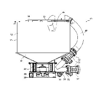
Figures Ito 3 show an exemplary embodiment of a colloidal mixer 10 according
to the
invention with a drum-shaped mixing trough 12, which is arranged on a frame
11. The
drum-shaped mixing trough 12 has a cylindrical inner surface 13 or inner wall
in its
upper portion, and is closed at its upper surface by a lid 14. A lower portion
of the
mixing trough 12 is formed by a conically configured bottom 16, which merges
via an
opening into a downwardly directed receptacle or recess 20 with a mixing
device 30.
The opening having the recess 20 is arranged eccentrically to a center axis of
the
cylindrical upper section of the mixing trough 12, as can be seen clearly in
Fig. 3.
The mixing device 30 in the recess 20 on the underside of the mixing trough 12
has a
rotationally driven mixing rotor 32 with a rotor hub 33 and radially oriented
mixing
blades 34 attached thereto. Altogether, the mixing rotor 32 with the mixing
blades 34
is configured such that at least one liquid component introduced into the
mixing trough
12 is mixed with at least one pulverulent solid component supplied into the
mixing
trough 12 by means of the rotating mixing rotor 32. In this case, a
circumferential speed
of the mixing rotor 32 is set in such a way and the shape of the mixing blades
34 is
designed in such a way that cavities are formed in a targeted manner in the at
least
one liquid or the mixture forming, which further support a mixing effect and a
fine
distribution of air.
The at least one liquid or the forming mixture is discharged by means of the
rotationally
driven mixing rotor 32 to a lateral outlet opening 22 with a Y-pipe section
24, at the two
Date Recue/Date Received 2023-10-16
- 13 -
outlet connections of which a backflow line 40 on the one hand and a discharge
line
50 on the other hand are arranged. An actuator 38 can be used to control
whether the
mixture formed is returned to the mixing trough 12 via the backflow line 40
for
continuation of the mixing process or is discharged from the colloidal mixer
10 via the
discharge line 50.
For forming the actuator 38, a first pinch valve 42 is arranged on the
backflow line 40
and a second pinch valve 52 is arranged on the discharge line 50, which can be
closed
or opened in particular by supplying a pressure medium, in particular
compressed air.
When the first pinch valve 42 is open and the second pinch valve 52 is closed,
liquid
or mixture is returned again from the Y-pipe section 24 to an upper portion of
the mixing
trough 12 via the backflow line 40 through a feed opening 15 in the lid 14, as
illustrated
clearly in Figures 2 and 3.
In this case, the free end of the backflow line 40 has a deflecting tube or
port opening
44, which is directed towards the inner side 13 of the mixing trough 12. As a
result of
the of the liquid or mixture exiting the port opening 44 and impinging on the
inner side
13 of the mixing trough 12, ambient air is finely dispersed incorporated in
the liquid or
mixture. This is supported by the fact that the backflow is divided into two
partial flows
by the orientation of the port opening 44, which flow along the inner side 13
of the
mixing trough 12 in opposite directions in the circumferential direction. At a
flow velocity
of several meters per second, the partial flows can thus meet again in an
opposite area
on the inner side 13 of the mixing trough 12, wherein further air is
incorporated into the
liquid or mixture by additional swirl.
The incorporation and fine distribution of the air is further increased by the
rotating
motion of the mixing rotor 32 with the mixing blades 34, as already described
above.
The mixing process can preferably last between 100 seconds to 200 seconds.
Once a desired consistency or homogeneity of the mixture has been achieved,
the first
pinch valve 42 on the backflow line 40 can be closed and the second pinch
valve 52
on the discharge line 50 can be opened. In this manner, the ready formed
mixture or
slurry is discharged from the colloidal mixer 10 through the discharge line 50
and out
Date Recue/Date Received 2023-10-16
- 14 -
of the outlet opening 22 by the pumping action of the mixing device 30.
After emptying the mixing trough 12, another mixing process for a new batch
can be
started.
Figures 4 to 7 show a possible embodiment for a mixing blade 34, which can be
used
on a mixing rotor 32 of a mixing device 30 of the colloidal mixer 10 described
above.
For fastening the mixing blade 34 to a rotor hub 33 of the mixing rotor 32,
fastening
elements 37 are shown schematically on one fastening side. These elements
serve for
detachable fastening of the mixing blade 34 to the rotor hub 33. Fig. 6 shows
detail A
with the fastening element 37 of Fig. 4 in greater detail.
The mixing blade 34 is formed from a base metal sheet 35 with a thickness d,
as can
clearly be discerned in Fig. 5. The thickness d can range from 3 mm to 20 mm.
A hole
pattern 36 having a plurality of through holes is formed in the actual mixing
region of
the mixing blade 34. The side surfaces of the mixing blade 34 can be surface
treated.
A diameter of the through holes can range between 5 mm and 50 mm. The material
webs located between the through holes may have a size of a few mm. Overall,
the
hole pattern 36 with the through holes may form a total opening area which
accounts
for between 40% to 80% of the total face of the mixing blade 34.
Figure 7 shows a partial area of the hole pattern 36 in greater detail,
wherein the hole
pattern 36 is formed from a plurality of through holes arranged in rows next
to one
another in a grid. Grid or material webs with corresponding flow edges remain
between
the through holes, which ensure for good swirl and a particularly finely
distributed
formation of cavities over the surface of the mixing blade 34. In principle, a
web width
between the holes can be between 10% and 40%, preferably between 16% and 33%,
of the hole diameter. Here, a sheet thickness may be between 20% to 75%,
preferably
between 33% to about 66%, of the hole diameter. Preferably, the hole diameter
is
between 10 mm to 20 mm, more preferably about 12 mm.
Referring to Fig. 7, a lower corner portion of the mixing blade 34 may be
chamfered or
angled.
Date Recue/Date Received 2023-10-16