Note : Les descriptions sont présentées dans la langue officielle dans laquelle elles ont été soumises.
WO 2022/231885
PCT/ITS2022/025278
CONTAINER CLOSURE SYSTEM AND SEALING ASSEMBLIES FOR MAINTAINING
SEAL INTEGRITY AT Low STORAGE TEMPERATURES
CROSS-REFERENCE TO RELATED APPLICATIONS
[0001] This application claims the benefit of priority under 35 U.S.0 119 of
U.S.
Provisional Application Serial No. 63/179,719 filed on April 26, 2021, the
content of which is
relied upon and incorporated herein by reference in its entirety.
Field
100021 The present specification generally relates to container closure
systems, such as glass
containers for storing pharmaceutical compositions.
Technical Background
100031 Pharmaceutical containers, such as vials and syringes, are typically
sealed via a
stopper or other closure to preserve the integrity of the contained material.
Closures are
typically made of synthetic rubbers and other elastomers. Such materials
beneficially have
high permeation resistance and elasticity to facilitate insertion into the
container to seal the
container's interior. The elasticity of typically-used closure materials,
however, may reduce at
low temperatures. For example, synthetic rubbers currently in use as material
closures may
comprise transition temperatures that are greater than or equal to -70 C and
less than or equal
to -30 C. Below the transition temperature, closures constructed of such
synthetic rubbers may
behave as a solid and be unable to expand elastically to compensate for the
relatively large
difference between coefficients of thermal expansion of the glass and a
crimping cap used to
secure the closure to the container. Given this, existing sealing assemblies
for pharmaceutical
containers may fail at temperatures less than or equal to -30 C.
100041 Some biological materials (e.g., blood, serum, proteins, stem cells,
and other
perishable biological fluids) require storage at temperatures below the glass
transition
temperatures of conventional elastomers to remain useful. For example, certain
RNA-based
vaccines may require storage at dry-ice temperatures (e.g., approximately -80
C) or liquid
nitrogen temperatures (e.g., approximately -180 C) to remain active. Such low
temperatures
may result in dimensional changes in the closure components (e.g., the glass
or polymer
1
CA 03216893 2023- 10- 26
WO 2022/231885
PCT/US2022/025278
container, the stopper, an aluminium cap), leading to issues in the integrity
of the seal, and
potential contamination of the material stored therein.
SUMMARY
[0005] A first aspect of the present disclosure includes a sealed
pharmaceutical container
comprises a shoulder, a neck extending from the shoulder, and a flange
extending from the
neck. The flange comprises an underside surface extending from the neck, an
outer surface
extending from the underside surface, the outer surface defining an outer
diameter of the flange,
and a contact surface extending between the outer surface and an inner surface
defining an
opening in the sealed pharmaceutical container. The contact surface comprises
an inner edge
disposed proximate to the opening and an outer peripheral edge disposed
proximate to the outer
surface of the flange. The sealed pharmaceutical container comprises a sealing
assembly
comprising a stopper extending over the contact surface of the flange and
covering the opening,
and a cap securing the stopper to the flange. The stopper comprises a sealing
surface that is
secured in contact with the contact surface of the flange to form a seal
between the flange and
the stopper. An outer peripheral edge of the sealing surface is disposed at or
radially inward
of the outer peripheral edge of the contact surface of the flange
[0006] A second aspect of the present disclosure includes the sealed
pharmaceutical
container of according to the first aspect, wherein the contact surface
comprises a conical
region of an upper surface of the flange.
[0007] A third aspect of the present disclosure includes the sealed
pharmaceutical container
of according to any of the first through the second aspects, wherein the
contact surface
comprises comprises a surface roughness of less than or equal to 0.2 [ini
[0008] A fourth aspect of the present disclosure includes the sealed
pharmaceutical container
of according to any of the first through the third aspects, wherein the
contact surface is free of
surface height variations greater than or equal to 5.0 pm.
[0009] A fifth aspect of the present disclosure includes the sealed
pharmaceutical container
of according to any of the first through the fourth aspects, wherein the
flange further comprises
a fillet extending between the contact surface and the outer surface.
2
CA 03216893 2023- 10- 26
WO 2022/231885
PCT/US2022/025278
[0010] A sixth aspect of the present disclosure includes the sealed
pharmaceutical container
of according to any of the first through the fifth aspects, wherein the fillet
comprises a radius
of curvature that is less than or equal to 21% of a length of the contact
surface of the flange.
[0011] A seventh aspect of the present disclosure includes the sealed
pharmaceutical
container of according to any of the first through the sixth aspects, wherein
the outer peripheral
edge of the sealing surface is disposed radially inward of a transition
between the upper sealing
surface and the fillet.
[0012] A eighth aspect of the present disclosure includes the sealed
pharmaceutical container
of according to any of the first through the seventh aspects, wherein the
flange further
comprises a chamfer extending between the contact surface and the outer
surface at an angle
relative to the contact surface.
100131 A ninth aspect of the present disclosure includes the sealed
pharmaceutical container
of according to any of the first through the eighth aspects, wherein the angle
is less than or
equal to 300
.
[0014] A tenth aspect of the present disclosure includes the sealed
pharmaceutical container
of according to any of the first through the ninth aspects, wherein the outer
peripheral edge of
the sealing surface is disposed radially inward of a transition between the
upper sealing surface
and the chamfer.
[0015] An eleventh aspect of the present disclosure includes the sealed
pharmaceutical
container of according to any of the first through the tenth aspects, wherein
the upper sealing
surface extends at a flange angle relative to a plane extending through an end
of the opening.
[0016] A twelfth aspect of the present disclosure includes the sealed
pharmaceutical
container of according to any of the first through the eleventh aspects,
wherein the flange angle
is greater than or equal to 5 .
[0017] A thirteenth aspect of the present disclosure includes the sealed
pharmaceutical
container of according to any of the first through the twelfth aspects,
wherein the flange angle
is less than or equal to 300
.
[0018] A fourteenth aspect of the present disclosure includes the sealed
pharmaceutical
container of according to any of the first through the thirteenth aspects,
wherein: the cap
3
CA 03216893 2023- 10- 26
WO 2022/231885
PCT/US2022/025278
comprises a metallic portion crimped around the underside surface of the
flange and a plastic
portion retaining an upper portion the metallic portion on an upper surface of
the stopper, and
an inner edge of the metallic portion is inserted into the plastic portion
such that the upper
portion extends at a cap angle relative to the plane extending through the end
of the opening.
[0019] A fifteenth aspect of the present disclosure includes the sealed
pharmaceutical
container of according to any of the first through the fourteenth aspects,
wherein the flange
angle is within one degree of the cap angle.
[0020] A sixteenth aspect of the present disclosure includes the sealed
pharmaceutical
container of according to any of the first through the fifteenth aspects,
wherein the stopper is
compressed by the cap to provide a residual nominal strain of less than or
equal to 8%.
[0021] A seventeenth aspect of the present disclosure includes the sealed
pharmaceutical
container of according to any of the first through the sixteenth aspects,
wherein the sealing
assembly maintains the helium leakage rate of the sealed pharmaceutical
container of less than
or equal to 1.4x10' cm3/s as the sealed pharmaceutical container is cooled to
a temperature of
less than or equal to -80 C.
[0022] An eighteenth aspect of the present disclosure includes the sealed
pharmaceutical
container of according to any of the first through the seventeenth aspects,
wherein the sealing
surface maintains a contact area of greater than or equal to 10% of a total
surface area of the
contact surface as the sealed pharmaceutical container is cooled to a
temperature of less than
or equal to -80 C.
[0023] A nineteenth aspect of the present disclosure includes a sealed
pharmaceutical
container comprising a shoulder; a neck extending from the shoulder; and a
flange extending
from the neck, The flange comprises an underside surface extending from the
neck; an outer
surface extending from the underside surface, the outer surface defining an
outer diameter of
the flange; and an upper surface extending between the outer surface and an
inner surface
defining an opening in the sealed pharmaceutical container. The upper surface
comprises a
conical region extending between the opening and the outer surface, wherein
the conical region
is free of surface height deviations of greater than or equal to 5 p.m; and a
transition region
extending between the conical region and the outer surface. The sealed
pharmaceutical
container comprises a sealing assembly comprising. a stopper covering the
opening; and cap
crimped to the underside surface of the flange so as to compress a sealing
surface of the stopper
4
CA 03216893 2023- 10- 26
WO 2022/231885
PCT/US2022/025278
against the conical region such that an outer peripheral edge of the sealing
surface contacts the
conical region.
[0024] A twentieth aspect of the present disclosure includes a sealed
pharmaceutical
container according to the nineteenth aspect, wherein the contact surface
comprises comprises
a Ra value of less than or equal 5 nm.
[0025] A twenty first aspect of the present disclosure includes a sealed
pharmaceutical
container according to any of the nineteenth through the twentieth aspects,
wherein the sealing
surface maintains a contact area of greater than or equal to 10% of a total
surface area of the
upper surface as the sealed pharmaceutical container is cooled to a
temperature of less than or
equal to -80 C.
[0026] A twenty second aspect of the present disclosure includes a sealed
pharmaceutical
container according to any of the nineteenth through the twenty first aspects,
wherein the
transition region comprises a fillet having a radius of curvature that is less
than or equal to 21%
of a width of the conical section.
[0027] A twenty third aspect of the present disclosure includes a sealed
pharmaceutical
container according to any of the nineteenth through the twenty second
aspects, wherein the
radius of curvature is less than or equal to 0.5 mm.
[0028] A twenty fourth aspect of the present disclosure includes a sealed
pharmaceutical
container according to any of the nineteenth through the twenty third aspects,
wherein the
transition region comprises a chamfer extending at an angle relative to the
conical region.
[0029] A twenty fifth aspect of the present disclosure includes a sealed
pharmaceutical
container according to any of the nineteenth through the twenty fourth
aspects, wherein the
angle is less than or equal to 30 .
[0030] A twenty sixth aspect of the present disclosure includes a sealed
pharmaceutical
container according to any of the nineteenth through the twenty fifth aspects,
wherein the
conical portion extends at a flange angle relative to a plane extending
through an end of the
opening that is greater than or equal to 5'.
CA 03216893 2023- 10- 26
WO 2022/231885
PCT/US2022/025278
[0031] A twenty seventh aspect of the present disclosure includes a sealed
pharmaceutical
container according to any of the nineteenth through the twenty sixth aspects,
wherein the
flange angle is less than or equal to 300
.
[0032] A twenty eighth aspect of the present disclosure includes a sealed
pharmaceutical
container according to any of the nineteenth through the twenty seventh
aspects, wherein: the
cap comprises a metallic portion crimped around the underside surface of the
flange and a
plastic portion retaining an upper portion the metallic portion on an upper
surface of the
stopper, and an inner edge of the metallic portion is inserted into the
plastic portion such that
the upper portion extends at a cap angle relative to the plane extending
through the end of the
opening.
[0033] A twenty ninth aspect of the present disclosure includes a sealed
pharmaceutical
container according to any of the nineteenth through the twenty eighth
aspects, wherein the
flange angle is within one degree of the cap angle.
[0034] A thirtieth aspect of the present disclosure includes a sealed
pharmaceutical container
according to any of the nineteenth through the twenty ninth aspects, wherein
the stopper is
compressed by the cap to provide a residual nominal strain of less than or
equal to 8%.
[0035] A thirty first aspect of the present disclosure includes a sealed
pharmaceutical
container according to any of the nineteenth through the thirtieth aspects,
wherein the sealing
assembly maintains the helium leakage rate of the sealed pharmaceutical
container of less than
or equal to 1.4x10' cm3/s as the sealed pharmaceutical container is cooled to
a temperature of
less than or equal to -80 C.
[0036] A thirty second aspect of the present disclosure includes a sealed
pharmaceutical
container according to any of the nineteenth through the thirty first aspects,
wherein the sealing
surface maintains a contact area of greater than or equal to 20 mm2 with the
contact surface as
the sealed pharmaceutical container is cooled to a temperature of less than or
equal to -80 C.
[0037] A thirty third aspect of the present disclosure includes a method of
sealing a sealed
pharmaceutical container, the method comprising the steps of: providing a
sealed
pharmaceutical container comprising a shoulder, a neck extending from the
shoulder and a
flange extending from the neck, the flange comprising: an underside surface
extending from
the neck; an outer surface extending from the underside surface, the outer
surface defining an
6
CA 03216893 2023- 10- 26
WO 2022/231885
PCT/US2022/025278
outer diameter of the flange; and an upper surface extending between the outer
surface to an
inner surface of the sealed pharmaceutical container that defines an opening,
the upper surface
comprising a conical region; inserting a pharmaceutical composition into the
sealed
pharmaceutical container; providing a sealing assembly comprising a stopper
extending over
the upper surface of the flange and covering the opening; crimping a metal-
containing cap over
the stopper and against flange to thereby compress the stopper against the
upper surface such
that an outer peripheral edge of a sealing surface of the stopper contacts the
conical region; and
cooling the sealed pharmaceutical container to a temperature of less than or
equal to -45 C,
wherein, after the cooling of the sealed pharmaceutical container, the
compression is
maintained on the sealing surface such that a helium leakage rate of the
sealed pharmaceutical
container is less than or equal to 1.4x10' cm3/s at the temperature.
[0038] A thirty fourth aspect of the present disclosure includes a method
according to the
thirty third aspect, wherein the metal-containing cap is crimped such that the
stopper is
compressed against the upper surface to provide a residual nominal strain of
less than or equal
to 8%.
[0039] A thirty fifth aspect of the present disclosure includes a method
according to any of
the thirty third to the thirty fourth aspects, wherein a contact area between
the sealing surface
of the stopper and the upper surface of the flange is greater than or equal to
10% of a total
surface area of the upper surface when the sealed pharmaceutical container is
cooled to the
temperature.
[0040] A thirty sixth aspect of the present disclosure includes a method
according to any of
the thirty third to the thirty fifth aspects, wherein the temperature is less
than or equal to -80 C.
[0041] A thirty seventh aspect of the present disclosure includes a method
according to any
of the thirty third through the thirty sixth aspects, wherein the temperature
is less than or equal
to -180 C.
[0042] A thirty eighth aspect of the present disclosure includes a method
according to any
of the thirty third through the thirty seventh aspects, wherein: the upper
surface further
comprises a transition region extending between the conical region and the
outer surface of the
flange, and the outer peripheral edge of the sealing surface does not contact
the transition region
as a result of the compression of the stopper.
7
CA 03216893 2023- 10- 26
WO 2022/231885
PCT/US2022/025278
[0043] A thirty ninth aspect of the present disclosure includes a method
according to any of
the thirty third through the thirty eighth aspects, wherein the transition
region comprises a fillet
having a radius of curvature of less than 1.0 mm.
[0044] A fortieth aspect of the present disclosure includes a method according
to any of the
thirty third through the thirty ninth aspects, wherein the radius of curvature
is less than or equal
to 0.5 mm.
[0045] A forty first aspect of the present disclosure includes a method
according to any of
the thirty third through the fortieth aspects, wherein the transition region
comprises a chamfer
extending at an angle of less than or equal to 300 relative to the conical
region.
[0046] A forty second aspect of the present disclosure includes a method
according to any
of the thirty third through the forty first aspects, wherein the conical
region extends at a flange
angle relative to a plane extending through an end of the opening that is
greater than or equal
to 5 .
[0047] A forty third aspect of the present disclosure includes a method
according to any of
the thirty third through the forty second aspects, wherein. the metal-
containing cap comprises
a metallic portion crimped around the underside surface of the flange and a
plastic portion
retaining an upper portion the metallic portion on an upper surface of the
stopper, and an inner
edge of the metallic portion is inserted into the plastic portion such that
the upper portion
extends at a cap angle relative to the plane extending through the end of the
opening.
[0048] A forty fourth aspect of the present disclosure includes a method
according to any of
the thirty third through the forty third aspects, wherein the flange angle is
within one degree of
the cap angle.
[0049] A forty fifth aspect of the present disclosure includes a method
according to any of
the thirty third through the forty fourth aspects, wherein the sealed
pharmaceutical container is
cooled to the temperature at a rate of less than or equal to 3 C per minute.
[0050] A forty sixth aspect of the present disclosure includes a glass
container comprising:
a shoulder; a neck extending from the shoulder; and a flange extending from
the neck, the
flange comprising: an underside surface extending from the neck; an outer
surface extending
from the underside surface, the outer surface defining an outer diameter of
the flange; and an
8
CA 03216893 2023- 10- 26
WO 2022/231885
PCT/US2022/025278
upper surface extending between the outer surface and an inner surface
defining an opening in
the glass container, wherein the upper surface comprises: a conical region
extending between
the opening and the outer surface, wherein the conical region is free of
surface height deviations
of greater than or equal to 5 Mm; and a transition region extending between
the conical region
and the outer surface, wherein at least one of. the transition region
comprises a chamfer
extending at a chamfer angle relative to the upper surface that is less than
or equal to 300 or a
fillet comprising a fillet radius rf that is less than or equal to 0.8 mm, and
the conical region
extends at a flange angle relative to a plane extending through an end of the
opening that is
greater than or equal to 5'.
[0051] A forty seventh aspect includes the glass container according to the
forty sixth aspect,
wherein: the transition region comprises the chamfer, and the chamfer angle is
less than or
equal to 10
[0052] A forty eighth aspect of the present disclosure includes a glass
container according
to any of the forty sixth through the forty seventh aspects, wherein- the
transition region
comprises the fillet, and the fillet radius is less than or equal to 21% of a
width of the conical
section.
[0053] A forty ninth aspect of the present disclosure includes a glass
container according to
any of the forty sixth through the forty eighth aspects, wherein: the conical
region extends at
the flange angle relative to the plane, and the angle is greater than or equal
to 5 and less than
or equal to 20 .
BRIEF DESCRIPTION OF THE DRAWINGS
[0054] The embodiments set forth in the drawings are illustrative and
exemplary in nature
and not intended to limit the subject matter defined by the claims. The
following detailed
description of the illustrative embodiments can be understood when read in
conjunction with
the following drawings, where like structure is indicated with like reference
numerals and in
which:
[0055] FIG. 1 schematically depicts a cross-sectional view of a sealed glass
container,
according to one or more embodiments described herein;
9
CA 03216893 2023- 10- 26
WO 2022/231885
PCT/US2022/025278
[0056] FIG. 2A schematically depicts a portion of a glass container including
a fillet
extending between upper and outer surfaces of a flange, according to one or
more embodiments
described herein;
[0057] FIG. 2B schematically depicts a portion of a stopper compressed against
the upper
surface of the flange depicted in FIG. 2A, according to one or more
embodiments described
herein;
[0058] FIG. 3A schematically depicts a portion of a portion of a glass
container including a
chamfer extending between upper and outer surfaces of a flange, according to
one or more
embodiments described herein;
[0059] FIG. 3B schematically depicts a portion of a stopper compressed against
the upper
surface of the flange depicted in FIG. 3A, according to one or more
embodiments described
herein;
[0060] FIG. 4A schematically depicts a portion of a glass container including
an upper
surface extending at a flange angle to a plane extending through an end of an
opening of the
glass container, according to one or more embodiments described herein;
[0061] FIG. 4B schematically depicts a portion of a stopper compressed against
the upper
surface of the glass container depicted in FIG. 4A, according to one or more
embodiments
described herein;
[0062] FIG. 5A depicts simulation results of a portion of a stopper compressed
against an
upper surface of a first glass container including an upper surface of a
flange that extends at a
first flange angle from a plane extending through an end of the opening of the
first glass
container, according to one or more embodiments described herein;
[0063] FIG. 5B depicts simulation results of a portion of a stopper compressed
against the
upper surface of the flange of the first glass container of FIG. 5A when
cooled to a temperature
of -80 C, according to one or more embodiments described herein;
[0064] FIG. 5C depicts simulation results of a portion of a stopper compressed
against an
upper surface of a flange a second glass container that extends at a second
flange angle from a
plane extending through an end of the opening of the second glass container,
according to one
or more embodiments described herein;
CA 03216893 2023- 10- 26
WO 2022/231885
PCT/US2022/025278
[0065] FIG. 5D depicts simulation results of a portion of a stopper compressed
against the
upper surface of the second glass container of FIG. 5C when cooled to a
temperature of -80 C,
according to one or more embodiments described herein;
[0066] FIG. 5E depicts simulation results of a portion of a stopper compressed
against an
upper surface of a flange of a third glass container that extends at a third
flange angle from a
plane extending through an end of the opening of the third glass container,
according to one or
more embodiments described herein;
[0067] FIG. 5F depicts simulation results of a portion of a stopper compressed
against the
upper surface of the third glass container of FIG. 5E when cooled to a
temperature of -80 C,
according to one or more embodiments described herein;
[0068] FIG. 5G depicts simulation results of a portion of a stopper compressed
against an
upper surface of a flange of a fourth glass container that extends at a fourth
flange angle from
a plane extending through an end of the opening of the fourth glass container,
according to one
or more embodiments described herein;
[0069] FIG. 5T-1 depicts simulation results of a portion of a stopper
compressed against the
upper surface of the fourth glass container of FIG. 5G when cooled to a
temperature of -80 C,
according to one or more embodiments described herein;
[0070] FIG. 6A depicts a plot of contact area between stoppers and upper
surfaces of a
plurality of glass containers with a 20 mm flange finish including different
flange angles as a
function of temperature, according to one or more embodiments described
herein;
[0071] FIG. 6B depicts a plot of contact area between the stoppers and glass
containers
described with respect to FIG. 6A as a function of flange angle when the glass
containers are
cooled to -80 C, according to one or more embodiments described herein;
[0072] FIG. 7A depicts simulation results of a portion of a stopper compressed
against an
upper surface of a first glass container including a chamfer extending at a
first angle to an upper
surface of a flange, according to one or more embodiments described herein;
[0073] FIG. 7B depicts simulation results of a portion of a stopper compressed
against the
upper surface of the first glass container of FIG. 7A when cooled to a
temperature of -80 C,
according to one or more embodiments described herein;
11
CA 03216893 2023- 10- 26
WO 2022/231885
PCT/US2022/025278
[0074] FIG. 7C depicts simulation results of a portion of a stopper compressed
against an
upper surface of a second glass container including a chamfer extending at a
second angle to
an upper surface of a flange, according to one or more embodiments described
herein;
[0075] FIG. 7D depicts simulation results of a portion of a stopper compressed
against the
upper surface of the second glass container of FIG. 7C when cooled to a
temperature of -80 C,
according to one or more embodiments described herein;
[0076] FIG. 7E depicts simulation results of a portion of a stopper compressed
against an
upper surface of a third glass container including a chamfer extending at a
third angle to an
upper surface of a flange, according to one or more embodiments described
herein;
[0077] FIG. 7F depicts simulation results of a portion of a stopper compressed
against the
upper surface of the third glass container of FIG. 7E when cooled to a
temperature of -80 C,
according to one or more embodiments described herein;
[0078] FIG. 8A depicts simulation results of a portion of a stopper compressed
against an
upper surface of a first glass container including a fillet at an outer
diameter thereof having a
first radius of curvature at a temperature of 25 C, according to one or more
embodiments
described herein;
[0079] FIG. 8B depicts simulation results of a portion of a stopper compressed
against an
upper surface of a second glass container including a fillet at an outer
diameter thereof having
a second radius of curvature at a temperature of 25 C, according to one or
more embodiments
described herein;
[0080] FIG. 8C depicts simulation results of a portion of a stopper compressed
against the
upper surface of the first class container of FIG. 8A when cooled to a
temperature of -80 ,
according to one or more embodiments described herein;
[0081] FIG. 8D depicts simulation results of a portion of a stopper compressed
against the
upper surface of the second class container of FIG. 8B when cooled to a
temperature of -80 ,
according to one or more embodiments described herein;
[0082] FIG. 8E depicts simulation results of a portion of a stopper compressed
against the
upper surface of the first class container of FIG. 8A when cooled to a
temperature of -180 ,
according to one or more embodiments described herein;
12
CA 03216893 2023- 10- 26
WO 2022/231885
PCT/US2022/025278
[0083] FIG. 8F depicts simulation results of a portion of a stopper compressed
against the
upper surface of the second class container of FIG. 8B when cooled to a
temperature of -180 ,
according to one or more embodiments described herein; and
[0084] FIG. 9 depicts a plot of contact areas between stoppers and glass
containers having
different fillet radii as a function of temperature, according to one or more
embodiments
described herein.
DETAILED DESCRIPTION
[0085] Reference will now be made in detail to embodiments of sealed
pharmaceutical
containers comprising sealing assemblies that maintain container closure
integrity at relatively
low storage temperatures (e.g., less than or equal to -30 C, less than or
equal to -40 C, less
than or equal to -50 C, less than or equal to -60 C, less than or equal to -70
C, less than or
equal to -80 C, less than or equal to -100 C, less than or equal to 125 C,
less than or equal to
-150 C, less than or equal to -175 C, -180 C). To facilitate maintenance of
container closure
integrity at such low storage temperatures, the sealed glass containers
described herein may
include a flange that is designed such that, when a crimping process is used
to compress a
sealing surface of a stopper against an upper surface of the flange, an outer
peripheral edge of
the sealing surface contacts the upper surface. The upper surface of the
flange may comprise
a relatively low surface roughness (e.g., comprise an Ra value of less than or
equal to 5 nm)
and be free of surface height variations and defects to facilitate seal
formation with the stopper.
In embodiments, the outer peripheral edge of the sealing surface may be
disposed at or radially
inward of an outer peripheral edge of the upper surface of the flange to
ensure a continuous
contact area between the stopper and the flange starting at the outer
peripheral edge of the
sealing surface. In embodiments, such positioning of the outer peripheral edge
of the sealing
surface in contact with the upper surface beneficially maintains a contact
area between the
stopper and upper surface at greater than or equal to 10% of a total surface
area of the upper
surface at such low storage temperatures, thereby lessening the probability of
seal breakage as
compared to existing glass containers. Without wishing to be bound by theory,
it is believed
that such placement of the outer peripheral edge of the sealing surface of the
stopper facilitates
more uniform compression of the stopper via capping by avoiding a
concentration of
compression at the outer diameter of the stopper.
13
CA 03216893 2023- 10- 26
WO 2022/231885
PCT/US2022/025278
[0086] Various structural modifications to existing pharmaceutical glass
containers may be
made to achieve the beneficial relative positioning between the outer
peripheral edges of the
stopper sealing surface and upper surface of the flange described herein. For
example, when
an outer diameter of the flange is fixed at a standard, commonly used diameter
(e.g., 13 mm,
20 mm), such relative positioning may be achieved by fabricating glass
containers such that a
radial extent of a transition region between the upper surface of the flange
and an outer surface
of the flange is diminished as compared to existing pharmaceutical glass
containers. In
embodiments, the radial extent of the transition region is diminished by
limiting a radius of
curvature of a fillet extending between upper and outer surfaces of the flange
to less than one-
third (e.g., less than or equal to 21%) of a width of the upper surface (e.g.,
less than or equal to
0.8 mm, less than or equal to 0.7 mm, less than or equal to 0.6 mm, less than
or equal to 0.5
mm, less than or equal to 0.4 mm, less than or equal to 0.3 mm, less than or
equal to 0.2 mm).
In embodiments, the radial extent of the transition region is diminished by
maintaining a
chamfer angle of a chamfer extending between the upper and outer surfaces to
less than or
equal to 30' (e.g., less than or equal to 25 , less than or equal to 20 , less
than or equal to 15 ,
less than or equal 100, less than or equal to 5 ). In embodiments, when the
outer dimeter of
the flange is fixed at a standard, commonly used value, the relative
positioning between the
outer peripheral edges of the stopper sealing surface and the upper surface of
the flange may
be obtained by increasing a flange angle at which the upper surface extends
relative to a plane
extending through an end of an opening of the glass container over existing
pharmaceutical
glass containers. In embodiments, the upper surface of the flange may extend
at a flange angle
that is greater than or equal to 5' (e.g., 6 , 7 , 8 , 9 , 100,110, 12, 13 ,
14 , 15 , 16 , 17 , 18 ,
19 , 20 , and any values lying between such flange angles). Such increased
flange angles
increase the surface area of the upper surface, thereby facilitating placement
of the outer
peripheral edge of the sealing surface of the stopper radially inward of the
transition region
between the upper surface and the outer surface.
[0087] The pharmaceutical glass containers described herein may further be
beneficial over
existing pharmaceutical glass containers in that they are capable of
maintaining seals at low
storage temperatures with lower amounts of stopper compression during crimping
processes.
Existing pharmaceutical containers may be sealed with crimping processes
resulting in residual
seal forces at the upper surfaces of the flange that are greater than 20 lbf
(e.g., greater than or
equal to 25 lbf, resulting in compression of the stopper that is greater than
10% and less than
or equal to 20%). The improved seals provided by the pharmaceutical glass
containers
14
CA 03216893 2023- 10- 26
WO 2022/231885
PCT/US2022/025278
described herein may be capable of maintaining container closure integrity at
lower residual
forces (e.g., resulting in the stopper having a residual nominal strain of
less than or equal to 8%
after crimping). Such a reduction in residual seal force may facilitate use of
more simple and
efficient crimping processes, thereby lowering production costs.
[0088] As used herein, the term "surface roughness" refers to an Ra value or
an Sa value.
An Ra value is a measure of the arithmetic average value of a filtered
roughness profile
determined from deviations from a centerline of the filtered roughness. For
example, an Ra
value may be determined based on the relation:
1 n
Ra = -n ¨ IcLI (1)
where Hi is a surface height measurement of the surface and HCL corresponds to
a centerline
(e.g., the center between maximum and minimum surface height values) surface
height
measurement among the data points of the filtered profile. An Sa value may be
determined
through a real extrapolation of equation 1 herein. Filter values (e.g., cutoff
wavelengths) for
determining the Ra or Sa values described herein may be found in ISO ISO 25718
(2012).
Surface height may be measured with a variety of tools, such as an optical
interferometer,
stylus-based profilometer, or laser confocal microscope. To assess the
roughness of surfaces
described herein (e.g., sealing surfaces or portions thereof), measurement
regions should be
used that are as large as is practical, to assess variability that may occur
over large spatial
scales.
[0089] As used herein, the term "container closure integrity" refers to
maintenance of a seal
at an interface between a glass container and a sealing assembly (e.g.,
between a sealing surface
of a glass container and a stopper) that is free of gaps above a threshold
size to maintain a
probability of contaminant ingress or reduce the possibility of gas
permeability below a
predetermined threshold based on the material stored in a glass container. For
example, in
embodiments, a container closure integrity is maintained if a helium leakage
rate during a
helium leak test described in USP <1207> (2016) at less than or equal to
1.4x106 cm3/s.
[0090] As used herein, the term "about- means that amounts, sizes,
formulations,
parameters, and other quantities and characteristics are not and need not be
exact, but may be
approximate and/or larger or smaller, as desired, reflecting tolerances,
conversion factors,
rounding off, measurement error and the like, and other factors known to those
of skill in the
CA 03216893 2023- 10- 26
WO 2022/231885
PCT/US2022/025278
art. When the term "about" is used in describing a value or an end-point of a
range, the specific
value or end-point referred to is included. Whether or not a numerical value
or end-point of a
range in the specification recites "about," two embodiments are described: one
modified by
"about," and one not modified by "about." It will be further understood that
the endpoints of
each of the ranges are significant both in relation to the other endpoint, and
independently of
the other endpoint.
[0091] Directional terms as used herein - for example up, down, right, left,
front, back, top,
bottom - are made only with reference to the figures as drawn and are not
intended to imply
absolute orientation.
[0092] As used herein, the singular forms "a," "an" and "the" include plural
referents unless
the context clearly dictates otherwise. Thus, for example, reference to -a"
component includes
aspects having two or more such components, unless the context clearly
indicates otherwise.
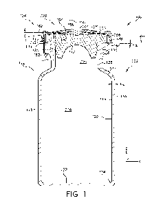
[0093] Referring now to FIG. 1, one embodiment of a sealed pharmaceutical
container 100
for storing a pharmaceutical formulation is schematically depicted in cross
section. The sealed
pharmaceutical container 100 comprises a glass container 102 and a sealing
assembly 104
coupled to the glass container 102 via an opening 105 of the glass container
102. The glass
container 102 generally comprises a body 112. The body 112 extends between an
inner surface
114 and an outer surface 116 of the glass container 102, includes a central
axis A, and generally
encloses an interior volume 118. In the embodiment of the glass container 102
shown in FIG.
1, the body 112 generally comprises a wall portion 120 and a floor portion
122. The wall
portion 120 transitions into the floor portion 122 through a heel portion 124.
In the depicted
embodiment, the glass container 102 includes a flange 126, a neck 128
extending from the
flange 126, a barrel 115, and a shoulder 130 extending between the neck 128
and the barrel
115. In embodiments, the glass container 102 is symmetrical about a central
axis A, with each
of the barrel 115, neck 128, and flange 126, being substantially cylindrical-
shaped. The body
112 has a wall thickness Tw which extends between the inner surface 114 to the
outer surface
116, as depicted in FIG. 1.
[0094] In embodiments, the glass container 102 may be formed from Type I, Type
II or Type
TTI glass as defined in USP <660>, including borosilicate glass compositions
such as Type 1B
borosilicate glass compositions under USP <660>. Alternatively, the glass
container 102 may
be formed from alkali aluminosilicate glass compositions such as those
disclosed in U.S. Patent
16
CA 03216893 2023- 10- 26
WO 2022/231885
PCT/US2022/025278
No. 8,551,898, hereby incorporated by reference in its entirety, or alkaline
earth aluminosilicate
glasses such as those described in U.S. Patent No. 9,145,329, hereby
incorporated by reference
in its entirety. In embodiments, the glass container 102 may include a coating
such as a heat
tolerant coating disclosed in U.S. Patent No. 10,0273,049, hereby incorporated
by reference in
its entirety. In embodiments, the glass container 102 may be constructed from
a soda lime
glass composition. In embodiments, the glass container 102 is constructed of a
glass
composition having a coefficient of thermal expansion that is greater than or
equal to 0x107/K
and less than or equal to 100x10-7/K (e.g., greater than or equal to 30 x 10-
7/K and less than or
equal to 70x10-7/K).
[0095] While the glass container 102 is depicted in FIG. 1 as having a
specific form-factor
(i.e., a vial), it should be understood that the glass container 102 may have
other form factors,
including, without limitation, Vacutainers , cartridges, syringes, ampoules,
bottles, flasks,
phials, tubes, beakers, or the like. Further, it should be understood that the
glass containers
described herein may be used for a variety of applications including, without
limitation, as
pharmaceutical packages, beverage containers, or the like.
[0096] The wall thickness Tw of the glass container 102 may vary depending on
the
implementation. In embodiments, the wall thickness Tw of the glass container
102 may be
from less than or equal to 6 millimetres (mm), such as less than or equal to 4
mm, less than or
equal to 2 mm, less than or equal to 1.5 mm or less than or equal to 1 mm. In
some
embodiments, the wall thickness T may be greater than or equal to 0.1 mm and
less than or
equal to 6 mm, greater than or equal to 0.3 mm and less than or equal to 4 mm,
greater than or
equal to 0.5 mm and less than or equal to 4 mm, greater than or equal to 0.5
mm and less than
or equal to 2 mm, or greater than or equal to 0.5 mm and less than or equal to
1.5 mm. In
embodiments, the wall thickness Tw may be greater than or equal to 0.9 mm and
less than or
equal to 1.8 mm. The wall thickness Tw may vary depending on the axial
location within the
glass container 102.
[0097] As depicted in FIG. 1, the flange 126 comprises an underside surface
132, an outer
surface 136, and an upper surface 138. The outer surface 136 may define an
outer diameter of
the flange 126_ In embodiments, the outer diameter is 13 mm, 20 mm or between
13 mm and
20 mm. In embodiments, the upper surface 138 is a conical surface comprising
an inner edge
140 (e.g., delineating a boundary of the opening 105) and an outer peripheral
edge 142. In
embodiments, the upper surface 138 of the flange 126 comprises an upper
surface of the glass
17
CA 03216893 2023- 10- 26
WO 2022/231885
PCT/US2022/025278
container 102 extending between the inner edge 140 and the outer peripheral
edge 142. The
inner and outer edges 140 and 142 may mark transition points where the
exterior surface of the
glass container 102 deviates from a conical surface by more than surface
height variations
associated with a surface roughness of the upper surface 138. In embodiments,
the upper
surface 138 comprises a relatively low surface roughness (e.g., an Ra value of
less than or equal
nm) and is free of surface defects and surface height deviations of greater
than or equal to 5
[tm from the conical surface. Such uniformity of the upper surface 138
beneficially facilitates
maintaining contact between the upper surface 138 and a stopper (e.g., the
stopper 106
described herein) to maintain a seal when the glass container 102 is cooled to
relatively low
temperatures (e.g., to less than or equal to -45 C, less than or equal to -80
C, less than or equal
to -180 C). In embodiments, the sealed pharmaceutical containers may be cooled
to the low
storage temperatures described herein at rates of less than or equal to 3 C
per minute.
[0098] In embodiments, the flange 126 further comprises a transition region
144 extending
between the upper surface 138 and the outer surface 136. In embodiments,
within the transition
region 144, the outer surface 116 of the glass container 102 deviates from the
conical surface
followed by the upper surface 138 and a second surface (e.g., cylindrical
surface) followed by
the outer surface 136. The transition region 144 may take a variety of forms
depending on the
implementation. In embodiments, the transition region 144 comprises a corner
such that the
outer surface 116 directly transitions from the upper surface 138 to the outer
surface 136. In
embodiments, the transition region 144 comprises a chamfer extending at a
chamfer angle from
the upper surface 138. In embodiments, the transition region 144 comprises a
fillet comprising
a radius of curvature (rf). As will be described in greater detail herein, the
relative positioning
of the transition region 144 and a sealing surface of a stopper (e.g., the
stopper 106 described
herein) is an important factor to ensure that the sealed pharmaceutical
container 100 maintains
closure integrity at relatively low storage temperatures.
[0099] In embodiments, each cross-section of the upper surface 138 of the
flange 126
extends at a flange angle a relative to a plane 146 extending through an end
of the opening 105
of the glass container 102. In embodiments, the plane 146 contacts (e.g., lies
on top of) a most
distant portion of the glass container 102 from the floor portion 122 along
the axis A. In
embodiments, the most distant portion comprises the inner edge 140 of the
upper surface 138
of the flange 126. In embodiments, the plane 146 extends perpendicular to the
axis A. As
described in greater detail herein, the greater the flange angle a, the
greater the surface area of
18
CA 03216893 2023- 10- 26
WO 2022/231885
PCT/US2022/025278
the upper surface 108, which renders the transition region 144 more distant
from the inner edge
140 along the upper sealing surface 146. As described in greater detail
herein, such distance
between the transition region 144 and the inner edge 140 may beneficially
ensure an outer
peripheral edge of a sealing surface of a stopper is disposed radially inward
of the transition
region 144, which may ensure maintenance of container closure integrity at
relatively low
storage temperatures. In embodiments, the flange angle a may vary between -2'
and 300
depending on the implementation.
[00100] Referring still to FIG. 1, the sealing assembly 104 comprises a
stopper 106 and a cap
assembly 108. The stopper 106 may be constructed of a suitable elastomeric
material (e.g.,
Butyl rubber). In the embodiment depicted in FIG. 1, the stopper 106 comprises
an insertion
portion 117 and a sealing portion 119 comprising a sealing surface 121. The
insertion portion
117 is inserted into the opening 105 of the glass container 102 until the
sealing surface 121
contacts an upper sealing surface (e.g., the upper surface 138 of the flange
126) of the glass
container 102. The sealing portion 119 is then pressed against the upper
surface 138 via
crimping the cap assembly 108 to form a seal between the sealing surface 121
and the upper
surface 138 of the flange 126.
[00101] The cap assembly 108 is depicted to include a metallic portion 148 and
a plastic
portion 150. The metallic portion 148 is crimped around the underside surface
132 of the
flange 126 such that an underlying portion 152 thereof contacts the underside
surface 132. In
embodiments, the length of the underlying portion 152 of the metallic portion
148 that directly
contacts the underside surface 132 of the flange 126 possesses a length (e.g.,
in the X-direction
depicted in FIG. 1) that is greater than or equal to 1 mm to facilitate
maintenance of residual
sealing force within the stopper 106 at storage temperatures of less than or
equal to -80 C. In
embodiments, the plastic portion 150 includes a retention feature 154 (e.g., a
slot, cavity, dip,
hole, or the like ) receiving an inner edge 156 of the metallic portion 148 to
retain an upper
portion 158 of the metallic portion 148 on an upper surface 160 of the stopper
106. In
embodiments, the retention feature 154 of the plastic portion 150 is oriented
such that the upper
portion 158 extends at a cap angle B relative to a plane 162 extending
perpendicular to the axis
A. The cap angle B beneficially ensures a downward compression against the
upper surface
160 of the stopper 106 to compress the sealing surface 121 against the upper
surface 138 and
facilitate seal formation.
19
CA 03216893 2023- 10- 26
WO 2022/231885
PCT/US2022/025278
[00102] In embodiments, during the crimping process, the stopper 106 is
inserted into the
opening 105 and a compression force is applied to the metallic portion 148
during crimping.
Compression of the stopper 106 generates a residual sealing force within the
flange 126 that
maintains compression on the stopper 106 after the metallic portion 148 is
crimped into place.
In embodiments, the residual seal force may vary from 5 lbf to 25 lbf and
result in nominal
stopper strains between 5% and 19%.
[00103] In embodiments, various aspects of the glass container 102 and cap
assembly 108
have been designed to maintain container closure integrity at relatively low
storage
temperatures. As depicted in FIG. 1, the sealing surface 121 of the stopper
106 comprises an
outer peripheral edge 164. In embodiments, the outer peripheral edge 164 marks
a transition
between the sealing surface 121 and an outer surface 166 of the stopper 106.
As will be
appreciated, the sealing surface 121 and the outer surface 166 of the stopper
106 represent
portions of an exterior surface shape of the stopper 106 when the stopper 106
is compressed
against the glass container 102 via the cap assembly 108. As such, exact
ending points of the
various surfaces (e.g., the sealing surface 121 and the outer surface 166) of
the stopper 106
described herein with respect to FIG. 1 may not exactly correspond to the
shape of the stopper
106 when in an uncompressed state. That is, the precise shape of the stopper
106 may vary
from that depicted in FIG. lA when in an uncompressed state.
[00104] In embodiments, the glass container 102 is shaped such that, when the
stopper 106 is
compressed against the upper surface 138 of the flange 126 via the cap
assembly 108, the outer
peripheral edge 164 of the sealing surface 121 lies at or radially inward
(e.g., with respect to
the axis A) of the transition region 144 extending between the upper surface
138 and the outer
surface 136 of the flange 126. That is, after the sealing portion 119 is
compressed between the
upper portion 158 and the upper surface 138, the outer peripheral edge 164
(e.g., the portion of
the sealing surface 121 that is disposed most radially outward from the axis
A) is disposed at
or radially inward of the transition region 144. In embodiments, the glass
container 102 is
shaped such that, when the stopper 106 is compressed against the upper surface
138 of the
flange 126 via the cap assembly 108, the outer peripheral edge 164 of the
sealing surface is in
contact with the upper surface 138 of the flange 126. In embodiments, no
portion of the sealing
surface 121 contacts the transition region 144. Without wishing to be bound by
theory, it is
believed that keeping the sealing surface 121 from contacting the transition
region 144 prevents
CA 03216893 2023- 10- 26
WO 2022/231885
PCT/US2022/025278
deformation of the sealing portion 119 that may reduce a contact area between
the sealing
surface 121 and the upper surface 138 of the flange 126.
[00105] While maintaining the outer peripheral edge 164 at or radially inward
of the transition
region 144 may be achieved by reducing the radial extent of the stopper 106
(e.g., making the
stopper 106 smaller), such an alteration to the stopper 106 would
detrimentally reduce a contact
area between the upper surface 138 and the stopper 106, reducing the quality
of the seal. As
such, by eliminating the need to modify the shape of the stopper 106, the
structures of the glass
container 102 described herein beneficially maximize a contact area between
the stopper 106
and the upper surface 138. Moreover, the glass containers described herein are
compatible
with existing capping processes, eliminating the need to alter existing
production lines.
Various structural aspects of the flange 126 will now be described in greater
detail.
[00106] Referring now to FIG. 2A, a portion of a flange 200 of a glass
container is
schematically depicted. The flange 200 depicted in FIG. 2A may be similar in
structure to the
flange 126 of the glass container 102 described herein with respect to FIG 1_
In embodiments,
the flange 200 may be used in place of the flange 126 in the sealed
pharmaceutical container
100 described herein with respect to FIG. 1. As depicted in FIG. 2A, the
flange 200 comprises
an underside surface 202, an outer surface 204 extending from the underside
surface 202, and
an upper surface 206. The outer surface 204 defines an outer diameter of the
flange 200, which
may be 13 mm, 20 mm or between 13 mm and 20 mm, in some embodiments. The upper
surface 206 is a conical surface extending at a flange angle a relative to a
plane 214 extending
through an end of an opening in the glass container (e.g., lying on an inner
edge 210 of the
upper surface 206). In the embodiment depicted in FIG. 2A, the flange angle a
may be greater
than or equal to 10 and less than or equal to 50. The upper surface 206
comprises the inner
edge 210 and an outer peripheral edge 212. In embodiments, the inner edge 210
delineates a
boundary of an opening in the glass container (e.g., corresponding to the
opening 105 described
herein with respect to FIG. 1). The flange 200 further comprises a transition
region 208
extending between the upper surface 206 and the outer surface 204.
[00107] As depicted in FIG. 2A, the transition region 208 comprises a fillet
with a reduced
fillet radius rf as compared to existing glass containers In embodiments, the
fillet radius rf is
less than or equal to 21% of a width of the upper surface 206 (e.g., a
distance between in the
inner edge 210 and an outer peripheral edge 212 along the upper surface 206).
In embodiments,
the fillet radius rf is less than 1.0 mm (e.g., less than or equal to 0.8 mm,
less than or equal to
21
CA 03216893 2023- 10- 26
WO 2022/231885
PCT/US2022/025278
0.5 mm, less than or equal to 0.4 mm, less than or equal to 0.3 mm, less than
or equal to 0.2
mm). Reducing the fillet radius rf beneficially reduces the extent that the
transition region 208
extends radially inward from the outer surface 204, thereby ensuring that an
outer peripheral
edge of a sealing surface of a stopper is disposed radially inward of the
transition region 208
and/or contacts the upper surface 206.
[00108] FIG. 2B schematically depicts a portion of a compressed stopper 216
crimped against
the upper surface 206 of the flange 200. In embodiments, the compressed
stopper 216
corresponds to the stopper 106 that is compressed via the cap assembly 108
described herein
with respect to FIG. 1. The cap assembly 108 is omitted in FIG. 2B for
purposes of clarity. As
depicted in FIG. 2B, the compressed stopper 216 comprises a sealing surface
218 that is
compressed against the upper surface 206 of the flange 200. The sealing
surface 218 comprises
an outer peripheral edge 220 that is disposed radially inward of the outer
peripheral edge 212
of the upper surface 206. As a result of the reduced filled radius rf of the
transition region 208
(see FIG. 2A), the sealing surface 218 does not contact the transition region
208, which
beneficially facilitates maintaining a contact area between the sealing
surface 218 and the upper
surface 206 of the flange greater than or equal to 10% of a total surface area
of the upper surface
206 (e.g., greater than or equal to 20 mm2 in the case that the flange 200 has
an outer diameter
of 20 mm) irrespective of the glass container being cooled to storage
temperatures of less than
or equal to -80 .
[00109] Referring now to FIG. 3A, a portion of a flange 300 of a glass
container is
schematically depicted. The flange 300 depicted in FIG. 3A may be similar in
structure to the
flange 126 of the glass container 102 described herein with respect to FIG. 1.
In embodiments,
the flange 300 may be used in place of the flange 126 in the sealed
pharmaceutical container
100 described herein with respect to FIG. 1. As depicted in FIG. 3A, the
flange 300 comprises
an underside surface 302, an outer surface 304 extending from the underside
surface 302, and
an upper surface 306. The outer surface 304 defines an outer diameter of the
flange 300, which
may be 13 mm, 20 mm or between 13 mm and 20 mm in some embodiments. The upper
surface 306 is a conical surface extending at a flange angle a relative to a
plane 314 extending
through an end of an opening in the glass container (e.g., lying on an inner
edge 310 of the
upper surface 306). In the embodiment depicted in FIG 3A, the flange angle a
may be greater
than or equal to 1 and less than or equal to 5 . The upper surface 306
comprises the inner
edge 310 and an outer peripheral edge 312. In embodiments, the inner edge 310
delineates a
22
CA 03216893 2023- 10- 26
WO 2022/231885
PCT/US2022/025278
boundary of an opening in the glass container (e.g., corresponding to the
opening 105 described
herein with respect to FIG. 1). The flange 300 further comprises a transition
region 308
extending between the upper surface 306 and the outer surface 304.
[00110] As depicted in FIG. 3A, the transition region 308 comprises a chamfer
extending at
a chamfer angle v relative to the upper surface 306. In existing glass
containers, the chamfer
angle v may be approximately equal to 450. In the depicted embodiment, the
chamfer angle v
may be less than or equal to 30 (e.g., less than or equal to 25 , less than
or equal to 20 , less
than or equal to 15 , less than or equal to 10 , less than or equal to 5').
Reducing the chamfer
angle v beneficially reduces the extent that the transition region 308 extends
radially inward
from the outer surface 304, thereby ensuring that an outer peripheral edge of
a sealing surface
of a stopper is disposed radially inward of the transition region 308 and/or
contacts the upper
surface 306
[00111] FIG. 3B schematically depicts a portion of a compressed stopper 316
crimped against
the upper surface 306 of the flange 300 In embodiments, the compressed stopper
316
corresponds to the stopper 106 that is compressed via the cap assembly 108
described herein
with respect to FIG. 1. The cap assembly 108 is omitted in FIG. 3B for
purposes of clarity. As
depicted in FIG. 3B, the compressed stopper 316 comprises a sealing surface
318 that is
compressed against the upper surface 306 of the flange 300. The sealing
surface 318 comprises
an outer peripheral edge 320 that is disposed at or radially inward of the
outer peripheral edge
312 of the upper surface 306. As a result of the reduced chamfer angle v of
the transition region
308 (see FIG. 3A), the sealing surface 318 does not contact the transition
region 308, which
beneficially facilitates maintaining a contact area between the sealing
surface 318 and the upper
surface 306 of the flange greater than or equal to 10% of the total surface
area of the upper
surface 306 irrespective of the glass container being cooled to storage
temperatures of less than
or equal to -80 .
[00112] Referring now to FIG. 4A, a portion of a flange 400 of a glass
container is
schematically depicted. The flange 400 depicted in FIG. 4A may be similar in
structure to the
flange 126 of the glass container 102 described herein with respect to FIG. 1.
In embodiments,
the flange 400 may be used in place of the flange 126 in the sealed
pharmaceutical container
100 described herein with respect to FIG. 1. As depicted in FIG. 4A, the
flange 400 comprises
an underside surface 402, an outer surface 404 extending from the underside
surface 402, and
an upper surface 406. The outer surface 404 defines an outer diameter of the
flange 400, which
23
CA 03216893 2023- 10- 26
WO 2022/231885
PCT/US2022/025278
may be 13 mm, 20 mm, or between 130 m and 20 mm in some embodiments. The upper
surface 406 comprises the inner edge 410 and an outer peripheral edge 412. In
embodiments,
the inner edge 410 delineates a boundary of an opening in the glass container
(e.g.,
corresponding to the opening 105 described herein with respect to FIG. 1). The
flange 400
further comprises a transition region 408 extending between the upper surface
406 and the
outer surface 404. The transition region 408 may take a variety of forms
(e.g., a chamfer, a
fillet, a comer) depending on the implementation.
[00113] As depicted in FIG. 4A, the upper surface 406 of the flange 400
extends at flange
angle a relative to a plane 414 extending through an end of an opening (e.g.,
corresponding to
the opening 105 of the glass container 102 described with respect to FIG. 1).
The flange angle
a of the flange 400 may be larger than those associated with existing glass
containers. Existing
glass containers may include flange angles ranging between 10 and 5 In the
embodiment
depicted in FIG. 4B, the flange angle a is greater than 50 (e.g., 6 , 7 , 8 ,
9 , 100,110, 12, 130
,
14 , 15 , 16 , 17 , 18 , 19', 20', and any values lying between such flange
angles). In
embodiments the flange angle a is less than or equal to 30 . Flange angles
above this may
diminish compression of the stopper 106 due to the increased distance between
the sealing
surface 121 and the upper portion 158 at the outer peripheral edge 164,
reducing contact area.
In embodiments, it is particularly beneficial to maintain the flange angle a
to less than or equal
to 10 to provide adequate compression of the stopper 106 to maintain a
suitable contact area.
The greater flange angle a of the embodiment depicted in FIG. 4A beneficially
increases the
surface area of the upper surface 406 and facilitates placement of an outer
peripheral edge of a
stopper sealing surface at or radially inward of the transition region 408.
[00114] FIG. 4B schematically depicts the stopper 106 described herein with
respect to FIG.
1 crimped against the flange 400 using the cap assembly 108 described herein
with respect to
FIG. 1. As depicted, the increased flange angle a of the upper surface 406
(see FIG. 4A) results
in the outer peripheral edge 164 of the sealing surface 121 being disposed
radially inward of
the outer peripheral edge 412 of the upper surface 406. As depicted in FIG.
4B, upper portion
158 of the metallic portion 148 of the cap assembly 108 extends at a cap angle
B relative to the
plane 146 extending perpendicular to the central axis A (see FIG. 1). In
embodiments, the
flange angle a of the upper surface 406 is within one degree of the cap angle
B. Without
wishing to be bound by theory, it is believed that a correspondence between
the flange angle a
and the cap angle 13 beneficially provides a uniform compression of the
sealing surface 121
24
CA 03216893 2023- 10- 26
WO 2022/231885
PCT/US2022/025278
against the upper surface 406 to facilitate maintaining a relatively high
contact area between
the stopper 106 and the flange 400 irrespective of storage temperature.
[00115] Referring to FIGS. 1-4B, the structural modifications to existing
glass containers
(e.g., reduced chamfer angles, reduced fillet radii, increase flange angles,
or any combination
thereof) described herein facilitate using existing capping processes
associated with currently
used flange outer diameters (e.g., 20 mm, 13 mm). It should be appreciated
that glass
containers are also envisioned having flange outer diameters (e.g., defined by
the outer surface
136 of the flange 126, see FIG. 1) that are greater than those currently used
in existing glass
containers. For example, in embodiments, the outer surface 136 of the flange
126 of the glass
container 102 of FIG. 1 may define an outer diameter of 20.2 mm, 20.4 mm. 20.5
mm, 21 mm,
22 mm, or greater. In embodiments, the outer surface 136 of the flange 126 of
the glass
container 102 of FIG 1 may define an outer diameter of 13.2 mm, 13.4 mm, 13.6
mm, 13.8
mm, 14.0 mm, or greater. Such greater outer diameters may be used in
conjunction with
existing flange angles and transition regions (e.g., fillets and chamfer
angles) while maintaining
the beneficial relative positioning between the outer peripheral edge 164 and
the outer
peripheral edge 142 of the upper surface 138 described herein with respect to
FIG. 1.
[00116] FIGS. 5A-5H depict simulation results of stopper compression as a
function of flange
angle. FIGS 5A and 5B depict results of a simulation predicting a compression
of the stopper
106 described herein with respect to FIG. 1 by the cap assembly 108 (not
depicted) against a
flange 500 having an upper surface 502 extending at a flange angle ai = -3
relative to a plane
506 lying on top of the flange 500 at 25 C and -80 C, respectively. FIGS 5C
and 5D depict
results of a simulation predicting a compression of the stopper 106 described
herein with
respect to FIG. 1 by the cap assembly 108 (not depicted) against a flange 508
having an upper
surface 510 extending at a flange angle az = 0 relative to a plane 512 lying
on top of the flange
508 at 25 C and -80 C, respectively. FIGS 5E and 5F depict results of a
simulation predicting
a compression of the stopper 106 described herein with respect to FIG. 1 by
the cap assembly
108 (not depicted) against a flange 514 having an upper surface 516 extending
at a flange angle
ct3 = 2.4 relative to a plane 518 lying on top of the flange 514 at 25 C and -
80 C, respectively.
FIGS 5G and 5H depict results of a simulation predicting a compression of the
stopper 106
described herein with respect to FIG. 1 by the cap assembly 108 (not depicted)
against a flange
520 having an upper surface 522 extending at a flange angle a,' = 8.04
relative to a plane 524
lying on top of the flange 520 at 25 C and -80 C, respectively.
CA 03216893 2023- 10- 26
WO 2022/231885
PCT/US2022/025278
[00117] The simulations depicted in FIGS. 5A-5H predict the compression of the
stopper 106
against the flanges 500, 508, 514, and 520 respectively when crimped via the
cap assembly 108
(not depicted) to provide a residual sealing force of approximately 25 lbf
(e.g., greater than or
equal to 24.7 lbf and less than or equal 25.6 lbf). Finite element analysis
was then performed
to simulate compression of the stopper 106 against each of the flanges 500,
508, 514, and 520
at 250 and -80C . As shown in FIGS. 5A, 5C, 5E, and 5G, each of the flanges
500, 508, 514,
and 520 maintained a continuous area of compression extending over entire
lengths of the
upper surfaces 502, 510, 516, and 522 at 25 C, respectively. At -80 C, in
contrast,
decompression of the stopper 106 resulted in significant breakages (e.g.,
areas where the
compression is less than 0.0001 IVIPa) in the compression between the stopper
106 and the
flanges 500, 508, and 514 In this example, the flange 520, including the
flange angle a4 that
is greater than 5 , maintained the continuous area of compression extending
over the entire
length of the upper surface 522 at -80 C. Without wishing to be bound by
theory, it is believed
that the continuous area of compression is maintained by the flange 520 due to
the increased
surface area of the upper surface 522, which beneficially results in an offset
between the outer
peripheral edge 164 (see FIG. 1) and a transition between the upper surface
522 and an outer
surface 524 of the flange 520 (see FIG. 5H), thereby avoiding concentration of
the compression
of the stopper 106 at the outer edge of the upper surface 522. These
simulation results verify
the efficacy of the modifications of existing pharmaceutical containers
described herein.
[00118] FIGS. 6A and 6B depict plots 600 and 602 of simulation results of
contact area
between the stopper 106 described herein with respect to FIG. 1 and a
plurality of flanges
having different flange angles (e.g., different values for the flange angle
a). FIG. 6A depicts a
plot 600 of contact area for the plurality of flanges as a function of storage
temperature. As
shown, in this example, flange angles that were greater than 5 maintained a
contact area
greater than 20 mm2, or greater than or equal to 10% of a total surface area
of a flange upper
surface, at temperatures of less than -100 C. Flange angles of greater than 5
beneficially
maintained contact areas with the stopper at greater than 40 mm2 at
temperatures of less than
or equal to -80 to increase the probability of maintaining container closure
integrity
[00119] FIG. 6B depicts a plot 602 of the contact area between the stopper 106
and the
plurality flanges at -80 C as a function of flange angle. As shown, the
maximum contact area
occurred with a flange angle of approximately 8.3 , which represents a
correspondence
between the flange angle a and the cap angle 13 (see FIG. 1). Without wishing
to be bound by
26
CA 03216893 2023- 10- 26
WO 2022/231885
PCT/US2022/025278
theory, such a flange angle a may beneficially result in uniform compression
of the sealing
portion 119 of the stopper 106 by the cap assembly 108 (see FIG. 1), without
deforming the
sealing portion 119 in shape to reduce the contact area. The plot 602 also
depicts a sharp
increase in contact area as the flange angle increases between 5 and 8.3 .
Without wishing to
be bound by theory, it is believed that, at a flange angle a = 5 , the outer
peripheral edge 164
of the sealing surface 121 lies directly at the outer peripheral edge 142 of
the upper surface 138
(see FIG. 1). Given this, increases from 5 beneficially result in the outer
peripheral edge 164
being disposed radially inward of the outer peripheral edge 142 without
significantly reducing
contact area.
[00120] FIGS. 7A-7F depict simulation results of stopper compression as a
function of
chamfer angle. FIGS 7A and 7B depict results of a simulation predicting a
compression of the
stopper 106 described herein with respect to FIG 1 by the cap assembly 108
(not depicted)
against a flange 700 having an upper surface 702 and a transition region 704
comprising a
chamfer extending at a first chamfer angle vi = 30 at 25 C and -80 C,
respectively. FIGS 7C
and 7D depict results of a simulation predicting a compression of the stopper
106 described
herein with respect to FIG. 1 by the cap assembly 108 (not depicted) against a
flange 706
having an upper surface 708 and a transition region 710 comprising a chamfer
extending at a
second chamfer angle v2 = 10 at 25 C and -80 C, respectively. FIGS 7E and 7F
depict results
of a simulation predicting a compression of the stopper 106 described herein
with respect to
FIG. 1 by the cap assembly 108 (not depicted) against a flange 712 having an
upper surface
714 and a transition region 716 comprising a chamfer extending at a third
chamfer angle v3 =
at 25 C and -80 C, respectively.
[00121] The simulations depicted in FIGS. 7A-7F predict the compression of the
stopper 106
against the flanges 700, 706, and 712, respectively, when crimped via the cap
assembly 108
(not depicted) to provide a residual sealing force of approximately 25 lbf
(e.g., greater than or
equal to 24.7 lbf and less than or equal 25.6 lbf). Finite element analysis
was then performed
to simulate compression of the stopper 106 against each of the flanges 700,
706, and 712 at 25
and -80C . As shown in FIGS. 7A, 7C, and 7E, each of the flanges maintained a
continuous
area of compression extending over entire lengths of the upper surfaces 702,
708, and 714,
respectively. At -80 C, in contact area between the stopper 106 and the upper
surfaces 702,
708, and 714 is inversely proportional to magnitude of the magnitudes of the
first, second, and
third chamfer angles vi, v2, and v3. That is, at -80 C, the flange 712
comprises the greatest
27
CA 03216893 2023- 10- 26
WO 2022/231885
PCT/US2022/025278
contact area with the stopper 106. Without wishing to be bound by theory, it
is believed that
the relatively small third chamfer angle v3 facilitates placement of the outer
peripheral edge
164 of the sealing surface 121 (see FIG. 1) in contact with the upper surface
714 after capping,
which improves the quality of the seal between the stopper 106 and the flange
712. These
simulation results verify the efficacy of the modifications of existing
pharmaceutical containers
described herein.
[00122] FIGS. 8A-8F depict simulation results of stopper compression by two
different
flanges 800 and 806 that vary from one another in terms of fillet radius rf.
FIGS. 8A and 8B
depict results of simulations predicting a compression of the stopper 106
described herein with
respect to FIG. 1 by the cap assembly 108 (not depicted) against flanges 800
and 806
comprising upper surfaces 802 and 808 and transition regions 804 and 810
having different
chamfer radii rfi and rf2 at 25 C. In the simulation, rft was equal to 0 mm
and 1-'2 was equal
to 0.3 mm. FIGS. 8C and 8D depict results of simulations predicting a
compression of the
stopper 106 described herein with respect to FIG. 1 by the cap assembly 108
(not depicted)
against the flanges 800 and 806 at -80 . FIGS. 8E and 8F depict results of
simulations
predicting a compression of the stopper 106 described herein with respect to
FIG. 1 by the cap
assembly 108 (not depicted) against the flanges 800 and 806 at -180'.
[00123] The simulations depicted in FIGS. 8A-8F predicted the compression of
the stopper
106 against the flanges 800 and 806, respectively, when crimped via the cap
assembly 108 (not
depicted) to provide a residual sealing force of approximately 25 lbf (e.g.,
greater than or equal
to 24.7 lbf and less than or equal 25.6 lbf). Finite element analysis was then
performed to
simulate compression of the stopper 106 against each of the flanges 800 and
806 at 25 , -80 C,
and -180 C. As shown in FIGS. 8A and 8B, at 25 C, both of the flanges 800 and
806
maintained a continuous contact area with the stopper 106 covering entireties
of the upper
surfaces 802 and 808, respectively. As shown in FIGS. 8C and 8D, at -80 , the
flange 800
(possessing the larger fillet radius rp) does not maintain a continuous
contact area with the
stopper 106 (a substantial breakage in contact exists radially inward of the
outer peripheral
edge 164, see FIG. 1), whereas the flange 806 maintains a continuous contact
area covering
substantially the entirety of the upper surface 808. That is, according to the
simulation results,
the reduced fillet radius rf2 significantly improved the quality of the seal
at -80 over the flange
800, holding every other variable constant. The improvements provided by the
reduced fillet
radius rf2 over the flange 800 are even more pronounced at -180 C. As depicted
in FIG. 8E, at
28
CA 03216893 2023- 10- 26
WO 2022/231885
PCT/US2022/025278
-180 C, the flange 800 only maintained contact with the stopper 106 proximate
to the outer
peripheral edge 164 (see FIG. 1), whereas the flange 806 maintained contact
over substantially
the entirety of the upper surface 808, indicating a substantial improvement in
seal quality.
These simulation results verify the efficacy of the modifications of existing
pharmaceutical
containers described herein.
[00124] FIG. 9 depicts a plot 900 of a simulation of the flanges 800 and 806
described herein
with respect to FIGS. 8A-8F being cooled to various storage temperatures with
the stopper 106
described herein with respect to FIG. 1 being crimped against the upper
surfaces 802 and 808
by the cap assembly 108. The plot depicts the contact area achieved by each of
the flanges 800
and 806 as a function of storage temperature. As depicted in FIG. 9, the
contact area achieved
by the flange 800, comprising the larger fillet radius rf) associated with
existing pharmaceutical
glass containers, begins to significantly drop off at temperatures greater
than -80 (at
approximately -60 C), which renders the flange 800 unsuitable for storage at
such
temperatures. Indeed, for the flange 800, the simulated contact area appears
to drop beneath
20 min2 between -80 C and -100 C. The contact area by the flange 806, in
contrast, reduces
to a much lesser extent than for the flange 800 at temperatures lower than -60
C. The flange
806 appears to maintain a contact area with the stopper 106 at greater than
120 mm2 at
temperatures as low as -180 C. Accordingly, by ensuring the relative
positioning between the
outer peripheral edge 164 of the sealing surface 121 of the stopper 106 (see
FIG. 1) described
herein, the probability of maintaining container closure integrity at storage
temperatures as low
as -160 C is significantly increased. Such increases in seal quality may be
achieved without
any modifications to the capping process.
[00125] In view of the foregoing description, it should be understood that
sealed glass
containers capable of maintaining container closure integrity at storage
temperatures of less
than or equal to -70 C are disclosed. Improved seals may be achieved entirely
through
modification of the structure of flanges of the glass containers without
adjusting current
capping processes. Flange angles, fillet radii, and chamfer angles of glass
pharmaceutical
containers meeting the requirements described herein beneficially facilitate
an outer peripheral
edge of a sealing surface of a stopper associated with a standard capping
process contacting
upper surfaces of the flanges. Such upper surfaces may be free of surface
defects to facilitate
continuous contact with the sealing surface of the stopper and improved seal
quality.
29
CA 03216893 2023- 10- 26
WO 2022/231885
PCT/US2022/025278
[00126] Unless otherwise expressly stated, it is in no way intended that any
method set forth
herein be construed as requiring that its steps be performed in a specific
order, nor that with
any apparatus specific orientations be required. Accordingly, where a method
claim does not
actually recite an order to be followed by its steps, or that any apparatus
claim does not actually
recite an order or orientation to individual components, or it is not
otherwise specifically stated
in the claims or description that the steps are to be limited to a specific
order, or that a specific
order or orientation to components of an apparatus is not recited, it is in no
way intended that
an order or orientation be inferred, in any respect. This holds for any
possible non-express
basis for interpretation, including: matters of logic with respect to
arrangement of steps,
operational flow, order of components, or orientation of components; plain
meaning derived
from grammatical organization or punctuation, and; the number or type of
embodiments
described in the specification.
[00127] It will be apparent to those skilled in the art that various
modifications and variations
can be made to the embodiments described herein without departing from the
spirit and scope
of the claimed subject matter. Thus, it is intended that the specification
cover the modifications
and variations of the various embodiments described herein provided such
modification and
variations come within the scope of the appended claims and their equivalents.
CA 03216893 2023- 10- 26