Note : Les descriptions sont présentées dans la langue officielle dans laquelle elles ont été soumises.
WO 2022/250534
PCT/NL2022/050285
1
Title: An aerosol container containing food product
The invention relates to an aerosol container containing food
product, wherein the container is provided with a manually operable
discharge device, wherein the discharge device includes a coupling structure
for connecting the discharge device to the aerosol container.
W02010/140881 discloses an assembly for dispensing a product,
including a rig-id aerosol container, having at least one reservoir containing
a propellant and a food product, and an operable discharge valve for
discharging the food product. The device has manually operable discharge
means, configured to cooperate with the discharge valve to discharge the
food product.
Particularly, during operation of the aerosol container, in case of
operating the discharge means, cream is ejected via a distal dispensing head
and undergoes a so called 'overrun', such that a 'spray cream' which
resembles common whipped cream, is obtained. In the known device, the
container comprises valve means and a small discharge nozzle. During
activation, the nozzle sprays the cream into a food product receiving space
that is defined by the dispensing head, upon which the cream preferably
expands to a desired degree and is agitated vigorously due to expanding
propellant.
The known device includes a coupling member that can provide a
reliable connection between the discharge means and the aerosol container.
A removable covering of the known coupling member can protect the
external part of the aerosol valve before use, for example during transport,
storage and delivery of the container. Thus, it can prevent that the valve is
accidentally actuated. Also the covering can insure maintenance of hygienic
conditions, particularly by preventing people to touch the external valve
part. Besides, the removable covering can provide tamper evidence. Also,
according to an embodiment, a breakable or tearable connection can be
CA 03217770 2023- 11- 2
WO 2022/250534
PCT/NL2022/050285
2
implemented, to releasably hold an edge of an additional cap to provide a
tamper evidence means. Such a breakable of tearable connection can be
manufactured by a thermal process, for example by applying heat to locally
melt material, by ultrasonic welding, or differently.
Tamper evidence is important for food product distribution in view
of consumer safety. The tamper evidence embodiments of the known
assembly work well but have some disadvantages. The tearing or breaking
of a tamper evidence section of the assembly can require significant
(manual) force.
JP5311645B2 concerns improved manufacturing of an aerosol
container.
JP2006-240735A discloses a continuous action mode aerosol
container.
JP 2000-005657A provides a spout of a liquid jetting pump,
wherein part of a trigger can be folded back to prevent trigger operation.
U54,428,509A concerns a dispensing device for continuous aerosol
dispensing.
CA718745A discloses an aerosol dispensing structure, providing a
cooperating protective hood for a) locking the valve actuator against
inadvertent operation (during shipment or shelf life), b) permit the actuator
to be retained in position for continuous discharge and c) permit the valve
for intermittent operation.
An object of the present invention is to improve the aerosol
container. Particularly, the invention aims to provide a semi-professional, or
even a professional, appearance of the container, wherein utilization of the
container can be carried out in a straightforward manner, without leading
to a considerable rise in the manufacturing costs. Moreover, it is desired
that high hygiene standards are maintained, or even improved.
According to an aspect of the invention, this is achieved by an
aerosol container as defined in claim 1.
CA 03217770 2023- 11- 2
WO 2022/250534
PCT/NL2022/050285
3
In particular, there is provided an aerosol container containing food
product, wherein the container is provided with a manually operable
discharge device, wherein the discharge device includes a coupling structure
for connecting the discharge device to the aerosol container, wherein the
discharge device includes a manually operable actuating member that is
positioned in a first position with respect to the coupling structure before
initial use, wherein the discharge device includes blocking means for
preventing valve actuating movement of the actuating member when the
actuating member is in its first position, wherein the actuating member is
movable from the first position to a second position with respect to the
coupling structure, the second position providing an operating condition of
the actuating member for actuating a discharge valve of the container to
discharge food product, in particular an operating condition wherein the
actuating member (at least part thereof) is manually movable with respect
to the container (to a third position) for actuating a valve stem of the
valve,
wherein the discharge device includes locking means for locking the
actuating member in its operating condition, the locking means in particular
preventing moving the (entire) actuating member back from the second
position to the first position.
In this way, an improved tamper-evident food product aerosol
container can be achieved. For example, before a first, initial use (e.g.
during storage or transport of the container), the actuating member is in its
first position (i.e. an idle, passive, position). In that position, the
actuating
member can not be moved (e.g. pressed downwardly) in a direction to
operate the valve of the container, so that undesired accidental discharge of
food product can be prevented.
During initial use, when a first discharge of food product is desired,
a user can move (e.g. turn) the actuating member to its second position,
which is the operating (i.e. active, activated) condition, so that the
actuating
member can be operated by the user in order to move the aerosol valve to an
CA 03217770 2023- 11- 2
WO 2022/250534
PCT/NL2022/050285
4
opened valve position, resulting in product discharge. Operating the
actuating member can e.g. include manually moving the entire actuating
member, or part thereof, with respect to the coupling member. The locking
means of the discharge device can ensure that the actuating member
remains in its second position (to be operated by a user, to reach e.g. a
third
-operated- valve opening position), preventing return of the actuating
member to the first (idle) position. Herein, it is preferred that the locking
means of the discharge device can apply a mechanical locking force to the
actuating member to lock that member in its second position, wherein the
locking force can not be overcome without damaging (e.g. plastically
deforming or breaking) components of the discharge device. Thus, the
position actuating member itself can provide a clear, strong tamper-evident
indicator (the actuating member being in its first position meaning that the
aerosol container has not been used yet for discharging food product).
Also, the present innovative configuration can provide a semi-
professional, or even a professional, appearance of the container, wherein
utilization of the container can be carried out in a straightforward manner,
without leading to a considerable rise in the manufacturing costs. Moreover,
high hygiene standards can be maintained and even improved by the
present aerosol container.
It should be observed that the actuating member can optionally be
held in its first position via a tearable or breakable connection, but that is
not required. To the contrary, it is preferred that no tearable connection and
no breakable connection is present to hold the actuating member in its first
position. In a preferred aspect, a releasable clamping means, releasable
clicking means and/or a removable cap of the discharge device can
releasably hold the actuating member in its first position before first use,
such that a user can move the actuating member to its second position with
relative ease (by overcoming a respective clamping or clicking force and/or
removing the optional cap, thereby releasing the actuating member).
CA 03217770 2023- 11- 2
WO 2022/250534
PCT/NL2022/050285
According to a preferred embodiment, the locking means can
include a hook member, being e.g. part of the actuating member or the
coupling structure, configured to enter a locking state to lock the actuating
member in its operating condition when the actuating member enters its
5 second position from its first position. In this way, a relatively firm
locking
of the second position of the actuating member can be achieved. According to
a further embodiment the locking means include a hook member locking
structure for receiving and retaining the hook member when the actuating
member is in its operating condition, wherein the hook member and locking
structure are preferably configured to cooperate to allow valve actuating
movement of the actuating member when the actuating member is in its
operating condition. For example, the hook member can snap into a locking
position with respect to the locking structure when the actuating member is
moved from the first to second position, wherein the locking structure still
provides a certain freedom of movement or path that allows hook member
movement in the same direction as actuating member movement during
valve actuation by the actuating member. In this way, actuator member
movement in order to open the container valve is not blocked by the hook
member and respective locking structure.
Also, an aspect of the invention provides a manually operable
discharge device, evidently being configured to be part of an aerosol
container according to the invention.
Further, an aspect of the invention provides use of an aerosol
container according to the invention, including the steps:
-providing the aerosol container having the actuating member is in
its first position with respect to the coupling structure;
-moving the actuating member from the first position to the second
position with respect to the coupling structure, such that the actuating
member becomes locked in its operating condition; and
CA 03217770 2023- 11- 2
WO 2022/250534
PCT/NL2022/050285
-manually actuating the actuating member (e.g. by moving at least
part of the actuating member with respect to the coupling structure) to
discharge food product from the container.
In this way above-mentioned advantages can be achieved.
In the following, the invention will be explained further using
exemplary embodiments and drawings. The drawings are schematic. In the
drawings, similar or corresponding elements have been provided with
similar or corresponding reference signs.
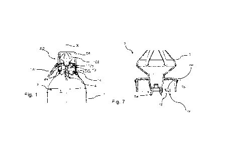
Figure 1 depicts a longitudinal cross-section of part of a priort-art
aerosol container;
Figure 2A is a side view of a non-limiting example of part of an
aerosol container according to the present invention, with an optional cap,
wherein the actuating member is in its first position;
Figure 2B is similar to Fig. 2A, showing the example without the
optional cap, wherein the actuating member is locked in its second position;
Figure 2C is similar to Figure 2B, wherein the actuating member is
operating the valve of the aerosol container;
Figure 3 depicts a perspective bottom view of part of the example of
Figures 2A-2C;
Figure 4 depicts a perspective top view of part of the example of
Figures 2A-2C;
Figure 5 shows a side view of the device part depicted in Fig. 4;
Figure 6 shows a back view of the device part depicted in Fig. 4;
Figure 7 is a cross-section over line VII-VII of Fig. 5;
Figure 8 is a cross-section over line VIII-VIII of Fig. 6;
Figure 9 depicts a perspective top view of another part of the
example of Figures 2A-2C;
Figure 10 depicts a perspective bottom view of the other part
shown in Fig. 9;
Figure 11 depicts a front view of the part shown in Fig. 9;
CA 03217770 2023- 11- 2
WO 2022/250534
PCT/NL2022/050285
7
Figure 12 depicts a top view of the part shown in Fig. 9;
Figure 13 depicts a bottom view of the part shown in Fig. 9;
Figure 14 shows a detail Q of Fig. 9;
Figure 15 shows a cross-section over line XV-XV of Figure 11;
Figure 16 shows a perspective view of a second non-limiting
embodiment of part of an aerosol container according to the present
invention, before assembly;
Figure 17 is a top view of the embodiment of Fig. 16, in assembled
condition;
Figure 18 is a side view of the embodiment of Figures 16-17;
Figure 19A is a bottom view of the assembly of Figures 16-18;
Figure 19B is a detail Y1 of Fig. 19A;
Figure 19C is a detail Y2 of Fig. 19A; and
Figure 20 shows a perspective view of two embodiments similar to
the second embodiment, the embodiment depicted on the left having the
actuating member in its first position and the embodiment depicted on the
right with the actuating member in its second position.
Figure 1 depicts an aerosol container 1 (at least an upper part
thereof) containing food product F. The container 1 has a reservoir 2
containing a propellant and a food product, and an operable discharge valve
4 or valve means, having a valve stem 4a for discharging the food product.
In particular, the valve can be located at an upper section of the container.
The present container 1 can be configured to be used upside down,
and therefore does not comprise a clip-tube dispensing mechanism. As an
example, the container 1 can be provided with operable valve means 4,
comprising a downwarclly (i.e. towards a container bottom) depressible food
product ejection stem 4a and spring means to counteract the depressing of
the stem 4a, such as in a currently marketed spray food product aerosol
container, as will be appreciated by the skilled person. For example,
depressing of the food product ejection nozzle/stem 4a leads to opening of
CA 03217770 2023- 11- 2
WO 2022/250534
PCT/NL2022/050285
8
the valve means so that food product and part of the propellant can be
ejected towards the dispensing head, to be dispensed thereby. Mentioned
spring means can urge the valve to a closed position.
Each container 1 is preferably compact (for example with an overall
volume less than 1 1), of a lightweight construction. Also for example,
initially, a packed container 1, comprising the food product, can weigh less
than 1 kg, such as about 750 or 250 g. According to an embodiment, the
container as such is made of tinplate or aluminium, coated on the inside,
and has a substantially cylindrical shape. As follows from the above, the
container can also be made of a different material, for example a rigid
plastic. Also, the present aerosol container 1 is of a non-refillable type, to
be
discarded after being used up. The present container 1 is of a relatively
inexpensive, durable construction, having few components. Generally, an
upper end of the container may include a circumferential flange 18, the
circumferential flange being e.g. an integral part of a container wall
(herein,
it should be noted that the valve structure as such can provide a section of
the container wall, or be fixed to the container wall, closing off the
container
at its upper section).
The container 1 can comprise at least one reservoir 2 containing
the food product, the food product being safe for consumption, and a suitable
propellant. As a non limiting example, the aerosol container can be packed
with food product and propellant, the initial pressure in the container being
for example in the range of 7-18 atmospheres, depending on the amount of
packed food product, as will be appreciated by the skilled person. The
propellant can consist of one or more gasses acceptable from the viewpoint
of food technology, for example a gas which substantially dissolves in the
food product, a gas which substantially does not dissolve in the food product
and a combination of these gasses. Particularly, the propellant can comprise
CO2, nitrogen (N2), laughing gas (N20) or a combination of these gasses
(such as nitrogen and laughing gas). For example, 15-25 w% (weight%) of
CA 03217770 2023- 11- 2
WO 2022/250534
PCT/NL2022/050285
9
the propellant can be N2 and the remainder of the propellant (i.e. 85-75 w%)
can be N20.
At least part of the propellant can be packed separately from the
food product, for example in the case that the container is provided with
separate reservoirs, for example with a movable or flexible partition to
provide such separation (such as in European patent application EP 1 061
006 Al). For example, the container can include a first reservoir containing
the product, and a second reservoir containing the propellant (separate from
the product)
In another embodiment, the propellant and food product are
packed together, in the same reservoir, in the aerosol container (for example
in case the container is provided with a single reservoir).
In a particular embodiment, the food product comprises cream. In
that case, as will be appreciated by the skilled person, a "spray cream" that
is obtained from use of the present aerosol container 1 generally differs from
conventional whipping cream (obtained from manually or automatically
whipping common cream without using a cream propellant) to a high
degree. Also, in the case the food product comprises cream as an ingredient,
the food product can comprise various other ingredients, for example sugar,
emulsifier, stabiliser, aroma. Preferably, the cream has a fat content in the
range of about 5%-50%, for example about 40%. Another cream composition
can include a fat milk constituent (particularly cream, or common cream)
and a non-fat milk constituent (for example skimmed milk), see EP 1 061
006 Al. Generally, a cream food product can comprise at least 80 w% of one
or more milk constituents, and preferably at least circa 90 w%.
Referring to the drawings, the container can be provided with a
manually operable discharge device 103, wherein the discharge device 103
includes a coupling structure 110 for connecting the discharge device 103 to
the aerosol container 1 (e.g. to a said circumferential flange 110). In
certain
embodiments, the discharge device 103 is firmly, undetachably, attached to
CA 03217770 2023- 11- 2
WO 2022/250534
PCT/NL2022/050285
the container 1. In other preferred embodiments, the discharge means are
detachably connected to the container 1.
For example, the coupling member 110 and the container flange 18
can firmly hold each other using a clamping force, and optionally using
5 adhesive. In a further embodiment, the coupling member 110 can be made
of a resilient material, which material provides a clamping force to firmly
grip the container after assembly. Optionally, the coupling member 110 and
the container 1 are provided with one or more blocking members and/or with
a friction enhancing surface, interacting with each other to block
10 turning/rotation of the coupling member 101 with respect to the
container 1.
The discharge device 103 can also include a manually operable
actuating member 107 and a dispensing head 105. The manually operable
discharge device 103 can be configured to cooperate with the discharge valve
4 (in particular the stem 4a) of the container to discharge the food product,
via the dispensing head 105. Preferably, the dispensing head 105 and
actuating member 107 are made in one-piece, for example via a plastic
molding process (e.g. injection molding or differently).
Also, the discharge device 103 can include an optional cap 108, e.g.
covering the dispensing head 105 before use.
The manually operable discharge means (i.e. discharge mechanism)
can include a laterally extending lever 107 as actuating member, the lever
being is pivotally connected to a mounting member 103a, via a pivot axis
103d that is located at or near a front side of a mounting member 103a of
the device 103. The lever 107 provides an actuating member, configured to
be manually pressed downwardly (towards the container) for operating the
discharge valve 4, via the respective valve stem 4a. In particular, Figure 1
shows the lever 107 in an initial idle position. From this position, the lever
7
can be pressed towards the mounting member 103a, to a second position
(such that the lever 107 pivots with respect to pivot axis 103d), to operate
CA 03217770 2023- 11- 2
WO 2022/250534
PCT/NL2022/050285
11
the container valve 4 (i.e., to axially move valve stem 4a from a valve
closing
position to a valve opening
Besides, the discharge means 103 can comprise a distal product
dispensing head 105, configured to directly connect to a distal part of the
stem 4a of the container valve 4 after mounting, such, that product can flow
from the valve into the dispensing head 105. For example, after assembly,
the valve stem 4a, which part protrudes from the container 1, can reach into
a central valve receiving neck section 105a of the dispensing head, the neck
section 105a including one or more passages for passing product, received by
the neck section 105a from the valve, to a food product receiving space that
is defined within the dispensing head 105.
Figures 2A, 2B, 2C show part of an improved aerosol container 1,
in particular a container 1 having an improved discharge device 3 that can
provide improved user interaction and tamper-indication. Generally, a
difference between the example of Figures 2A, 2B, 2C and the example of
Figure 1 is that the respective actuating member 7 is (initially) movable
from a first position to a second position with respect to a respective
container coupling structure 10, the first position being an initial position
before a first use (shown in Figure 2A), and the second position being an
operating position (shown in Figures 2B and 2C) wherein the actuating
member 7 can be manually moved to operate the container valve 4 (by
moving the member 7 to a third position, shown in Fig. 2C). Moreover it is
preferred that the actuating member 7 can not be returned back to its first
position when it has been moved to its second position. Thus, the actuating
member 7 itself can provide a tamper evident feature of the aerosol
container 1.
In particular, for example, the aerosol container 1 can be provided
with a manually operable discharge device 3, wherein the discharge device 3
includes a coupling structure 10 for connecting the discharge device 3 to the
aerosol container 1, wherein the discharge device 3 includes a manually
CA 03217770 2023- 11- 2
WO 2022/250534
PCT/NL2022/050285
12
operable actuating member 7 that is positioned in said first position with
respect to the coupling structure 10 before initial use.
The actuating member 7 can integrally include or be provided with
a dispensing head 5 for dispensing food product F, wherein the dispensing
head 5 preferably extends axially opposite the valve stem 4a of the container
valve 4 to receive food product therefrom (as in the first embodiment, i.e.
via
a neck section 5a of the dispensing head).
The actuating member 7 of the discharge device 3 can be
configured in various ways, it can be manufactured by a plastic molding
process (e.g. injection molding or differently), be made in one-piece, or be
made from several parts joined/fixed together. An actuating member 7 as
such is shown in more detail in Figures 4-8.
Similarly, the coupling structure 10 of the discharge device 3 can
be configured in various ways. For example, it can be a coupling member,
manufactured by a plastic molding process (e.g. injection molding or
differently). The coupling structure 10 can e.g. be made in one-piece, or be
made from several parts joined/fixed together. A coupling structure 10 as
such is shown in more detail in Figures 9-15.
In particular, the coupling structure 10 shown in Figures 9-15 is
configured to receive the actuating member 7 shown in Figures 4-8, an
assembled state being shown in Figures 2A, 2B, 2C, 3.
As follows from the drawings, the actuating member 7 can be
movable (e.g. turned) from the first position to a second position with
respect to the coupling structure 10, the second position providing an
operating condition of the actuating member 7 for actuating a discharge
valve 4 of the container 1 to discharge food product F, in particular an
operating condition wherein the actuating member is manually movable
(e.g. depressible) with respect to the container 1 for actuating a valve stem
4a of the valve. In particular, a direction of movement of the actuating
member 7 from its first position to its second position is different from a
CA 03217770 2023- 11- 2
WO 2022/250534
PCT/NL2022/050285
13
direction of movement during valve actuation (the former movement
direction e.g. being a circumferential direction with respect to a container
center axis X and the later movement being a pivotal direction with respect
to a pivot axis P that is normal with respect to the container center axis X).
For example, the actuating member can be entirely or partly manually
movable (e.g. depressible) with respect to the container 1 for actuating a
valve stem 4a of the valve (see also e.g. the examples of Figures 16-18
wherein the actuating member as such includes a manually operable
pressing member 207a that is pivotally connected to a guided section 207b of
the actuating member).
The discharge device 3 preferably includes blocking means 10b for
preventing valve actuating movement of the actuating member 7 when the
actuating member 7 is in that first position. In particular, the actuating
member 7 may already have a cooperating connection with the valve stem
4a when the actuating member 7 is in its first position, for example via a
neck section 5a of the dispensing head that can already be positioned onto
the stein 4a of the valve. In that case, the actuating member movement
blocking means 10b can prevent valve operation. For example, the blocking
means can include an integral section 10b of the coupling structure 10 that
can connect/couple the discharge device 3 to the aerosol container 1.
According to an embodiment, a side wall 10a of the coupling
structure 10 can define (enclose) a guide space G, the actuating member 7
having a guided section 7b (e.g. a guided body 7b) that is held in the guide
space G (i.e. in the coupling structure 10). The actuating member 7 further
includes a manually operable pressing member 7a, for example a lever or
knob, extending laterally from the guided section 7b out of the coupling
structure 10. The pressing member 7a and guided section 7b of the
actuating member are preferably integrated or fixed to each other, e.g. being
made in one-piece, so that the pressing member 7a and the guided section
CA 03217770 2023- 11- 2
WO 2022/250534
PCT/NL2022/050285
14
7b move jointly (i.e. movement of the pressing member 7a leads to
movement of the guided section 7b).
The actuating member 7 can be rotatably (sliclingly) held by the
coupling structure 10 such that the actuating member 7 can be rotated from
the first position to the second position about a rotation axis X, in
particular
an axis of rotation X that is or extends in parallel with a center line X of
the
container 1 and/or in parallel with a valve stem of the discharge valve 4 of
the container 1. In particular, the coupling structure 10 and guided section
7b of the actuating member 7 can be configured to rotatably connect to each
other. One or more radially protruding locking cams 7t can be present (e.g.
being part of the guided section 7b of the actuating member 7) for
preventing axial removal of the actuating member from the coupling
structure. Further, the coupling structure 10 and guided section 7b of the
actuating member 7 can be configured to cooperate, to limit
sliding/rotational movement of the actuating member 7.
The side wall 10a of the coupling structure 10 can be a generally
circumferential wall, e.g. an upstanding sleeve or neck portion, and can
extend concentrically with respect to a center axis X of the container 1,
after
mounting. In an embodiment, the side wall 10a of the coupling structure
includes a circumferential shoulder section 10d for connecting the coupling
structure to the container 1 (e.g. to a rim 18 thereof).
According to an embodiment, the side wall 10a of the coupling
structure 10 has a first notch section 10b for receiving (and supporting) a
proximal part of the pressing member 7a when the actuating member is in
its first position (as in Figure 2A), and a second notch section 10c (e.g.
located circumferentially next to the first notch section 10b) for receiving
(and axially guiding) the same proximal part of the pressing member 7a
when the actuating member 7 is in its second and third position (as in
Figures 2B, 2C, 3). In particular, a height of the first notch section 10b
(measured in axial direction, in parallel with a container center line X) is
CA 03217770 2023- 11- 2
WO 2022/250534
PCT/NL2022/050285
such that the pressing member 7a of the actuating member 7 rests on (is
supported by) an upper edge of the side wall 10a when the pressing member
extends through that notch section 10b. In this way, the first notch section
10b of the coupling structure 10 prevents actuating movement (i.e.
5 downward movement, towards the container wall) of the actuating member
7. Still, the first notch section 10b allows rotational movement of the
actuating member 7, towards and into the second notch section 10c of the
coupling structure wall 10a.
In particular, a height of the adjoining second notch section 10c
10 (measured in axial direction, in parallel with a container center line
X) is
such that the pressing member 7a of the actuating member 7 can be
manually actuated for opening the container valve 4, i.e. to allow the
downward movement, towards the container wall, of the actuating member
7 (as follows from Figure 2C). The height of the second notch section 10c can
15 e.g. be at least twice the height of the first notch section 10b.
A circumferential width of the first notch section 10b is preferably
about the same as or slightly larger than a circumferential width of the
pressing member 7a, so that a stable support and downward movement of
the pressing member 7a can be achieved when that member is in its first
position.
A circumferential width of the second notch section 10c is
preferably slightly larger than a circumferential width of the pressing
member 7a, allowing sufficient circumferential space for guiding the
pressing member 7a between respective operating positions.
The discharge device 3 can includes retaining means for releasably
retaining the actuating member 7 in its first position. For example, a
removable (optional) cap 8 can be configured to retain the actuating member
7 in place, or onto the edge of the wall 10a of the coupling structure, and/or
to block rotational movement of the respective laterally extending pressing
member 7a. Additionally or alternatively, a top edge of the side wall 10a of
CA 03217770 2023- 11- 2
WO 2022/250534
PCT/NL2022/050285
the coupling member 10 can include a relatively small protrusion or cam
section 10e, at the first notch section 10b or between the first and second
notch sections 10b, 10c, for retaining the pressing member 7a in the first
notch section 10b e.g. together with the cap 8, or independently of a cap 8
using a relatively low retaining force. A said relatively small retaining
force
can be overcome by an operator, by moving the pressing member 7a along
the cam section 10e to the second notch section 10c, without damaging
respective discharge device components.
The discharge device 3 preferably includes locking means 7d for
locking the actuating member 7 in its operating condition, the locking
means 7d in particular preventing moving the (entire) actuating member
back from the second position to the first position. In this way, optimum
tamper evidence can be achieved. As is mentioned before, it is preferred that
the locking means 7d of the discharge device 3 can apply a mechanical
locking force to the actuating member 7 to lock that member in its second
position, wherein the locking force can not be overcome without damaging
(e.g. plastically deforming or breaking) components of the discharge device,
such as the actuating member 7 and/or the coupling structure 10.
An embodiment of the locking means 7d is shown in more detail in
Figure 3. The locking means can include a hook member 7d, for example a
hook member 7d that can snap into a respective locking position when the
actuating member 7 enters its operating position.
According to an example, the hook member 7d can being part of the
actuating member 7 (see Fig. 3), or alternatively of the coupling structure
10. Figure 3 shows the hook member 7d having entered its locking state to
lock the actuating member 7 in its operating condition, wherein the
actuating member 7 has entered its second position (from its first position).
The locking means can include a hook member locking structure
10n for receiving and retaining the hook member 7d when the actuating
member 7 is in its operating condition. The hook member 7d and locking
CA 03217770 2023- 11- 2
WO 2022/250534
PCT/NL2022/050285
17
structure 10n can be configured to cooperate to allow axial valve actuating
movement of the actuating member 7 when the actuating member 7 is in its
operating condition. For example, a locking surface of the hook member 7d
that faces the locking structure 10n, can slide in axial direction along the
locking structure 10n when the actuating member 7 is being operated. Also,
for example, the guided section 7b of the actuating member 7 can include an
axial notch section 7n for receiving the locking structure 10n of the coupling
structure 10 during such operation. In an embodiment, the hook member 7d
can be defined by the axial notch section 7n and a further circumferential
notch section 7m of the coupling structure 10 (providing an L-shaped notch
7m, 7n). The hook member 7d can e.g. be a resilient hook member 7d, that
can resiliently deform or deflect upwardly during circumferential passage of
the locking structure 10n (during movement of the actuating member 7 from
its first to its second position), to return to an initial undeformed or
undeflected state when the locking structure 10n enters the axial notch
section 7n.
When the actuating member 7 is in its second position (being
locked in that position), it can e.g. be pivoted with respect to the coupling
structure 10, to its third position, to press the stem 4a of the valve
downwarclly (in order to open the valve). The manually operable actuating
member 7 can include a pivot section 7p (see Fig. 5), for example a
protrusion, configured to define a pivot axis P with a pivot section 10p of
the
coupling structure 10 (see Fig. 14) for providing a pivotal valve actuating
movement of the actuating member 7 when that member is in its operating
condition. Said pivot sections 7p, 10p preferably engage one another when
the actuating member 7 has been moved from its first to its second position.
For example, the pivot section 7p of the actuating member 7 can be part of
said guided section 7b and can be located in the guide space G defined by
the coupling member 10.
CA 03217770 2023- 11- 2
WO 2022/250534
PCT/NL2022/050285
18
During operation, initially, before a first use (when the container
has not dispensed any product F yet), the actuating member 7 is in its first
position with respect to the coupling structure 10 (see Fig. 2A). In that
position, actuating movement (i.e. pivotal movement) of the actuating
member 7 can be blocked by the blocking means 10b (e.g. an upper edge of
the slot or notch section 10b) of the coupling structure.
In order to dispense product for the first time, any optional cap 8
can be removed, and the actuating member 7 can be turned from its first
position to its second position (shown in Fig. 2B) with respect to the
coupling
structure 10. For example, the user can manually press the pressing
member 7a sideways to turn it out of the first notch section 10b and into the
second notch section 10c of the coupling member 10. According to an
embodiment, this movement can involve overcoming a retaining force
provided by a cam section 10e of the discharge device 3 (e.g. of an edge of
the
side wall 10a of the coupling member). Also, this movement can involve
deforming or deflecting a locking hook member 7d of the discharge device 3
from an initially undeformed state.
Once the actuating member 7 enters its second position, it becomes
locked in its operating condition. For example, this can involve snapping the
hook member 7d in place, in a locking position (as in Figure 3). Preferably,
subsequent turning the actuating member 7 back to its first position is not
possible anymore when it has been locked in its second position (at least not
possible without breaking or damaging device components). For example,
the hook member 7d returns to its initial undeformed or undeflected state,
and the locking structure 10n enters the respective axial notch section 7n,
once the actuating member 7 enters its second position.
Then, the actuating member 7 can be operated by a user, manually
via the respective pressing member 7a, to discharge food product F from the
container 1, the user pivoting/tilting the actuating member 7 (and respective
dispensing head 5) to its third position (Fig. 2C).
CA 03217770 2023- 11- 2
WO 2022/250534
PCT/NL2022/050285
19
It follows that the user operable pressing member (e.g. handle) 7a
is only possible to take in use ( to activate) after it has been turned to a
proper second position with respect to a base part (i.e. coupling member) of
the discharge device 3. In this way, the rotational position of the pressing
member as such provides tamper evidence. Also, changes of auto-activation
of the discharge device 3 can be reduced, whereas the aerosol container
provides improved user handleability.
Figures 16-19 and Fig. 20 show further examples of the present
invention, which differ from the embodiment of Figures 2-15 in that the
actuating member 207 (or actuating structure) of the discharge device 203
includes a manually operable pressing member 207a, for example a lever or
knob, extending laterally from a guided section (carrier/support section)
207b, wherein the manually operable pressing member 207a is pivotally
connected to the guided section 207b, in particular via a respective pivot
connection 207p (for providing a respective pivot axis that is normal with
respect to the container center axis X). The pivot connection 207p can e.g. be
a hinge film or different type of connection. The dispensing head 205 can e.g.
be integrally connected to or be part of (e.g. made in once piece with) the
manually operable pressing member 207a. The guided section 207b of the
actuating member can e.g. include a side wall extending concentrically with
respect to a center axis of the container 1, the side wall (207b) having a
notch 207y for receiving part of the pressing member 207a. Optionally, the
guided section 207b of the actuating member can include a top wall 207x
having an aperture for receiving (embedding) a proximal part 207z of the
pressing member 207a, an inner rim of the aperture e.g. extending opposite
an outer edge of the proximal part 207z of the pressing member 207a at a
relatively small distance (e.g. about 1 mm or less). Figure 20 shows a similar
embodiment, having a slightly differently shaped actuating member 207',
with guided section 207b', top wall 207x', notch 207y' and respective
CA 03217770 2023- 11- 2
WO 2022/250534
PCT/NL2022/050285
pressing member 207a', as well as respective coupling member 210' and
dispensing head 205'.
Besides, the guided section 207b of the actuating member can be
rotatably held by (i.e. guided by) the respective coupling structure 210 of
the
5 discharge device 203, such that the respective actuating member 207 can
be
rotated with respect to the coupling structure 210 from the first position to
the second position about its rotation axis X, in particular the axis of
rotation X that extends in parallel with a center line of the container 1
and/or in parallel with a valve stem of the discharge valve 4 of the container
10 1.
The coupling structure 210 can define a guide space G', the guided
section 207b being (rotatably) held in the guide space G'.
The guided section 207b of the actuating member can be rotatably
coupled to the coupling structure 210 in various ways, e.g. via a number of
15 snap fingers 207v (e.g. three as in this embodiment, or more than
three),
protruding radially outwardly from the guided section 207b, and snapping
behind/below respective snap finger receiving section 210w (e.g. cam or rim
section) of the of the coupling structure 210 after mounting (thereby axially
locking the guided section 207b to the coupling structure 210). Said
20 respective snap finger receiving section 210w of the coupling structure
210
can e.g. extend around/along the guide space G', in particular in a
circumferential direction (i.e. concentrically around an axis of rotation of
the
guided section 207b).
The discharge device 203 can also include blocking means 210b for
preventing valve actuating movement of the actuating member 207 when
the actuating member 207 is in its first position (shown in Figures 17, 18,
19), the blocking means being e.g. configured similar as above (concerning
the first example). The blocking means 210b can e.g. include a wall, rim or
cam structure, reaching towards an opposite bottom of the pressing member
207b, for example towards a said proximal section 207z of that pressing
CA 03217770 2023- 11- 2
WO 2022/250534
PCT/NL2022/050285
21
member 207b, for the blocking downward movement of the pressing member
207b (when the actuating member 207 is in its first position), and the
blocking means 210b can be configured to allow the downward movement of
the pressing member 207b when the respective actuating member 207 has
been rotated to its second position.
Moreover, the discharge device 207 can includes locking means
207d, 210n for locking the actuating member 207 in its operating condition,
the locking means 207d in particular preventing moving the actuating
member (i.e. both its guided member 207b and pressing member 207a) back
from the second position to the first position. The locking means can include
a hook member 207d being e.g. part of the guided member 207b of the
actuating member, configured to enter a locking state to lock the guided
member 207b of the actuating member in its operating condition when the
guided member has been rotated to a respective second position from its
first position (as with the container 1 shown on the right in Figure 20).
Optionally, the locking means (e.g. hook member 207b) can be provided by
one or more of the above-mentioned snap fingers 207v (see Figures 19A,
19B, 19C). Alternatively, one or more dedicated locking means can be
provided that are separate of such snap fingers 207v.
The locking means can additionally include a locking structure
210n, being part of the coupling structure 210, for receiving and retaining
the or each hook member 207d (which e.g. can be an afore-mentioned snap
finger 207v) when the guided section 207b of the actuating member 207 has
been moved into its operating condition. The hook member locking structure
210n can e.g. include a resilient protrusion, retaining hook, barb (see Fig.
19C) or the-like, that can e.g. resiliently deform or deflect radially (e.g.
inwardly or outwardly) during circumferential passage of a hook member
207d to be locked (the passage resulting from rotation of the guided section
207b of the actuating member 207 from its first -idle- position to its second
position), to return to the depicted initial undeformed or undeflected or less
CA 03217770 2023- 11- 2
WO 2022/250534
PCT/NL2022/050285
22
deformed state once the or each hook member 207d has been received in/by
that hook member locking structure 210n. Arrow DEF in Fig. 19C indicates
a direction of resilient deflection of said a hook member locking structure
210n, and arrow PAS indicates a direction of circumferential passage of a
corresponding hook member 207d (to be locked). It is preferred that after
the of each hook member 207d has been received by the respective locking
structure 210n, rotation of the guided section 207b of the actuating member
with respect to the coupling structure is not possible anymore (i.e. the
guided section 207b is rotationally locked). In other words, it is preferred
that the locking means 207d, 210n of the discharge device 203 can apply a
mechanical locking force to the guided section 207b of the actuating member
207 to lock that section in its second position, wherein the locking force can
not be overcome without damaging (e.g. plastically deforming or breaking)
components of the discharge device 203.
Besides, in the latter, rotationally locked position of the guided
section 207b, the pressing member 207b has been moved away from the
blocking means 210b so that the pressing member can be actuated (i.e.
pivoted with respect to the guided section 207b, to move to a respective third
position) for dispensing product.
Figure 20 shows on the left the container 1, with the respective
guided section 207b' being in an initial position, providing the first
position
of its actuating member 207'. In that position, the respective blocking means
210b prevent valve actuating movement of the actuating member 207'.
Figure 20 shows on the right the container 1, with the respective
guided section 207b' being rotated with respect to the coupling member
210'to its second position, providing the second position of its actuating
member 207'. In that position, the respective blocking means 210b do not
prevent valve actuating movement of the actuating member 207', i.e. the
pressing member 207a' can be manually pivoted downwardly/inwardly with
respect to the guided section 207b' (to a respective third position) to
operate
CA 03217770 2023- 11- 2
WO 2022/250534
PCT/NL2022/050285
23
(open) the valve of the container 1. Besides, after the respective guided
section 207b' has being rotated with respect to the coupling member 210'to
its second position, that guided section 207b' can not be rotated back to its
first position (due to the locking action of the respective locking means). It
follows that in these embodiments, part of the actuating member (e.g. the
guided section 207b') can remain in its locked second position when the
other part (the manually operable pressing member 207a') is moved to its
third position.
Also, in the above embodiments, returning the pressing member 7,
207, 207' to its idle operating position (i.e. from its third position to its
second position, after a user has stopped applying manual operating action
onto the pressing member) can be achieved via spring means of the
container valve 4, the spring means counteracting the depressing of the
stem 4a (and urging the valve to its closed position) as will be clear to the
skilled person.
While the invention has been explained using exemplary
embodiments and drawings, these do not limit the scope of the invention in
any way, said scope being provided by the claims. It will be appreciated that
many variations, alternatives and extensions are possible within said scope,
as will be clear to the skilled person from the description and the drawings.
For example, the term actuating member as such can be construed broadly,
since it can concern a single component (e.g. being made in one-piece) or a
structure of several interconnected components, as will be clear to the
skilled person.
For example, the skilled person will appreciate that the locking
means for locking the actuating member in its operating condition can be
configured in various ways, and can include e.g. one or more cooperating
cam structures and/or cooperating notches (e.g. provided by one or more
hook members and respective one or more hook member locking structures,
that can be part of the coupling structure and of the actuating member),
CA 03217770 2023- 11- 2
WO 2022/250534
PCT/NL2022/050285
24
wherein such one or more cam structures and/or notches can lock together
once the actuating member has been brought into its operation condition.
CA 03217770 2023- 11- 2