Note : Les descriptions sont présentées dans la langue officielle dans laquelle elles ont été soumises.
CA 03218267 2023-10-27
[Description]
[Title of the Invention]
POSITIVE ELECTRODE SLURRY COMPOSITION, POSITIVE ELECTRODE
MANUFACTURED USING SAME, AND LITHIUM SECONDARY BATTERY
[Technical Field]
The present application claims priority to Korean Patent Application No. 10-
2021-
0187190 filed on December 24, 2021, and Korean Patent Application No. 10-2022-
0178086,
filed on December 19, 2022, the disclosures of which are incorporated herein
by reference.
The present disclosure relates to a positive electrode slurry composition, and
a
positive electrode and lithium secondary battery manufactured using the same,
and more
specifically, to a positive electrode slurry composition for forming a
positive electrode having
excellent positive electrode adhesion, and a positive electrode and lithium
secondary battery
manufactured using the same.
[Background Technology of the Invention]
As the technology development and the demand for electric vehicles and energy
storage systems (ESSs) increase, the demand for batteries as an energy source
is rapidly
increasing, and accordingly, various studies on batteries capable of meeting
various needs
have been conducted. Particularly, studies on lithium secondary batteries
which exhibit
1
Date Recue/Date Received 2023-10-27
CA 03218267 2023-10-27
excellent lifetime and cycle characteristics while having a high energy
density as a power
source for the device are being actively conducted.
As a positive electrode active material of the lithium secondary battery,
lithium
cobalt-based oxides (LCO), lithium nickel cobalt manganese-based oxides
(LNCMO), lithium
iron phosphate (LFP), and the like have been used.
Lithium iron phosphate is inexpensive because it is abundant in resources and
contains iron, which is a low-cost material. Also, since lithium iron
phosphate has low
toxicity, environmental pollution can be reduced when lithium iron phosphate
is used.
Furthermore, since lithium iron phosphate has an olivine structure, the active
material
structure can be stably maintained at a high temperature as compared to
lithium transition
metal oxides having a layered structure. Accordingly, high-temperature
stability and high-
temperature lifetime characteristics can be improved.
However, lithium iron phosphate has a problem of poor lithium mobility and low
electrical conductivity compared to lithium transition metal oxides such as
lithium nickel
cobalt manganese oxides. Accordingly, conventionally, lithium iron phosphate
has been
used after electrical conductivity is improved by coating the surface of
lithium iron phosphate
with carbon and lithium ion mobility is improved by shortening the movement
route of
lithium by reducing an average particle diameter of lithium iron phosphate.
However, as the
size of lithium iron phosphate particles is reduced, the specific surface area
increases, and
accordingly, particle agglomeration severely occurs. As a result, the
stability of a positive
electrode slurry is degraded, and coating processability is degraded. Also,
when
agglomeration occurs in a positive electrode slurry, lithium iron phosphate
and a binder are
not effectively mixed, and thus adhesion between a current collector and a
positive electrode
2
Date Recue/Date Received 2023-10-27
CA 03218267 2023-10-27
active material layer in the manufactured positive electrode (hereinafter,
referred to as
positive electrode adhesion) is degraded.
Although a dispersant is used to suppress slurry agglomeration, when the
content of
the dispersant increases, electrode resistance increases, and a region where
the dispersant is
distributed in an active material surface increases to reduce a contact area
between the active
material and a binder, and thus electrode adhesion is rather degraded.
When positive electrode adhesion is degraded, a positive electrode active
material
layer is separated in manufacture of an electrode or during charging and
discharging, and thus
battery resistance increases, and the capacity of a secondary battery
decreases.
Conventionally, to solve the above problems, a technique for improving
positive
electrode adhesion by increasing a total binder content in a positive
electrode active material
layer, by interposing an adhesive layer such as a primer coating layer having
a high binder
content between a current collector and a positive electrode active material
layer, or by
increasing a binder content at an interface between a current collector and an
active material
.. layer by mitigating binder migration by increasing a drying time during
electrode coating is
known.
However, when a binder content in an active material layer increases, there is
a
disadvantage in that the resistance characteristics and energy density per
volume of an
electrode are degraded. Also, when a drying time increases, there is a
limitation in that
manufacturing costs of an electrode and a secondary battery increase.
[Description of the Invention]
[Technical Problem]
3
Date Recue/Date Received 2023-10-27
CA 03218267 2023-10-27
The present disclosure is directed to providing a positive electrode slurry
composition
for forming a positive electrode having excellent positive electrode adhesion.
The present disclosure is also directed to providing a positive electrode
having
excellent positive electrode adhesion and a lithium secondary battery whose
resistance
characteristics are minimally degraded by including such a positive electrode.
However, the objectives of the present disclosure are not limited to the
objectives
described above, and other objectives not described above will be clearly
understood by those
skilled in the art from the following description.
[Technical Solution]
According to one embodiment of the present invention, there is provided a
positive
electrode slurry composition which includes a positive electrode active
material, a conductive
material, a binder, a dispersant, and a solvent, wherein the positive
electrode active material
includes lithium iron phosphate, the lithium iron phosphate has an average
particle diameter
D50 of 1.5 gm or more, and the dispersant is included in an amount of 0.2
parts by weight to
0.9 parts by weight with respect to 100 parts by weight of solids in the
positive electrode
slurry composition.
According to another embodiment of the present invention, there is provided a
positive electrode which includes a current collector and a positive electrode
active material
layer disposed on the current collector, wherein the positive electrode active
material layer
includes a positive electrode active material, a conductive material, a
binder, and a dispersant,
4
Date Recue/Date Received 2023-10-27
CA 03218267 2023-10-27
the positive electrode active material includes lithium iron phosphate, the
lithium iron
phosphate has an average particle diameter Dso of 1.5 gm or more, and the
dispersant is
included in an amount of 0.2 wt% to 0.9 wt% in the positive electrode active
material layer.
According to still another embodiment of the present invention, there is
provided a
lithium secondary battery which includes a positive electrode, a negative
electrode, a
separator, and an electrolyte, wherein the positive electrode includes a
positive electrode
active material, a conductive material, a binder, and a dispersant in a
positive electrode active
material layer, the positive electrode active material includes lithium iron
phosphate, the
lithium iron phosphate has an average particle diameter Dso of 1.5 gm or more,
and the
dispersant is included in an amount of 0.2 wt% to 0.9 wt% in the positive
electrode active
material layer.
[Advantageous Effects]
Since a positive electrode slurry composition according to the present
disclosure
includes lithium iron phosphate having an average particle diameter Dso of 1.5
gm or more,
particle agglomeration can be effectively prevented even with a relatively
small amount of a
conventional dispersant. Accordingly, the lithium iron phosphate and a binder
can be
present in a positive electrode active material layer while being uniformly
mixed, and thus
positive electrode adhesion can be improved.
In addition, since the content of a dispersant that does not contribute to
positive
electrode adhesion may be low, degradation of positive electrode adhesion can
be minimized.
Accordingly, the positive electrode active material layer is prevented from
being separated,
5
Date Recue/Date Received 2023-10-27
CA 03218267 2023-10-27
and thus an increase in battery resistance can be reduced, and the lifetime
characteristics of a
battery can be improved.
Additionally, when the average particle diameter of lithium iron phosphate
particles
satisfies the above-described range, adhesion to a current collector during
rolling is improved,
.. and thus electrode separation after rolling can be prevented.
In addition, as in the present disclosure, when lithium iron phosphate having
a
relatively large particle diameter is used, and the content of a dispersant is
decreased, the
distribution of the dispersant on the lithium iron phosphate particle surface
is reduced, and
thus a contact area between a binder and the lithium iron phosphate is
increased.
Accordingly, an improvement in positive electrode adhesion can be maximized.
Additionally, when the content of a dispersant is increased, an area in which
the
surface of lithium iron phosphate particles is exposed is reduced due to the
dispersant, and
thus electrochemical characteristics are degraded. However, in the present
disclosure, since
only a relatively small amount of a dispersant is included, occurrence of
detrimental
electrochemical characteristics, especially, battery resistance, can be
suppressed.
[Brief Description of the Drawings]
FIG. 1 to FIG. 4 are scanning electron microscope (SEM) images of respective
lithium iron phosphates having an average particle diameter Dso of 0.8 gm
(FIG. 1), 1.0 gm
(FIG. 2), 1.2 gm (FIG. 3), and 2.0 gm (FIG. 4), which are used in positive
electrodes
manufactured in examples and comparative examples.
FIG. 5 is an image showing that a positive electrode manufactured using a
positive
electrode slurry composition of Comparative Example 4 is partially separated
after being
6
Date Recue/Date Received 2023-10-27
CA 03218267 2023-10-27
rolled.
FIG. 6 is an SEM image of the cross section of a positive electrode of Example
2.
FIG. 7 is an SEM image of the cross section of a positive electrode of
Comparative
Example 3.
[Detailed Description]
Advantages and features of the present disclosure and methods for achieving
the
same will be apparent by the exemplary embodiments described below in detail
with
reference to the accompanying drawings. However, the present disclosure is not
limited to
the exemplary embodiments described below and may be implemented in various
different
forms. Rather, the exemplary embodiments have been provided to make the
disclosure of
the present disclosure thorough and complete and to fully inform the scope of
the present
disclosure to those of ordinary skill in the art to which the present
disclosure pertains, and the
present disclosure is defined only by the scope of the claims. Throughout the
specification,
like reference numerals denote like elements.
All terms used herein, including technical or scientific terms, should be
interpreted as
having the same meaning as commonly understood by one of ordinary skill in the
art to which
the present disclosure pertains unless otherwise defined. Therefore, terms
such as those
defined in the commonly used dictionaries are not to be interpreted in an
ideal or overly
formal sense unless explicitly defined.
Terms used herein are for describing the exemplary embodiments and are not
intended to limit the present invention. In this specification, the singular
form may include
the plural form unless specifically stated in the phrase. As used herein, the
terms/term
7
Date Recue/Date Received 2023-10-27
CA 03218267 2023-10-27
"comprises" and/or "comprising" do/does not preclude the presence or addition
of one or
more other components in addition to the stated components.
In this specification, when a component is referred to as "containing",
"including",
"comprising", or "having" another component, it is to be understood that the
component does
not exclude other components but may include other components as well, unless
specifically
stated otherwise.
In this specification, reference to "A and/or B" refers to A, B, or A and B.
In this specification, "%" refers to wt% unless clearly described otherwise.
In this specification, Dso refers to a particle diameter corresponding to a
cumulative
volume of 50% in the particle diameter distribution curve. The D50 may be
measured, for
example, by a laser diffraction method. The laser diffraction method generally
enables
measurement of a particle diameter ranging from submicrons to several mm and
may obtain a
result with high reproducibility and high resolution.
In this specification, a "specific surface area" is measured by a BET method
and may
be specifically calculated from the amount of nitrogen gas adsorbed at a
liquid nitrogen
temperature (77 K) using BELSORP-mini II commercially available from BEL
Japan.
In this specification a "weight-average molecular weight (Mw)" refers to a
conversion value with respect to standard polystyrene measured through gel
permeation
chromatography (GPC). Specifically, the weight-average molecular weight is a
value
obtained by converting a value measured under the following conditions using
GPC, and
standard polystyrene of an Agilent system is used to make a calibration curve.
<Measurement conditions>
Analyzer: Agilent GPC (Agilent 1200 series, US)
8
Date Recue/Date Received 2023-10-27
CA 03218267 2023-10-27
Column: two connected PL Mixed B columns
Column temperature: 40 C
Eluent: Tetrahydrofuran
Flow rate: 1.0 mL/min
Concentration: ¨ 1 mg/mL (100 jtI., injection)
In this specification, positive electrode adhesion may be measured as follows.
A
positive electrode cut into pieces having a length of 150 mm and a width of 20
mm is
prepared and attached in a lengthwise direction to a slide glass having a
length of 75 mm and
a width of 25 mm using a double-sided adhesive tape so that a positive
electrode active
material layer is placed to face the slide glass. That is, the slide glass is
attached to an area
corresponding to half of the lengthwise direction of the positive electrode.
Then, rubbing is
performed 10 times using a roller so that the double-sided adhesive tape is
unifointly attached,
thereby preparing an evaluation sample. Next, the slide glass part of the
evaluation sample
is fixed to the sample stage of a universal testing machine (UTM; LS5,
AMETEK), and the
half of the positive electrode to which the slide glass is not attached is
connected to the load
cell of the UTM. The load applied to the load cell is measured while moving
the load cell up
to 50 mm with a force at an angle of 90 and a speed of 100 mm/min. In this
case, the
minimum value of the load measured in the section of 20 mm to 40 mm during the
driving
section is obtained. This process is repeated a total of 5 times, and an
average value thereof
is determined as positive electrode adhesion (gf/20 mm) of each sample.
In this specification, positive electrode resistance may be measured as
follows. A
positive electrode including a 98 gm-thick positive electrode active material
layer is cut into
pieces having a size of 50 mm x 50 mm to prepare a sample. The resistance per
unit area
9
Date Recue/Date Received 2023-10-27
CA 03218267 2023-10-27
(10 mm x 10 mm) in the thickness direction of the positive electrode active
material layer of
the sample is measured using a positive electrode resistance analyzer (MP
tester, HIOKI), and
measurement conditions are as follows. The corresponding positive electrode is
measured 3
times by the above method, and then an average value of the three measurement
values when
the standard deviation is within 10% is determined as positive electrode
resistance.
- Current: 100 A
- Speed: low
- Voltage range: 0.5 V
- Specific resistance of positive electrode current collector: 2.82E-6-6
S2.cm for
aluminum used above
Positive electrode slurry composition
A positive electrode slurry composition according to an embodiment of the
present
invention is intended to form a positive electrode active material layer and
includes a positive
electrode active material, a conductive material, a binder, a dispersant, and
a solvent, wherein
the positive electrode active material includes lithium iron phosphate, the
lithium iron
phosphate has an average particle diameter Dso of 1.5 gm or more, and the
dispersant is
included in an amount of 0.2 parts by weight to 0.9 parts by weight with
respect to 100 parts
by weight of solids in the positive electrode slurry composition.
In the case of a conventional positive electrode using lithium iron phosphate,
agglomeration of the lithium iron phosphate occurs in preparation of a
positive electrode
slurry, and thus the coatability and electrochemical characteristics of the
positive electrode
slurry are degraded. Accordingly, the content of a dispersant in such a
conventional positive
Date Recue/Date Received 2023-10-27
CA 03218267 2023-10-27
electrode material is increased to suppress the agglomeration, but a region
where the
dispersant is distributed in the lithium iron phosphate surface is increased
to reduce a contact
area between the lithium iron phosphate and the binder, and thus electrode
adhesion is rather
degraded.
As a result of prolonged research to solve the above problems, the inventors
of the
present disclosure have found that, when lithium iron phosphate has an average
particle
diameter Dso of 1.5 gm or more, and a dispersant is included in an amount of
0.2 parts by
weight to 0.9 parts by weight with respect to 100 parts by weight of solids in
the positive
electrode slurry composition, the distribution of the dispersant on the
lithium iron phosphate
surface is reduced to increase a contact area, or at least a greater
opportunity for contact,
between the binder and the lithium iron phosphate, and accordingly, positive
electrode
adhesion is substantially improved. This will be described in detail below.
(1) Positive electrode active material
The positive electrode active material may include lithium iron phosphate.
When
the positive electrode active material includes the lithium iron phosphate,
the stability of a
positive electrode including the positive electrode active material is
substantially improved,
and thus ignition of a lithium secondary battery including the positive
electrode can be
substantially reduced.
The lithium iron phosphate may be a compound represented by the following
Chemical Formula 1.
[Chemical Formula 11
Li1+aFei_xMx(1304-b)Xb
(in Chemical Formula 1, M includes any one or two or more elements selected
from
11
Date Recue/Date Received 2023-10-27
CA 03218267 2023-10-27
the group consisting of Al, Mg, Ni, Co, Mn, Ti, Ga, Cu, V, Nb, Zr, Ce, In, Zn,
and Y, X
includes any one or two or more elements selected from the group consisting of
F, S, and N,
and a, b, and x satisfy -0.5<a<0.5, 0<b<0.1, and 0<x<0.5, respectively)
For example, the lithium iron phosphate may be LiFePat.
The lithium iron phosphate may have an average particle diameter Dso of 1.5 gm
or
more. When the average particle diameter of the lithium iron phosphate is less
than 1.5 gm,
the lithium iron phosphate is excessively agglomerated in the positive
electrode slurry
composition, requiring a large amount of dispersant to prevent agglomeration.
Accordingly,
unless a large amount of dispersant is used, the lithium iron phosphate and
the binder are not
effectively mixed, and thus the adhesion of a positive electrode is degraded.
Also, when the
content of a dispersant is increased to suppress the agglomeration, a region
where the
dispersant is distributed on the lithium iron phosphate surface is increased,
reducinga contact
area between the lithium iron phosphate and the binder, and thus positive
electrode adhesion
may be degraded. When positive electrode adhesion is degraded, resistance is
increased in a
charging/discharging process of a battery, and thus the lifetime
characteristics of the battery
are degraded.
When the average particle diameter D50 of the lithium iron phosphate is 1.5 gm
or
more, agglomeration of the lithium iron phosphate can be suppressed even when
a small
amount of a dispersant is used. Also, since a region where the dispersant is
distributed in the
lithium iron phosphate surface is reduced to increase a contact area between
the binder and
the lithium iron phosphate, positive electrode adhesion can be improved.
Accordingly, the
separation of a positive electrode active material layer is prevented when a
battery is driven,
and thus an increase in battery resistance can be suppressed, and the lifetime
characteristics of
12
Date Recue/Date Received 2023-10-27
CA 03218267 2023-10-27
a battery can be improved.
Specifically, the lithium iron phosphate may have an average particle diameter
D50 of
1.5 gm to 4.5 gm, and specifically, 1.7 gm to 3.0 gm. When the average
particle diameter
D50 of the lithium iron phosphate satisfies the above-described range,
positive electrode
adhesion is improved due to the above-described reason to prevent the
separation of a positive
electrode active material layer, and thus an increase in battery resistance
can be suppressed.
Also, an increase in battery resistance, which is caused by lithium iron
phosphate having a
large particle diameter, can be prevented.
The lithium iron phosphate may be in the form of a secondary particle. The
form of
a secondary particle refers to the form of one larger particle formed by
combining a plurality
of primary lithium iron phosphate particles in the form of a single particle.
In this case, the
combination does not simply mean agglomeration by van der Waals bonding, but
may mean
agglomeration by chemical bonding. When the lithium iron phosphate is in the
form of a
secondary particle, the above-described average particle diameter D50 of the
lithium iron
phosphate corresponds to an average particle diameter D50 of the secondary
particle.
The primary lithium iron phosphate particles may have an average particle
diameter
D50 of 50 nm to 400 nm, specifically 70 nm to 300 nm, and more specifically
100 nm to 200
nm. When the above-described range is satisfied, the movement route of lithium
ions is
shortened, and a low defect content in the crystal structure is maintained,
and thus resistance
performance can be increased.
The lithium iron phosphate may have a BET specific surface area of 5 m2/g to
20
m2/g, specifically 7 m2/g to 18 m2/g, and more specifically 9 m2/g to 16 m2/g.
The above-
described range is a low BET specific surface area range compared to typical
lithium iron
13
Date Recue/Date Received 2023-10-27
CA 03218267 2023-10-27
phosphate. When the above-described range is satisfied, agglomeration of the
lithium iron
phosphate can be effectively suppressed even in a positive electrode slurry
composition
having a relatively small amount of a dispersant.
The lithium iron phosphate may be included in an amount of 94.8 parts by
weight to
98.0 parts by weight, specifically 95.0 parts by weight to 98.0 parts by
weight, and more
specifically 95.1 parts by weight to 98.0 parts by weight with respect to 100
parts by weight
of solids in the positive electrode slurry composition. When the content of
the lithium iron
phosphate satisfies the above-described range, the energy density per
weight/volume of a
positive electrode can be increased.
The lithium iron phosphate may further have a carbon coating layer formed on
the
surface of the lithium iron phosphate. The carbon coating layer may improve
the electrical
conductivity of the lithium iron phosphate to degrade the resistance of a
positive electrode.
The carbon coating layer may be formed using at least one raw material
selected from
the group consisting of glucose, sucrose, lactose, starch, an oligosaccharide,
a
polyoligosaccharide, fructose, cellulose, a furfuryl alcohol polymer, a block
copolymer of
ethylene and ethylene oxide, a vinyl-based resin, a cellulose-based resin, a
phenolic resin, a
pitch-based resin, and a tar-based resin. Specifically, the carbon coating
layer may be
formed by disposing the raw materials on the surface of the lithium iron
phosphate and firing
the same.
(2) Dispersant
The dispersant suppresses the lithium iron phosphate from being excessively
agglomerated in the positive electrode slurry composition and allows the
lithium iron
phosphate to be effectively dispersed in the prepared positive electrode
active material layer.
14
Date Recue/Date Received 2023-10-27
CA 03218267 2023-10-27
The dispersant may include a hydrogenated nitrile-based copolymer.
Specifically,
the dispersant may be a hydrogenated nitrile-based copolymer.
Specifically, the hydrogenated nitrile-based copolymer may be a copolymer
including
a structural unit derived from an a,13-unsaturated nitrile and a structural
unit derived from a
hydrogenated conjugated diene or a copolymer including a structural unit
derived from an
a,13-unsaturated nitrile, a structural unit derived from a conjugated diene,
and a structural unit
derived from a hydrogenated conjugated diene. As the a,13-unsaturated nitrile
monomer, for
example, acrylonitrile, methacrylonitrile, and the like may be used, which may
be used alone
or in combination of two or more thereof. As the conjugated diene-based
monomer, for
example, a C4 to C6 conjugated diene-based monomer such as 1,3-butadiene,
isoprene, 2,3-
methyl butadiene, and the like may be used, which may be used alone or in
combination of
two or more thereof.
More specifically, the hydrogenated nitrile-based copolymer may be a
hydrogenated
nitrile butadiene rubber (H-NBR).
The hydrogenated nitrile butadiene rubber may have a weight-average molecular
weight of 10,000 to 400,000, specifically 20,000 to 350,000, and more
specifically 30,000 to
260,000. Since the above-described average particle diameter of the lithium
iron phosphate
is larger than the average particle diameter of conventionally used lithium
iron phosphate, it is
preferable that the weight-average molecular weight of the hydrogenated
nitrile butadiene
rubber satisfies the above-described range in view of agglomeration prevention
and effective
dispersion of the lithium iron phosphate.
The dispersant may be included in an amount of 0.2 parts by weight to 0.9
parts by
weight, specifically 0.2 parts by weight to 0.7 parts by weight, and more
specifically 0.2 parts
Date Recue/Date Received 2023-10-27
CA 03218267 2023-10-27
by weight to 0.5 parts by weight with respect to 100 parts by weight of solids
in the positive
electrode slurry composition. Since the average particle diameter D50 of the
lithium iron
phosphate is 1.5 gm or more, even when the dispersant is included in a
slightly low amount as
described above, agglomeration of the lithium iron phosphate can be
effectively suppressed.
Also, since the dispersant accounts for a small amount in the positive
electrode active material
layer, a contact area between the lithium iron phosphate and the binder can be
increased, and
thus positive electrode adhesion can be improved. Accordingly, the resistance
of a positive
electrode and the lifetime characteristics of a battery can be improved.
Particularly, when the dispersant is included in an amount of 0.2 parts by
weight to
0.7 parts by weight with respect to 100 parts by weight of solids in the
positive electrode
slurry composition, the content of the dispersant that does not contribute to
adhesion relative
to the content of the binder that directly affects adhesion is decreased, and
thus positive
electrode adhesion can be substantially improved.
When the content of the dispersant exceeds 0.9 parts by weight with respect to
100
parts by weight of solids in the positive electrode slurry composition, a
contact area between
the lithium iron phosphate and the binder is reduced due to an excessive
dispersant content,
positive electrode adhesion may be degraded. Also, when the content of the
dispersant is
less than 0.2 parts by weight with respect to 100 parts by weight of solids in
the positive
electrode slurry composition, the lithium iron phosphate and the binder are
not effectively
mixed due to excessive agglomeration of the lithium iron phosphate, and thus
positive
electrode adhesion may be degraded.
(3) Binder
The binder serves to aid in the binding of the positive electrode active
material, the
16
Date Recue/Date Received 2023-10-27
CA 03218267 2023-10-27
conductive material, and the like to one another and to a current collector.
Specific
examples thereof include polyvinylidene fluoride (PVDF), polyvinyl alcohol,
carboxymethylcellulose (CMC), starch, hydroxypropyl cellulose, regenerated
cellulose,
polyvinylpyrrolidone, polytetrafluoroethylene, polyethylene, polypropylene, an
ethylene-
propylene-diene polymer (EPDM), a sulfonated EPDM, styrene butadiene rubber,
fluoro-
rubber, various copolymers thereof, and the like, which may be used alone or
in combination
of two or more thereof.
The binder may be included in an amount of 1 part by weight to 4 parts by
weight,
specifically 1.5 parts by weight to 4 parts by weight, and more specifically 2
parts by weight
to 3.5 parts by weight with respect to 100 parts by weight of solids in the
positive electrode
slurry composition. When the content of the binder satisfies the above-
described range, a
contact area between the binder and the lithium iron phosphate is increased,
and thus excellent
positive electrode adhesion can be ensured.
(4) Conductive material
The conductive material is not particularly limited as long as it does not
cause a
chemical change in a battery and has conductivity. For example, graphite;
carbon-based
materials such as carbon black, acetylene black, Ketjen black, channel black,
furnace black,
lamp black, thermal black, and the like; conductive fibers such as carbon
fibers, metal fibers,
and the like; fluorinated carbon; metal powders such as aluminum, nickel
powders, and the
like; conductive whiskers such as zinc oxide, potassium titanate, and the
like; conductive
metal oxides such as titanium oxide and the like; and conductive materials
such as
polyphenylene derivatives and the like may be used. Specific examples of a
commercially
available conductive material include acetylene black-based products (Chevron
Chemical
17
Date Recue/Date Received 2023-10-27
CA 03218267 2023-10-27
Company), Denka black (Denim Singapore Private Limited), Gulf Oil Company
products,
Ketj en black, EC-based products (Armak Company), Vulcan XC-72 (Cabot
Company), Super
P (Timcal), and the like. Preferably, the conductive material may be carbon
nanotubes.
Since the conductive network of carbon nanotubes may mitigate a migration
phenomenon of
the binder in a drying process of the positive electrode slurry composition,
carbon nanotubes
are particularly preferred as the conductive material included in the positive
electrode slurry
composition of the present disclosure.
The conductive material may be included in an amount of 0.1 parts by weight to
3.0
parts by weight, specifically 0.2 parts by weight to 2.0 parts by weight, and
more specifically
0.6 parts by weight to 1.2 parts by weight with respect to 100 parts by weight
of solids in the
positive electrode slurry composition. When the above-described range is
satisfied, the
conductive network of a positive electrode is ensured, and thus the electrical
conductivity of
the positive electrode can be improved.
(5) Solvent
As the solvent, any solvent that is typically used in the art may be used, and
examples
thereof include dimethyl sulfoxide (DMSO), isopropyl alcohol, N-methyl-2-
pyrrolidone
(NMP), acetone, water, and the like, which may be used alone or in combination
of two or
more thereof.
Meanwhile, the positive electrode slurry composition may include solids and
the
solvent. In this case, the solids may include at least one among the positive
electrode active
material, the conductive material, the binder, and the dispersant.
According to an embodiment of the present invention, a solid content of the
composition may be 40 wt% to 75 wt%, specifically 50 wt% to 70 wt%, and more
specifically
18
Date Recue/Date Received 2023-10-27
CA 03218267 2023-10-27
55 wt% to 65 wt%. When the solid content satisfies the above-described range,
the
composition can have a slurry viscosity suitable for a slurry coating process
such as slot-die
coating.
In this case, the composition may include, with respect to 100 parts by weight
of the
solids in the positive electrode slurry composition, 0.1 parts by weight to
3.0 parts by weight
of the conductive material, 1 part by weight to 4 parts by weight of the
binder, and 0.2 parts
by weight to 0.9 parts by weight of the dispersant. When the contents of the
conductive
material, binder, and dispersant satisfies the above-described ranges,
agglomeration of the
lithium iron phosphate is suppressed, and thus positive electrode adhesion can
be substantially
improved.
Positive electrode
Next, a positive electrode according to the present disclosure will be
described.
The positive electrode includes a positive electrode current collector and a
positive
electrode active material layer positioned on at least one surface of the
positive electrode
current collector. In this case, the positive electrode active material layer
includes a positive
electrode active material, a conductive material, a binder, and a dispersant,
the positive
electrode active material includes lithium iron phosphate, the lithium iron
phosphate has an
average particle diameter D50 of 1.5 gm or more, and the dispersant is
included in an amount
of 0.2 wt% to 0.9 wt% in the positive electrode active material layer. The
positive electrode
may be formed using the above-described positive electrode slurry composition.
The
positive electrode active material, dispersant, binder, and conductive
material have been
described above.
In the case of the positive electrode according to an embodiment of the
present
19
Date Recue/Date Received 2023-10-27
CA 03218267 2023-10-27
invention, since the lithium iron phosphate has an average particle diameter
D50 of 1.5 gm or
more, and the dispersant is included in an amount of 0.2 wt% to 0.9 wt% in the
positive
electrode active material layer, adhesion is enhanced. Accordingly, even when
a separate
layer for enhancing adhesion, such as a primer coating layer or a binder layer
having a high
binder content, is not provided between the positive electrode current
collector and the
positive electrode active material layer, adhesion may be exhibited at the
same or higher
levels than that of a positive electrode provided with the separate layer.
The positive electrode current collector is not particularly limited as long
as it does
not cause a chemical change in a battery and has conductivity. For example,
copper,
stainless steel, aluminum, nickel, titanium, calcined carbon, or aluminum or
stainless steel
whose surface has been treated with carbon, nickel, titanium, silver, or the
like may be used as
the current collector.
The positive electrode current collector may have a thickness of 3 gm to 500
gm and
may have fine irregularities formed on the surface thereof to increase the
adhesion to a
.. positive electrode active material layer. For example, the positive
electrode current collector
may be used in any of various forms such as a film, a sheet, a foil, a net, a
porous material, a
foam, a non-woven fabric, and the like.
The positive electrode active material layer may be positioned on at least one
surface
of the positive electrode current collector and formed of the above-described
positive
.. electrode slurry composition.
The positive electrode may be manufactured by a typical method of
manufacturing a
positive electrode, except that the above-described positive electrode slurry
composition is
used. Specifically, the positive electrode may be manufactured by applying the
positive
Date Recue/Date Received 2023-10-27
CA 03218267 2023-10-27
electrode slurry composition onto a positive electrode current collector,
followed by drying
and rolling.
As another method, the positive electrode may be manufactured by laminating,
on a
positive electrode current collector, a film obtained by casting the positive
electrode slurry
composition on a separate support and removing it from the support.
The positive electrode according to an embodiment of the present invention may
have
excellent positive electrode adhesion. Specifically, in the positive
electrode, the positive
electrode active material layer may have enhanced adhesion to the positive
electrode current
collector. As a result, the separation of the positive electrode is prevented,
and thus the cell
resistance of a secondary battery can be lowered, the capacity and output
characteristics of a
battery can be enhanced, and defects that are generated in a manufacturing
process can be
reduced.
The positive electrode may have a positive electrode adhesion of 32 gf/20 mm
or
more, specifically 35 gf/20 mm or more, and more specifically 40 gf/20 mm to
200 gf/20 mm
as measured by a 900 peel test. This positive electrode adhesion is higher
than the positive
electrode adhesion of a conventional positive electrode using lithium iron
phosphate. The
positive electrode adhesion may be exhibited because the lithium iron
phosphate has an
average particle diameter D50 of 1.5 gm or more and the dispersant is included
in an amount
of 0.2 wt% to 0.9 wt% in the positive electrode active material layer.
In addition, the positive electrode according to an embodiment of the present
invention has a structure in which the positive electrode active material
layer directly faces
the positive electrode current collector and may not include a separate layer
for enhancing
adhesion between the positive electrode active material layer and the positive
electrode
21
Date Recue/Date Received 2023-10-27
CA 03218267 2023-10-27
current collector. Even when a separate layer such as a binding layer, an
adhesive layer, a
bonding layer, or a primer coating layer, which may be interposed to enhance
adhesion
between the positive electrode current collector and the positive electrode
active material
layer, is not included, the positive electrode according to the present
disclosure may exhibit
excellent adhesion such as interfacial adhesion between the positive electrode
current
collector and the positive electrode active material layer within the above
numerical range.
Meanwhile, the positive electrode may have a resistance per unit area of 9
S2/cm2 or
less, specifically 8 S2/cm2 or less, and more specifically 7 S2/cm2 or less,
for example, 1 S2/cm2
to 9 0/cm2. The resistance may be exhibited because agglomeration of the
lithium iron
phosphate is minimized and a small amount of the dispersant is used.
Lithium secondary battery
Next, a lithium secondary battery according to the present disclosurewill be
described.
The lithium secondary battery includes a positive electrode, a negative
electrode, a
separator interposed between the positive electrode and the negative
electrode, and an
electrolyte.
The positive electrode in the lithium secondary battery has been described
above.
For example, the positive electrode includes a positive electrode active
material, a conductive
material, a binder, and a dispersant in a positive electrode active material
layer, the positive
electrode active material includes lithium iron phosphate, the lithium iron
phosphate has an
average particle diameter D50 of 1.5 gm or more, and the dispersant is
included in an amount
of 0.2 wt% to 0.9 wt% in the positive electrode active material layer.
The negative electrode may be manufactured, for example, by preparing a
composition for forming a negative electrode, which includes a negative
electrode active
22
Date Recue/Date Received 2023-10-27
CA 03218267 2023-10-27
material, a negative electrode binder, and a negative electrode conductive
material, and then
applying the composition onto a negative electrode current collector.
The negative electrode active material is not particularly limited, and any
compound
capable of reversibly intercalating and deintercalating lithium may be used.
Specific
examples thereof include: carbonaceous materials such as artificial graphite,
natural graphite,
graphitized carbon fiber, amorphous carbon, high-crystallinity carbon, and the
like;
(semi)metal-based materials capable of alloying with lithium, such as Si, Al,
Sn, Pb, Zn, Bi,
In, Mg, Ga, Cd, a Si alloy, a Sn alloy, an Al alloy, and the like; and
composites including
(semi)metal-based materials and carbonaceous materials. Examples of low-
crystallinity
carbon include soft carbon and hard carbon, and examples of the high-
crystallinity carbon
include natural graphite, Kish graphite, pyrolytic carbon, mesophase pitch-
based carbon fiber,
meso-carbon microbeads, mesophase pitches, and high-temperature calcined
carbon such as
petroleum or coal tar pitch-derived cokes, which may be used alone or in
combination of two
or more thereof. Also, as the negative electrode active material, a lithium
metal thin film
.. may be used.
The negative electrode conductive material is used to impart conductivity to
the
electrode, and any conductive material that does not cause a chemical change
in a battery and
has conductivity may be used without particular limitation. Specific examples
thereof
include graphite such as natural graphite, artificial graphite, and the like;
carbon-based
.. materials such as carbon black, acetylene black, Ketjen black, channel
black, furnace black,
lamp black, thermal black, carbon fiber, carbon nanotubes, and the like;
powders or fibers of
metals such as copper, nickel, aluminum, silver, and the like; conductive
whiskers such as
zinc oxide, potassium titanate, and the like; conductive metal oxides such as
titanium oxide
23
Date Recue/Date Received 2023-10-27
CA 03218267 2023-10-27
and the like; and conductive polymers such as polyphenylene derivatives and
the like, which
may be used alone or in combination of two or more thereof. The negative
electrode
conductive material may be typically included in an amount of 1 to 30 wt%,
preferably 1 to
20 wt%, and more preferably 1 to 10 wt% with respect to the total weight of a
negative
electrode active material layer.
The negative electrode binder serves to enhance the cohesion between negative
electrode active material particles and the adhesion between the negative
electrode active
material and the negative electrode current collector. Specific examples
thereof include
polyvinylidene fluoride (PVDF), a vinylidene fluoride-hexafluoropropylene
copolymer
.. (PVDF-co-HFP), polyvinyl alcohol, polyacrylonitrile, carboxymethylcellulose
(CMC), starch,
hydroxypropyl cellulose, regenerated cellulose, polyvinylpyrrolidone,
polytetrafluoroethylene,
polyethylene, polypropylene, ethylene-propylene-diene monomer rubber (EPDM
rubber), a
sulfonated EPDM, styrene butadiene rubber (SBR), fluoro-rubber, and various
copolymers
thereof, which may be used alone or in combination of two or more thereof. The
negative
.. electrode binder may be included in an amount of 1 wt% to 30 wt%,
preferably 1 wt% to 20
wt%, and more preferably 1 wt% to 10 wt% with respect to the total weight of a
negative
electrode active material layer.
Meanwhile, the negative electrode current collector is not particularly
limited as long
as it does not cause a chemical change in a battery and has high conductivity.
For example,
copper, stainless steel, aluminum, nickel, titanium, calcined carbon, or
copper or stainless
steel whose surface has been treated with carbon, nickel, titanium, silver, or
the like, an
aluminum-cadmium alloy, or the like may be used as the negative electrode
current collector.
In addition, the negative electrode current collector may typically have a
thickness of
24
Date Recue/Date Received 2023-10-27
CA 03218267 2023-10-27
3 gm to 500 gm. Like the positive electrode current collector, the negative
electrode current
collector may have fine irregularities formed on the surface thereof to
increase the adhesion of
a negative electrode active material. For example, the negative electrode
current collector
may be used in any of various forms such as a film, a sheet, a foil, a net, a
porous material, a
foam, a non-woven fabric, and the like.
Meanwhile, as the separator in the lithium secondary battery, any separator
that is
typically used as a separator in a lithium secondary battery may be used
without particular
limitation, and in particular, a separator that exhibits low resistance to the
migration of
electrolyte ions and has an excellent electrolyte impregnation ability is
preferred.
Specifically, a porous polymer film, for example, a porous polymer film made
of a polyolefin-
based polymer such as an ethylene homopolymer, a propylene homopolymer, an
ethylene/butene copolymer, an ethylene/hexene copolymer, an
ethylene/methacrylate
copolymer, or the like or a stacked structure having two or more layers
thereof, may be used.
Also, a typical porous non-woven fabric, for example, a non-woven fabric made
of high-
melting-point glass fiber, polyethylene terephthalate fiber, or the like may
be used. In
addition, the separator may be a porous thin film having a pore diameter of
0.01 gm to 10 gm
and a thickness of 5 gm to 300 gm.
Meanwhile, in the lithium secondary battery, the electrolyte may include an
organic
solvent and a lithium salt, which are typically used in an electrolyte, and
they are not
particularly limited.
As the organic solvent, any solvent that may function as a medium through
which
ions involved in an electrochemical reaction of a battery can migrate may be
used without
particular limitation. Specifically, as the organic solvent, an ester-based
solvent such as
Date Recue/Date Received 2023-10-27
CA 03218267 2023-10-27
methyl acetate, ethyl acetate, y-butyrolactone, E-caprolactone, or the like;
an ether-based
solvent such as dibutyl ether, tetrahydrofuran, or the like; a ketone-based
solvent such as
cyclohexanone or the like; an aromatic hydrocarbon-based solvent such as
benzene,
fluorobenzene, or the like; or a carbonate-based solvent such as dimethyl
carbonate (DMC),
diethyl carbonate (DEC), ethyl methyl carbonate (EMC), ethylene carbonate
(EC), propylene
carbonate (PC), or the like may be used.
Among those listed above, the carbonate-based solvent is preferred, and a
mixture of
a cyclic carbonate-based compound with high ion conductivity and high
permittivity (e.g., EC,
PC, etc.) and a linear carbonate-based compound with low viscosity (e.g., EMC,
DMC, DEC,
etc.), which may increase the charging/discharging performance of a battery,
is more
preferred.
As the lithium salt, any compound that is able to provide lithium ions used in
a
lithium secondary battery may be used without particular limitation.
Specifically, as the
lithium salt, LiPF6, LiC104, LiAsF6, LiBF4, LiSbF6, LiA104, LiA1C14, LiCF3S03,
LiC4F9S03,
LiN(C2F5503)2, LiN(C2F5502)2, LiN(CF3502)2. LiC1, LiI, LiB(C204)2, or the like
may be
used. The lithium salt is preferably included at a concentration of about 0.6
mol% to 2 mol%
in the electrolyte.
In addition to the above-described electrolyte components, the electrolyte may
further
include one or more additives such as pyridine, triethylphosphite,
triethanolamine, cyclic
ether, ethylenediamine, n-glyme, hexamethyl phosphoric triamide, a
nitrobenzene derivative,
sulfur, a quinone imine dye, an N-substituted oxazolidinone, an N,N-
substituted imidazolidine,
an ethylene glycol dialkyl ether, an ammonium salt, pyrrole, 2-methoxyethanol,
aluminum
trichloride, and the like for the purpose of enhancing the lifetime
characteristics of a battery,
26
Date Recue/Date Received 2023-10-27
CA 03218267 2023-10-27
suppressing a decrease in battery capacity, enhancing the discharge capacity
of a battery, or
the like. In this case, the additives may be included in an amount of 0.1 to 5
wt% with
respect to the total weight of the electrolyte.
The lithium secondary battery according to the present disclosure may be
manufactured by interposing a separator between the positive electrode and the
negative
electrode to form an electrode assembly, placing the electrode assembly in a
cylindrical
battery case or a prismatic battery case, and injecting an electrolyte.
Alternatively, the
lithium secondary battery may be manufactured by stacking the electrode
assembly,
impregnating the same with an electrolyte, placing the resultant in a battery
case, and sealing
the battery case.
In the manufacture of the lithium secondary battery according to the present
disclosure, the electrode assembly may be dried to remove one or more organic
solvents
selected from the group consisting of N-methyl-2-pyrrolidone (NMP), acetone,
ethanol, PC,
EMC, EC, and DMC, which are used in the manufacture of the positive electrode.
When an
electrolyte having the same components as the organic solvent used in the
manufacture of the
positive electrode is used, the process of drying the electrode assembly may
be omitted.
As the battery case, any battery case that is typically used in the art may be
used, and
there is no limitation on an outer shape according to the purpose of the
battery. For example,
the outer shape of the battery case may be a cylindrical form using a can, a
prismatic form, a
pouch foil'', a coin form, or the like.
The lithium secondary battery according to the present disclosure is useful in
the
fields of portable devices such as mobile phones, laptop computers, digital
cameras, and the
like, energy storage systems (ESSs), and electric vehicles such as hybrid
electric vehicles
27
Date Recue/Date Received 2023-10-27
CA 03218267 2023-10-27
(HEVs) and the like due to stably exhibiting excellent discharge capacity,
output
characteristics, and a capacity retention rate.
Hereinafter, embodiments of the present invention will be described in further
detail
with reference to examples. However, the following examples are merely
presented to
exemplify the present invention, and the scope of the present invention is not
limited to the
following examples.
Example 1: Manufacture of positive electrode
(1) Preparation of positive electrode slurry composition
LiFePat having an average particle diameter D50 of 2 gm and a BET specific
surface
area of 11 m2/g as a positive electrode active material, carbon nanotubes
(CNTs) as a
conductive material, polyvinylidene fluoride (PVdF) as a binder, and a
hydrogenated nitrile
butadiene rubber (H-NBR) as a dispersant were added to an N-methyl pyrrolidone
solvent and
stirred to prepare a positive electrode slurry composition. The positive
electrode active
material, conductive material, binder, and dispersant in the positive
electrode slurry
composition were present in a weight ratio of 95.7:1.0:2.7:0.3, and a solid
content of the
positive electrode slurry composition was 60 wt%.
(2) Manufacture of positive electrode
The positive electrode slurry composition was applied onto a 15 gm-thick
aluminum
thin film and then vacuum-dried at 130 C for 10 hours. Afterward, rolling was
performed
so that a positive electrode active material layer had a porosity of 29% to
manufacture a
positive electrode. The positive electrode active material layer had a
thickness of 98 gm,
and the loading amount of the positive electrode active material layer was 3.6
mAh/cm2.
28
Date Recue/Date Received 2023-10-27
CA 03218267 2023-10-27
Example 2: Manufacture of positive electrode
A positive electrode was manufactured in the same manner as in Example 1,
except
that a positive electrode active material and a dispersant were mixed in a
weight ratio of
95.2:0.8.
Comparative Example 1: Manufacture of positive electrode
A positive electrode was manufactured in the same manner as in Example 1,
except
that a positive electrode active material and a dispersant were mixed in a
weight ratio of
94.65:1.35.
Comparative Example 2: Manufacture of positive electrode
A positive electrode was manufactured in the same manner as in Comparative
Example 1, except that a positive electrode active material having an average
particle
diameter Dso of 0.8 gm was used.
Comparative Example 3: Manufacture of positive electrode
A positive electrode was manufactured in the same manner as in Comparative
Example 1, except that a positive electrode active material having an average
particle
diameter Dso of 1.0 gm was used, and a positive electrode active material and
a dispersant
were mixed in a weight ratio of 95.2:0.8.
Comparative Example 4: Manufacture of positive electrode
A positive electrode was manufactured in the same manner as in Comparative
Example 1, except that a positive electrode active material having an average
particle
diameter Dso of 1.2 gm was used.
[Table 1]
Average particle Content (wt%)
29
Date Recue/Date Received 2023-10-27
CA 03218267 2023-10-27
diameter (D50) of Positive Conductive Binder
Dispersant
positive electrode electrode active material
(PVdF) (H-NBR)
active material material (CNT)
(t1m) (LiFePO4)
Example 1 2.0 95.70 1 3 0.3
Example 2 2.0 95.20 1 3 0.8
Comparative 2.0 94.65 1 3 1.35
Example 1
Comparative 0.8 94.65 1 3 1.35
Example 2
Comparative 1.0 95.2 1 3 0.8
Example 3
Comparative 1.2 94.65 1 3 1.35
Example 4
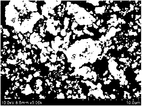
Meanwhile, FIG. 1 to FIG. 4 are scanning electron microscope (SEM) images of
respective lithium iron phosphates having an average particle diameter D50 of
0.8 gm, 1.0 gm,
1.2 gm, and 2.0 gm, which are used in the positive electrodes manufactured in
examples and
comparative examples. Specifically, FIG. 1 is an SEM image of lithium iron
phosphate
included in the positive electrode manufactured in Comparative Example 2, FIG.
2 is an SEM
image of Comparative Example 3, FIG. 3 is an SEM image of Comparative Example
4, and
FIG. 4 is an SEM image of Examples 1 and 2 and Comparative Example 1, and
lithium iron
phosphate in the positive electrode is formed in the form of a primary
particle and/or a
secondary particle.
FIG. 6 is an SEM image of the cross section of the positive electrode of
Example 2,
and FIG. 7 is an SEM image of the cross section of the positive electrode of
Comparative
Example 3. In these drawings, bright contrast indicates lithium iron
phosphate, and dark
contrast indicates that the conductive material and the binder are
agglomerated. In addition,
it is determined that, as the agglomeration region of the conductive material
is uniformly
dispersed and the area of the agglomeration region of the conductive material
is smaller, the
positive electrode active material, the conductive material, and the binder
are dispersed well.
Date Recue/Date Received 2023-10-27
CA 03218267 2023-10-27
Also, as the agglomeration region of the conductive material is closer to a
spherical shape, the
surface area of the agglomerated conductive material is minimized, and as a
result, the surface
area of the positive electrode active material, which is located adjacent to
the conductive
material and does not participate in a lithium intercalation/deintercalation
reaction, is
minimized, and thus the discharge resistance of a lithium secondary battery
may be lowered.
In the case of the positive electrode of Example 2, it can be confirmed that
the
agglomeration region of the conductive material was unifoimly dispersed as a
whole, a
deviation in the area of the agglomeration region of the conductive material
was small, and
the agglomeration region of the conductive material was close to a spherical
shape, as
compared to the positive electrode of Comparative Example 3. In the case of
the positive
electrode of Comparative Example 3, a deviation in the area of the
agglomeration region of
the conductive material was large, and several large conductive material
agglomeration
regions having a major axis length of about 10 gm were observed.
In the case of the positive electrode of Example 2, it can be confirmed that
the
positive electrode active material, the conductive material, and the binder
were dispersed well
due to a difference in the average particle diameter Dso of lithium iron
phosphate despite the
same dispersant content, as compared to the positive electrode of Comparative
Example 3.
Also, the positive electrode of Example 2 was expected to achieve excellent
discharge
resistance in a lithium secondary battery due to the agglomeration of the
conductive material
in a spherical shape, as compared to the positive electrode of Comparative
Example 3.
Experimental Example 1 ¨ Evaluation of positive electrode adhesion
Adhesion between a positive electrode active material layer and a positive
electrode
current collector in each positive electrode manufactured in Examples 1 and 2
and
31
Date Recue/Date Received 2023-10-27
CA 03218267 2023-10-27
Comparative Examples 1 to 4 was compared.
Specifically, each positive electrode manufactured in Examples 1 and 2 and
Comparative Examples 1 to 4 was cut into pieces having a length of 150 mm and
a width of
20 mm, and the positive electrode surface was attached in a lengthwise
direction to a slide
glass having a length of 75 mm and a width of 25 mm using a double-sided
adhesive tape.
That is, the slide glass was attached to an area corresponding to half of the
lengthwise
direction of the positive electrode. Then, rubbing was performed 10 times
using a roller so
that the double-sided adhesive tape was unifounly attached, thereby preparing
an evaluation
sample.
Next, the slide glass part of the evaluation sample was fixed to the sample
stage of a
universal testing machine (UTM; L55, AMETEK), and the half of the positive
electrode to
which the slide glass was not attached was connected to the load cell of the
UTM. The load
applied to the load cell was measured while moving the load cell up to 50 mm
with a force at
an angle of 90 and a speed of 100 mm/min. In this case, the minimum value of
the load
measured in the section of 20 mm to 40 mm during the driving section was
measured as the
positive electrode adhesion (gf/20 mm) of each sample. Each positive electrode
was
measured a total of 5 times, and an average value thereof is shown in Table 2
below.
Experimental Example 2 ¨ Measurement of positive electrode resistance
The resistance value of each positive electrode manufactured in Examples 1 and
2
and Comparative Examples 1 to 4 was measured and compared.
Specifically, the positive electrode including a 98 gm-thick positive
electrode active
material layer, which was manufactured in each of Examples 1 and 2 and
Comparative
Examples 1 to 4 was cut into pieces having a size of 50 mm x 50 mm. Resistance
per unit
32
Date Recue/Date Received 2023-10-27
CA 03218267 2023-10-27
area (10 mm x 10 mm) in the thickness direction of the positive electrode
active material
layer was measured using a positive electrode resistance analyzer (MP tester,
HIOKI), and
measurement conditions were as follows. Each positive electrode was measured 3
times,
and then an average value of the three measurement values when the standard
deviation is
within 10% is shown in Table 2 below.
- Current: 100 A
- Speed: low
- Voltage range: 0.5 V
- Specific resistance of positive electrode current collector: 2.82E- -6
S2.cm for
aluminum used above
Experimental Example 3 ¨ Measurement of cell resistance
(1) Manufacture of lithium secondary battery
Artificial graphite as a negative electrode active material, Super C as a
conductive
material, and SBR/CMC as a binder were mixed in a weight ratio of 96:1:3 to
prepare a
negative electrode slurry, and the slurry was applied onto one surface of a
copper current
collector, dried at 130 C, and rolled to manufacture a negative electrode.
The loading
amount of a negative electrode active material layer in the manufactured
negative electrode
was 3.6 mAh/cm2, and the negative electrode active material layer had a
porosity of 29%.
Next, an 18 m-thick polypropylene separator was interposed between the
manufactured positive electrode and negative electrode to manufacture an
electrode assembly.
The electrode assembly was accommodated in an aluminum pouch-type battery
case, 500 I
of an electrolyte in which 1.0 M LiPF6 and 2 wt% vinylene carbonate (VC) were
dissolved in
an organic solvent (EC/EMC/DMC=3:3:4 volume ratio) was injected, and the
battery case
33
Date Recue/Date Received 2023-10-27
CA 03218267 2023-10-27
was vacuum-sealed. The electrolyte was aged for a day, activated at 7.9 mAh
for 3 hours,
and then further aged for 3 days. Finally, a degassing process was performed
to manufacture
a lithium secondary battery.
(2) Measurement of cell resistance
The cell resistance value of the lithium secondary battery manufactured using
each
positive electrode of Examples 1 and 2 and Comparative Examples 1 to 4 was
measured and
compared.
Specifically, for each lithium secondary battery manufactured according to
Examples
1 and 2 and Comparative Examples 1 to 4, a value obtained by dividing a
voltage drop value
exhibited when a discharge pulse was applied at a state of charge (SOC) of 50%
and 197.5
mAh for 10 seconds by a current value was measured as cell resistance (50050
discharge
resistance).
In this case, initial cell resistance refers to a resistance value measured
after the
lithium secondary battery was manufactured, and cell resistance after 100
cycles refers to a
resistance value measured after charging and discharging were repeated 100
times under the
condition of 26.3 mAh, a range of 2.5 V to 3.6 V, and 45 C. Measurement
results are
shown in the following Table 2.
[Table 2]
Positive electrode Positive electrode
Initial cell Cell resistance after 100 cycles
Adhesion resistance resistance (me)
(gf/20 mm) (02cm2) (me)
Example 1 53 6.4 1.2 1.1
Example 2 37 7.7 1.3 1.2
Comparative 8 10.0 1.4 2.0
Example 1
Comparative not determined not determined not determined
not determined
Example 2
Comparative 30 21.7 1.4 1.8
Example 3
34
Date Recue/Date Received 2023-10-27
CA 03218267 2023-10-27
Comparative not determined not determined not determined
not determined
Example 4
Referring to Table 2, it can be confirmed that the positive electrode of
Comparative
Example 1, in which the content of a dispersant in a positive electrode active
material layer
exceeded 0.9 wt%, exhibited substantially low positive electrode adhesion and
high positive
electrode resistance compared to the positive electrodes of Examples 1 and 2.
Also, it can be
confirmed that the initial cell resistance of the lithium secondary battery
using the positive
electrode of Comparative Example 1 was higher than that of Example 1, and the
cell
resistance after 100 cycles was substantially increased compared to the
initial cell resistance.
It can be confirmed that the positive electrode of Comparative Example 3, in
which
lithium iron phosphate had an average particle diameter Dso of less than 1.5
gm, exhibited low
positive electrode adhesion and substantially high positive electrode
resistance compared to
the positive electrodes of Examples 1 and 2. Also, it can be confirmed that
the initial cell
resistance of the lithium secondary battery using the positive electrode of
Comparative
Example 3 was higher than that of Example 1, and the cell resistance after 100
cycles was
increased compared to the initial cell resistance. However, in the case of the
positive
electrode of Comparative Example 3, since a positive electrode active material
had a larger
particle size than that of Comparative Example 2, and the content of a
dispersant was lower
than that of Comparative Example 4, the separation of a positive electrode
active material
layer did not occur.
In the case of the positive electrodes of Comparative Examples 2 and 4 in
which
lithium iron phosphate had an average particle diameter Dso of less than 1.5
gm and the
content of a dispersant in a positive electrode active material layer exceeded
0.9 wt%, positive
Date Recue/Date Received 2023-10-27
CA 03218267 2023-10-27
electrode adhesion was substantially degraded, and thus the positive electrode
active material
layer of Comparative Example 2 was completely separated from a current
collector in a
rolling process, and the positive electrode active material layer of
Comparative Example 4
was partially separated from a current collector. For example, FIG. 5 is an
image showing
that the positive electrode manufactured using the positive electrode slurry
composition of
Comparative Example 4 is partially separated after being rolled, and the
positive electrode
active material layer of Comparative Example 4 was partially separated from a
current
collector as shown in FIG. 5. Therefore, the measurement of the positive
electrode adhesion,
positive electrode resistance, initial cell resistance, and cell resistance
after 100 cycles of the
positive electrodes and lithium secondary batteries of Comparative Examples 2
and 4 was not
possible.
Meanwhile, it can be confirmed that the positive electrode of Example 1
exhibited
high positive electrode adhesion and low resistance compared to the positive
electrode of
Example 2. Also, it can be confirmed that the lithium secondary battery using
the positive
.. electrode of Example 1 exhibited low initial cell resistance and low cell
resistance after 100
cycles compared to the lithium secondary battery using the positive electrode
of Example 2.
36
Date Recue/Date Received 2023-10-27