Note : Les descriptions sont présentées dans la langue officielle dans laquelle elles ont été soumises.
CA 03221982 2023-11-29
WO 2022/232618 PCT/US2022/027094
HYBRID METHOD FOR CARBON CAPTURE
CROSS-REFERENCE TO RELATED APPLICATIONS
[0001] This application claims priority to U.S. Provisional Patent
Application No.
63/182,332 filed on April 30, 2021, the disclosure of which is incorporated
herein, in its
entirety, by this reference.
BACKGROUND
[0002] Coal has been mined and used for a variety of purposes for
thousands of
years. Since the industrial revolution, the primary use for coal has been to
generate heat and
energy to power homes, industry, and transportation. Coal initially found
widespread use as a
transportation fuel for trains during the industrial revolution, but the
advent of cars and the
discovery of large petroleum deposits near the turn of the twentieth century
precipitated a
shift towards the primacy of liquid, petroleum-based fuels for transportation.
[0003] Research on coal continued, however, and the basic chemistry of
coal was
well understood by at least the early twentieth century. Although significant
research has
been conducted on coal liquefaction for more than a century, this extensive
prior work has
overwhelmingly been focused on the development of transportation fuels. The
use of coal to
produce other materials of greater industrial relevance has yet to be fully
explored. For
example, carbon-based technologies have come to the fore in recent years, with
rapid
developments being made in in the commercialization of advanced carbon
materials such as
carbon fiber, graphene, graphite, and carbon nanotubes. As these advanced
materials are
increasingly used in mass produced, high volume applications, there is a need
to quickly and
economically supply large quantities of advanced carbon materials to
manufacturers. Thus,
while transportation fuels from coal are not viewed as a fruitful avenue for
commercialization, there remains significant work to be done in developing
processes to
convert coal into the advanced carbon materials that will be instrumental in
the economy of
the future.
[0004] The use of coal as an energy source has also been historically
linked to
greenhouse gas emissions. Achieving meaningful reductions in greenhouse gas
emissions
will require a wide range of solutions, and carbon capture will play an
important role. Carbon
capture is the process by which carbon dioxide from power-plants, and other
industrial
activities that would otherwise be released into the atmosphere, is captured
and stored. The
1
CA 03221982 2023-11-29
WO 2022/232618 PCT/US2022/027094
Intergovernmental Panel on Climate Change estimates that fossil fuel power
plants and large
industrial facilities account for as much as 60 percent of global carbon
emissions. Thus, the
broad-based deployment of cost-effective carbon capture and storage would
potentially make
a massive impact on the world's greenhouse gas levels.
SUMMARY
[0005] A method of capturing carbon dioxide can include removing
carbon
dioxide from a gas. The method can include providing a gaseous feed stream
including a
carbon dioxide gas and adsorbing the carbon dioxide gas with a porous carbon
sorbent. The
method can further include de-adsorbing the carbon dioxide and combining the
carbon
dioxide with a substantially pure hydrogen gas to produce at least one of
methane and
methanol. In some embodiments, the gaseous feed stream includes at least one
of a flue gas,
an exhaust, and a furnace exhaust. The porous carbon sorbent can include a
mesoporous
structure. In some embodiments, the porous carbon sorbent includes an
activated carbon
including at least one of an activated carbon fiber, an activated charcoal, an
activated
graphene, a coal composite, and combinations thereof. In other embodiments,
the porous
carbon sorbent can include a carbon foam including an activated pitch.
[0006] In some embodiments, combining the carbon dioxide with a
substantially
pure hydrogen gas can be conducted in the presence of a catalyst. The catalyst
can include at
least one of molybdenum sulfide, ruthenium, or copper. In some embodiments,
the adsorbing
and de-adsorbing of the carbon dioxide gas can be conducted by an electric
swing adsorption.
The method of capturing carbon dioxide can also include passing the gaseous
feed stream
through a graphene-based membrane. The graphene based membrane includes at
least one of
a nanoporous single-layer graphene, a multi-layer graphene-based stacked
laminate, and a
mixed-matrix membrane.
[0007] In some embodiments, a carbon dioxide separation system can
include a
gaseous stream including carbon dioxide, an activated carbon filter, and an
adsorption
system. The activated carbon filter can include nanopores. The gaseous stream
including
carbon dioxide is configured to flow through at least a portion of the
activated carbon filter.
The activated carbon filter is configured to separate the gaseous stream into
a carbon dioxide-
rich stream and a carbon dioxide-depleted stream. In some embodiments, the
adsorption
system is configured to further separate the carbon dioxide-rich stream.
[0008] The nanopores can include a diameter from about 2 nanometers to
about 6
nanometers. In some embodiments, the adsorption system further separates the
carbon
dioxide rich stream into a substantially pure carbon dioxide stream and a
carbon dioxide-
2
CA 03221982 2023-11-29
WO 2022/232618 PCT/US2022/027094
depleted stream by electric swing adsorption. The adsorption system can
include an apparatus
including a porous dielectric adsorbent material in between and in electrical
communication
with a first electrical conductor and a second electrical conductor. In other
embodiments, the
adsorption system further separates the carbon dioxide rich stream into a
substantially pure
carbon dioxide stream and a carbon dioxide-depleted stream by physical
adsorption. The
adsorption system can further separate the carbon dioxide rich stream into a
substantially
pure carbon dioxide stream and a carbon dioxide-depleted stream by chemical
adsorption.
[0009] A method of producing carbon dioxide can include passing a
carbon
dioxide-containing gas through a graphene based membrane, preparing an
apparatus
including a porous dielectric adsorbent material in between and in electrical
communication
with a first electrical conductor and a second electrical conductor, applying
an electric field
across the porous dielectric adsorbent material, passing the carbon dioxide-
containing gas
into the porous dielectric adsorbent material, removing the electric field and
releasing the
carbon dioxide, and capturing the carbon dioxide. In some embodiments, the
carbon dioxide
couples to the first electrical conductor and the second electrical conductor.
The electric field
can include an applied voltage from about 1V to about 3V. The dielectric
adsorbent material
can include a non-conductive insulator. In some embodiments, capturing the
carbon dioxide
includes combining the carbon dioxide with a substantially pure hydrogen gas
to produce at
least one of methane and methanol.
[0010] Features from any of the disclosed embodiments can be used in
combination with one another, without limitation. In addition, other features
and advantages
of the present disclosure will become apparent to those of ordinary skill in
the art through
consideration of the following detailed description and the accompanying
drawings.
BRIEF DESCRIPTION OF THE DRAWINGS
[0011] The accompanying drawings illustrate various embodiments of the
present
apparatus and are a part of the specification. The illustrated embodiments are
merely
examples of the present apparatus and do not limit the scope thereof.
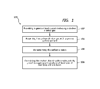
[0012] FIG. 1 illustrates a process flow diagram of a method of
removing carbon
dioxide from a gas mixture, according to an embodiment.
[0013] FIG. 2 illustrates a schematic of a porous carbon sorbent,
according to an
embodiment.
[0014] FIG. 3A illustrates a schematic view of an adsorption system
including
physical adsorption, according to an embodiment.
3
CA 03221982 2023-11-29
WO 2022/232618 PCT/US2022/027094
[0015] FIG. 3B illustrates a schematic view of an adsorption system
including
chemical adsorption, according to an embodiment.
[0016] FIG. 4 illustrates a schematic view of a graphene membrane,
according to
an embodiment.
[0017] FIG. 5A illustrates a schematic of a nanoporous graphene
membrane,
according to an embodiment.
[0018] FIG. 5B illustrates a schematic of a multi-layer graphene-based
stacked
laminate, according to an embodiment.
[0019] FIG. 5C illustrates a schematic of a mixed matrix membrane,
according to
an embodiment.
[0020] FIG. 6 illustrates a schematic of an adsorption system showing
an electric
swing adsorption, according to an embodiment.
[0021] FIG. 7 illustrates a process flow diagram of a method of
producing carbon
dioxide, according to an embodiment.
[0022] Throughout the drawings, identical reference numbers can
designate
similar, but not necessarily identical, elements.
DETAILED DESCRIPTION
[0023] The methods and systems described herein are useful in
treatment of
gaseous streams including carbon dioxide (CO2), which can be obtained in many
ways. In
particular, gaseous carbon dioxide streams include those produced by
combustion, especially
flue gas streams produced by combustion of hydrocarbon fuels. The various
aspects of the
present disclosure are described below with particular reference to such flue
gas streams, but
without intending to be limited to such streams, and can be applied to various
environments,
vehicles, buildings, and/or locations.
[0024] As used herein, "physical absorption" or "physisorption" means
absorbing
a product, in this case carbon dioxide, from a gaseous feed stream by passing
the feed stream
into a liquid which preferentially dissolves the carbon dioxide from the feed
stream,
removing the feed stream depleted of the absorbed product, and then recovering
the carbon dioxide from the liquid such as by lowering the pressure over the
liquid or by
stripping the carbon dioxide out of the liquid, wherein the absorption of
the carbon dioxide into the liquid does not involve a chemical reaction of the
carbon dioxide.
[0025] As used herein, "chemical absorption" or "chemisorption" means
absorbing a product, in this case carbon dioxide, from a gaseous feed stream
by passing the
4
CA 03221982 2023-11-29
WO 2022/232618 PCT/US2022/027094
feed stream into a liquid which contains a component with which
the carbon dioxide preferentially reacts, removing the feed stream depleted of
the absorbed
product, and then recovering the carbon dioxide from the liquid such as by
lowering the
pressure over the liquid or by stripping the carbon dioxide out of the liquid,
wherein the
absorption of the carbon dioxide into the liquid involves a chemical reaction
of
the carbon dioxide with a component in the liquid.
[0026] Reference will now be made in detail to representative
embodiments
illustrated in the accompanying drawings. It should be understood that the
following
descriptions are not intended to limit the embodiments to one preferred
embodiment. To the
contrary, it is intended to cover alternatives, modifications, and equivalents
as can be
included within the spirit and scope of the described embodiments as defined
by the
appended claims.
[0027] FIG. 1 illustrates a method 100 of removing carbon dioxide from
a gas.
The method 100 can include act 102 of providing a gaseous feed stream
including a carbon
dioxide gas and can further include a mixture of gases. In some embodiments,
the gas can
include a fluid gas stream from a power plant or industrial boiler. In other
embodiments, the
gas can include an exhaust from a vehicle or power generating machine, such as
a natural gas
or diesel generator, or a furnace exhaust. The gas can include various
components including
gases (e.g., N2, 02, NOx, SO, etc.) and particulates (e.g., fly ash). A flue
gas can typically
also include heavy metals such as mercury (Hg) that must be removed from the
flue gas prior
to being released into the atmosphere. Greenhouse gases include carbon
dioxide, methane,
nitrous oxide, and other gases that accumulate in the atmosphere and create
the heat-
reflective layer. Although carbon dioxide is not the most effective greenhouse
gas, it is
considered the largest contributor to climate change because it is so common.
[0028] The method of removing carbon dioxide from a gas includes act
104 of
adsorbing the carbon dioxide gas with a porous carbon sorbent. Adsorption can
remove one
or more components of a gaseous mixture with the help of a solid surface. The
adsorption
process can be based on significant intermolecular forces between the carbon
dioxide and the
surfaces of certain solid adsorbents such as carbon. Depending on the
temperature, pressure
and percentage of active loading, single or multiple layers of gases can be
adsorbed.
[0029] In carbon dioxide capture by adsorption technology, carbon
dioxide can be
passed through a carbon sorbent. The carbon can be porous to increase the
surface area.
Carbon dioxide is attracted towards the adsorbent and adheres on the surface
of adsorbent.
After achieving equilibrium, act 106 of desorption to get carbon dioxide in
pure form and
CA 03221982 2023-11-29
WO 2022/232618 PCT/US2022/027094
regenerated sorbent can be performed. The regenerated sorbent can be utilized
for further
cycle. Solid sorbents have the potential for significant energy savings over
liquid solvents, in
part because they avoid the need for the large quantities of water that must
be repeatedly
heated and cooled to regenerate the solvent solution. Further, adsorption
presents lower
energy requirements and avoids the shortcomings when compared to absorption.
In a post-
combustion process, adsorption is recognized to be an attractive process for
carbon dioxide
capture from flue gases, due to its lower energy requirements.
[0030] Porous carbon-based materials have high thermal and chemical
stability as
well as good adsorption capabilities. The porous carbon sorbent can include an
activated
carbon. Activated carbon can be selected as the sorbent for the method because
of some
specific characteristics that it possesses: activated carbon preferentially
adsorbs carbon
dioxide over nitrogen, is mildly water resistant, and is relatively
inexpensive. The
combination of these factors make it a prime candidate for removal and
purification of carbon
dioxide from the flue gas of a coal-fired power plant.
[0031] The formation of pores and changes to the pore structure in
activated
carbon mostly occur during the activation process. Activation occurs when the
carbon layers
are etched away through an oxidation reaction resulting in the formation of a
porous carbon
network with high surface area. As the activation temperature increases, the
raw material of
the carbon undergoes pyrolysis. The residual carbon molecules re-aggregate
into coke
structures and form numerous mesopores and/or micropores. In some embodiments,
the
porous carbon sorbent includes a mesoporous structure. A mesoporous material
is a material
containing pores with diameters between 2 and 50 nm. Pore size, pore size
distributions, and
surface area, as well as pore surface chemistry are the major factors in the
adsorption process.
Higher activation temperatures can expedite pyrolysis reactions. Moreover,
activated carbon
is stable under acidic and basic conditions.
[0032] The method of removing carbon dioxide from a gas can also
include an act
108 of combining the carbon dioxide with a substantially pure hydrogen gas to
produce at
least one of methane and methanol. A method of forming methanol by combining a
mixture
of methane, water and carbon dioxide under specific reaction conditions
sufficient to form a
mixture of hydrogen and carbon monoxide which are then reacted under
conditions sufficient
to form methanol can be achieve by various methods. U.S. Patent No. 8,440,729,
for
example, describes a conversion of carbon dioxide to methanol using bi-
reforming of
methane or natural gas, the disclosure of which is incorporated, in its
entirety, by this
reference. Carbon dioxide can be directly converted into methanol using a
homogeneous
6
CA 03221982 2023-11-29
WO 2022/232618 PCT/US2022/027094
catalyst. Jotheeswari Kothandaraman, et at. "Conversion of CO2 from Air into
Methanol
Using a Polyamine and a Homogeneous Ruthenium Catalyst." Journal of the
American
Chemical Society, the disclosure of which is incorporated, in its entirety, by
this reference. In
some embodiments, the combining of carbon dioxide with a substantially pure
hydrogen gas
can be conducted in the presence of a catalyst. The catalyst can include at
least one of
molybdenum sulfide, ruthenium, and/or copper. In other embodiments, the
captured CO2,
which is nontoxic and inexpensive, can be used to produce various organic
solvents,
chemicals, and media materials (such as calcium carbonate, glucose, and
starch), and thus it
can potentially bring substantial commercial benefits.
[0033] Referring to FIG. 2, in some embodiments, a carbon dioxide
separation
system 200 can include a gaseous stream including carbon dioxide and an
activated carbon
filter 202. The activated carbon filter 202 can include nanopores 204. The
gaseous stream
including carbon dioxide is configured to flow through at least a portion of
the activated
carbon filter 202 where the activated carbon filter 202 is configured to
separate the gaseous
stream into a carbon dioxide-rich stream and a carbon dioxide-depleted stream.
[0034] The activated carbon filter 202 can include a granular or a
powdered block
form that has been treated to be extremely porous. In some embodiments, a gram
of activated
carbon can have a surface area of 500m2 or higher. The nanopores 204 can
include a diameter
from about 2 nanometers to about 6 nanometers. The activated carbon filter 202
can include
activated carbon fiber and/or granular activated carbon. In some embodiments,
the activated
carbon filter can include a graphene-based membrane.
[0035] The activated carbon filter 202 can include a porous carbon
sorbent that
includes an activated carbon including at least one of an activated carbon
fiber, a bituminous-
coal-based activated carbon, an activated charcoal, an activated graphene, a
coal composite,
and combinations thereof. Activated carbons have a large adsorption capacity,
preferably for
small molecules (e.g. carbon dioxide). By controlling the process of
carbonization and
activation, a variety of active carbons having different porosity can be
obtained. Activated
carbons are used mainly in granular and powdered forms, but can also be
produced in textile
form by controlled carbonization and activation of textile fibers. Activated
carbon fibers
include special characteristics such as fibrous structure, high porosity, high
volumetric
capacity, excellent packing density, fast adsorption kinetics, good porous
storage capacity
and ease of handling. Activated carbon fibers (ACFs) are more advantageous
than other
forms of activated carbon, as fibers have more uniform size and shape as a
precursor to begin
with. In addition, better diffusion between the fibers makes ACFs more
suitable for
7
CA 03221982 2023-11-29
WO 2022/232618 PCT/US2022/027094
adsorption applications. U.S. Patent No. 5,446,005, for example, describes a
pitch-based
activated carbon fiber, the disclosure of which is incorporated, in its
entirety, by this
reference. Granular activated carbons (GAC) can be used primarily due to their
low cost.
The raw material for activated carbon can be any organic material with a high
char yield (i.e.
coal, peat, coconut shells, or certain polymers). Fibrous activated carbons
(ACFs) offer a
number of advantages over GACs, including greatly improved contact efficiency
with the
media leading to greater rates of adsorption, much higher surface areas (up to
2500 m2/g) and
the potential for greatly simplified in situ regeneration through electrical
resistance heating.
Activated graphene can include materials with a rigid 3D porous structure and
high specific
surface area.
[0036] In some embodiments, the activated carbon filter 202 can
include a carbon
foam. Carbon foam can be strong and lightweight, un-flammable and able to
maintain its
performance at high temperatures, and capable of absorbing carbon dioxide. In
some
embodiments, carbon foams can be produced from a variety of different
materials, including
asphalt, foamed synthetic plastic, and coal. Carbon foams constructed from a
pitch can
conduct heat well and have low density, but are comparatively weak. Coal-based
foams are
stronger and denser but do not conduct heat as well. Pitch based activated
carbons (PAC)
with a high specific surface area can be produced by a direct chemical
activation. There are
two common types of pitch that can be used for PAC production: petroleum pitch
and coal-
tar pitch. Petroleum pitch can be produced as a residue of crude oil
distillation, and coal-tar
pitch is a liquid product from the production of metallurgical coke. Because
of its
thermoplastic nature, pitch can be used for the production of all forms of
activated carbon,
including fibers, powders and granules. To produce ACFs, pitch is first melt-
spun into small-
diameter fibers. The resultant green fibers are then rendered infusible via
oxidation to prevent
them from melting and losing their shape during subsequent, higher-
temperature, heat
treatment steps.
[0037] The carbon dioxide separation system can also include an
adsorption
system 300 configured to further separate the carbon dioxide rich stream.
Referring now to
FIG. 3A, the adsorption system 300 further separates the carbon dioxide rich
stream into
a substantially pure carbon dioxide stream and a carbon dioxide-depleted
stream by physical
adsorption. The fundamental interacting force of physisorption is Van der
Waals force. In
comparison with chemisorption, in which the electronic structure of bonding
atoms or
molecules is changed and covalent or ionic bonds form, physisorption does not
result in
changes to the chemical bonding structure.
8
CA 03221982 2023-11-29
WO 2022/232618 PCT/US2022/027094
[0038] Physical adsorption can be suitable for the insoluble
adsorption process in
the adsorbent but only to the surface 302 only. Surfaces left by adsorbant 304
can be replaced
by other adsorbant (multilayer). CO2 adsorption can occur by chemical
adsorption if a
chemical reaction occurs at the exposed surface or by physical adsorption. In
physisorption
the CO2 is adsorbed weakly by the substrate itself, in chemisorption, the CO2
is adsorbed
more strongly by specific binding sites.
[0039] FIG. 3B illustrates the adsorption system 300 can further
separates the
carbon dioxide rich stream into a substantially pure carbon dioxide stream and
a carbon dioxide-depleted stream by chemical adsorption. Chemisorption is a
kind of
adsorption which involves a chemical reaction between the surface 302 and the
adsorbate 304
(e.g. CO2). New chemical bonds 306 are generated at the adsorbant surface 302.
The strong
interaction between the adsorbate 304 and the substrate surface 302 creates
new types of
electronic bonds.
[0040] In some embodiments, the adsorption system further separates
the carbon
dioxide rich stream into a substantially pure carbon dioxide stream and a
carbon dioxide-
depleted stream by electric swing adsorption. As described in detail with
reference to FIG. 6,
an adsorption system that utilizes an electric swing adsorption can be compact
and flexible,
obviates the need for ancillary equipment, and eliminates the parasitic energy
losses by using
electrochemically activated redox carriers. The adsorption system can include
an apparatus
including a porous dielectric adsorbent material in between and in electrical
communication
with a first electrical conductor and a second electrical conductor.
[0041] Referring now to FIG. 4, in some embodiments, a method 400 of
removing
carbon dioxide from a gas can include passing a gaseous feed stream 402
through a graphene-
based membrane 404. In comparison with traditional chemical separation
processes,
membrane separation is much simpler and more efficient. An ideal membrane for
molecular
separation should be as thin as possible to maximize its solvent flux, be
mechanically robust
to prevent it from fracture, and have well-defined pore sizes to guarantee its
selectivity.
Graphene is an excellent platform for developing size-selective membranes
because of its
atomic thickness, high mechanical strength, and chemical inertness. The pore
size of a
graphene based membrane can be configured to include an optimized pore size
carbon
dioxide is allowed to pass through the membrane 404 while other larger
molecules and/or
particulates are filtered. In other embodiments, such as shown in FIG. 4, the
CO2 gas can be
filtered allowing gasses 406 including smaller molecules such as N2 and H2 to
pass through
the membrane 404. The graphene-based membrane 404 can include at least one of
a
9
CA 03221982 2023-11-29
WO 2022/232618 PCT/US2022/027094
nanoporous single-layer graphene, a multi-layer graphene based stacked
laminate, and/or a
mixed-matrix membrane.
[0042] FIG. 5A illustrates a single-layer graphene. The monoatomic
thickness of
graphene-based materials gives theoretically the lowest transport resistance
possible of a
membrane. A defect-free single-layer graphene nanosheet is impermeable to gas
molecules.
To enable single-layer graphene as a membrane, there is a need to generate
nanopores of
optimized pore size for separation by a molecular sieving mechanism. There are
several
etching techniques used to generate nanopores on single-layer graphene
nanosheet to date,
including ion bombardment followed by chemical oxidation, focus-ion beam (FIB)
patterning, gold nanoparticle deposition followed by oxidation, oxygen plasma
with ozone
etching, and ultraviolet-induced oxidative treatment. Each method utilizes
etching to first
create defects on the pristine single-layer graphene which can then be
aggravated into
nanopores. There appears no systematic control over the pores sizes by using
different
techniques.
[0043] FIG. 5B illustrates a multi-layer stacked graphene membrane.
Relative to
the single-layer graphene membrane, the few- to multi-layer stacked graphene-
based
laminates, with more than one layer of nanosheet, can form a continuous film.
The
requirement on the quality and integrity of the nanosheets is, therefore, less
stringent for this
type of membrane design. Membranes with few to multi-layer stacked graphene-
based
laminates can be prepared using graphene oxide (GO) nanosheets that are
derived from the
oxidation of graphite. GO-based stacked laminates are generally fabricated
from a myriad of
techniques, such as vacuum-assisted filtration, pressure-assisted filtration,
spin-coating,
spray-coating, dip-coating, shear-alignment, and layer-by-layer techniques. GO-
based
stacked laminates can range from a thickness of 1.8 nm (-3 layers of GO
nanosheets) to
several micrometers (multi-layered). The ideal thickness of the laminates can
depend on the
gas pairs to be separated and the target applications.
[0044] FIG. 5C illustrates a mixed-matrix membrane. Mixed-matrix
membranes
are defined when a solid phase filler material is added into a continuous
matrix of polymer
phase. In this context, the graphene-based materials serve as the filler
materials. The rationale
of doing so is to utilize the key attributes of the graphene-based materials
to engineer the
transport properties of the polymer matrix. The key attributes of graphene-
based materials are
their 2D morphologies and tunable physicochemical properties. The role of
graphene-based
materials in a mixed-matrix design is slightly different from the stacked
laminates. At low
loadings, the graphene-based materials capitalize on their well-defined
interlayer spacing as
CA 03221982 2023-11-29
WO 2022/232618 PCT/US2022/027094
low resistance nanochannels for diffusion of the smaller CO2 molecules. At
high loadings,
however, the graphene-based fillers play a role that is similar to that of the
stacked laminates.
Mixed-matrix membranes are more cost-competitive as compared to graphene-based
stacked
laminates due to the smaller amount of graphene-based materials needed, as
well as greater
reliability in terms of mechanical properties and membrane performances given
that the
membranes include primarily of polymeric materials.
[0045] The adsorbing and de-adsorbing of the carbon dioxide gas can be
conducted by an electric swing adsorption. FIG. 6 illustrates an example
electrochemical cell
apparatus 600 for electric swing adsorption. When the electric swing cell
charges (e.g. current
is flowing through the cell), the carbon dioxide molecules are captured from
the gaseous feed
stream. When the electric swing cell discharges, the captured carbon dioxide
is released. In
FIG. 3, the diagram 602 shows the system being charged. The electric swing
cell can include
an apparatus including a porous dielectric adsorbent material 606 in between
and in electrical
communication with a first electrical conductor 608 and a second electrical
conductor 610.
[0046] The power source 612 creates a voltage that causes electrons to
flow from
the dielectric adsorbent material 606 to the first or second electrical
conductor 608, 610
through wires. In other words, an electric field is applied across the porous
dielectric
adsorbent material 606. The first or second electrical conductor 608,610 is
now negatively
charged. When CO2-containing air or exhaust passes into the porous dielectric
adsorbent
material 606, the first electrical conductor 608 and the second electrical
conductor 610
captures the CO2 molecules until all the active sites on its surface are
filled up. In some
embodiments, the electric field can include an applied voltage from about 1V
to about 3V.
However the electric field can be between about 0.5V to about 5V, or other
similar ranges.
[0047] The diagram 604 shows the discharge cycle. The direction of the
voltage
on the cell is reversed, and electrons flow from the first and second
electrical conductors 608,
610 back to the porous dielectric adsorbent material 606. The first and second
electrical
conductors 608, 610 are no longer negatively charged, so have no affinity for
CO2. The CO2
molecules can be released and removed out of the system/apparatus 600 by a
stream of purge
gas for subsequent use or disposal. The apparatus 600 is now regenerated and
ready to
capture more CO2. Modulating the electric field strength by adjusting the
applied voltage
during gas loading and unloading allows direct control of gas uptake and
release.
[0048] The application of the electric field across the porous
dielectric adsorbent
material 606 results in an increase in electrostatic binding forces between
the porous
dielectric adsorbent material 606 and the gas molecules within the material.
The relative
11
CA 03221982 2023-11-29
WO 2022/232618 PCT/US2022/027094
enhancement in binding is different for different gases. There is believed to
be a physical
basis for preferential binding of one gas with the porous dielectric adsorbent
material 606
compared to that for another gas. The interaction between the gas and porous
dielectric
adsorbent material 606 is believed to be strongest at localized regions of
high polarizability
that enhance gas binding at those sites in the porous dielectric adsorbent
material 606.
Binding can be enhanced through both induction and dispersion forces. The
applied field can
also enhance binding interactions among the gas molecules themselves. For
example, if the
gas is carbon dioxide, application of the electric field can enhance the
formation of carbon
dioxide clusters in the dielectric by increasing dispersion and quadrupole-
quadrupole
interactions among the CO2 molecules. When the applied electric field is
removed, the
induced electrostatic moment that stabilizes the gas dissipates. Thus, the
thermodynamic
driving force for binding can be switched on and off As a result, the
uptake/release dynamics
do not depend only on thermal diffusion because much of the energy for binding
and
releasing the gas is reversibly (or near reversibly) introduced in the form of
electrical work.
[0049] In some embodiments, the dielectric adsorbent material 606
includes a
non-conductive insulator. Carbon itself does not conduct electricity, but its
allotrope graphite
does. Most of the carbon compounds do not conduct electricity because they
have low
melting and boiling points. Nature of bonding in carbon compounds is different
from that
observed in ionic compounds, thus they are poor conductors of electricity. In
some
embodiments, a composite of carbon can be processed such that the dielectric
adsorbent
material 606, the first electrical conductor 308, the second electrical
conductor 610 include
allotropes of carbon. The composite can include a nonconductive core of carbon
with a
graphene outer surface.
[0050] The use of the electric field to adjust and enhance adsorption
provides
higher efficiency, fast cycling and response times, reduced thermal management
requirements, lower capital costs, and smaller process footprints because it
applies energy
directly to the molecules being separated, concentrated, and/or stored whereas
other current
mechanisms (pressure swing adsorption and temperature swing adsorption) apply
the
requisite energy across the bulk of the gas phase and adsorbent material. Some
energy
dissipation to heat can be expected upon executing a charge-discharge cycle,
due to dielectric
losses.
[0051] Referring now to FIG. 7, a method 700 of producing carbon
dioxide can
include an act 702 of passing a carbon dioxide-containing gas through a
graphene-based
membrane. The graphene-based membrane can be at least one of a nanoporous
single-layer
12
CA 03221982 2023-11-29
WO 2022/232618 PCT/US2022/027094
graphene, a multi-layer graphene-based stacked laminate, and a mixed-matrix
membrane, as
described above. The method of producing carbon dioxide can also include an
act 704 of
preparing an apparatus including a porous dielectric adsorbent material in
between and in
electrical communication with a first electrical conductor and a second
electrical conductor.
In some embodiments, the first electrical conductor and the second electrical
conductor can
include a carbon-based material (e.g. graphene). The method of producing
carbon dioxide can
further include an act 706 of applying an electric field across the porous
dielectric adsorbent
material and passing the carbon dioxide-containing gas into the porous
dielectric adsorbent
material, wherein the carbon dioxide couples to the first electrical conductor
and the second
electrical conductor. The method can then include an act 710 of removing the
electric field
and releasing the carbon dioxide and then an act 712 of capturing the carbon
dioxide.
[0052] In some embodiments, the electric field includes an applied
voltage from
about 1V to about 3V. The dielectric adsorbent material can include a non-
conductive
insulator. In some embodiments, the non-conductive insulator can include an
allotrope of
carbon. In other embodiments, the insulator can include air. In some
embodiments, capturing
the carbon dioxide can include combining the carbon dioxide with a
substantially pure
hydrogen gas to produce at least one methane and/or methanol.
[0053] Unless otherwise indicated, all numbers or expressions, such as
those
expressing dimensions, physical characteristics, etc., used in the
specification (other than the
claims) are understood as modified in all instances by the term "about." At
the very least, and
not as an attempt to limit the application of the doctrine of equivalents to
the claims, each
numerical parameter recited in the specification or claims which is modified
by the term
"about" should at least be construed in light of the number of recited
significant digits and by
applying ordinary rounding techniques.
[0054] In addition, all ranges disclosed herein are to be understood
to encompass
and provide support for claims that recite any and all subranges or any and
all individual
values subsumed therein. For example, a stated range of about 1 to about 10
should be
considered to include and provide support for claims that recite any and all
subranges or
individual values that are between and/or inclusive of the minimum value of 1
and the
maximum value of 10; that is, all subranges beginning with a minimum value of
1 or more
and ending with a maximum value of 10 or less (e.g., 5.5 to 10, 2.34 to 3.56,
and so forth) or
any values from 1 to 10 (e.g., 3, 5.8, 9.9994, and so forth).
[0055] The foregoing description, for purposes of explanation, used
specific
nomenclature to provide a thorough understanding of the described embodiments.
However,
13
CA 03221982 2023-11-29
WO 2022/232618 PCT/US2022/027094
it will be apparent to one skilled in the art that the specific details are
not required in order to
practice the described embodiments. Thus, the foregoing descriptions of the
specific
embodiments described herein are presented for purposes of illustration and
description. They are not target to be exhaustive or to limit the embodiments
to the precise
forms disclosed. It will be apparent to one of ordinary skill in the art that
many modifications
and variations are possible in view of the above teachings.
14