Note : Les descriptions sont présentées dans la langue officielle dans laquelle elles ont été soumises.
CA 03226748 2024-01-15
WO 2023/118883 PCT/GB2022/053364
- 1 -
CONNECTOR ASSEMBLY
The present disclosure relates to a connector assembly.
Background
It is a common requirement to connect structural members and/or components
together to form
a rigid and/or robust structure.
A traditional method of connecting posts and rails is by welding, which
provides a secure and rigid
connection. However, assembly or disassembly of a structure that is welded is
time consuming
and requires skilled labour and specialist equipment. Following disassembly,
individual
components of the structure are not easily reusable as they need to be
prepared (e.g. machined),
resulting in a loss of material and involving a large investment of time.
It is known to use fittings or couplings that connect structural members
together and allow the
structure to be disassembled and reused. A person assembling or disassembling
the structure
must handle parts of the coupling, its fixing members (e.g. a screw or bolt),
as well as the structural
members, and simultaneously hold and manipulate a tool to work the fixing
member. This can be
cumbersome, time consuming and frustrating, and can lead to an insecure
connection of the
structural members if they are not aligned properly during assembly. To reduce
error and increase
user safety, it is common for two people work together. Also the fixing
members tend to get lost
and/or damaged overtime, making re-use of the connectors frustrating.
Hence a connector which is reusable, securely connects structural members, and
allows a single
user to quickly connect and disconnect structural members is highly desirable.
Summary
According to the present disclosure there is provided an apparatus as set
forth in the appended
claims. Other features of the invention will be apparent from the dependent
claims, and the
description which follows.
CA 03226748 2024-01-15
WO 2023/118883 PCT/GB2022/053364
- 2 -
Accordingly there may be provided a connector assembly (10, 12, 14) for
engagement with a first
member (100), wherein the first member (100) defines a cavity (102) with a
contact surface (104),
and an opening (106) to the cavity (102).
The connector assembly (10, 12, 14) may comprise a core element (300) having
an outer
engagement surface (302) extending from a leading edge end (310) towards a
trailing edge end
(312). The connector assembly (10, 12, 14) may comprise an engagement sleeve
(400) extending
from a leading edge end (410) to a trailing edge end (412), the engagement
sleeve (400) defining
a passage (402) having a central axis (450), wherein the engagement sleeve
passage (402) has
an opening (406) at the trailing edge end (412). The engagement sleeve opening
(406) and
engagement sleeve passage (402) may be configured to receive at least part of
the core element
(300) extending from the leading edge end (310) of the core element (300). The
engagement
sleeve (400) may comprise an engagement member (420) having an outer surface
(422) and an
inner surface (404). The outer surface (422) of the engagement member (420)
may be configured
for engagement with the contact surface (104) of the first member (100). The
inner surface (404)
of the engagement member (420) may have a first region (452) and a second
region (454). The
second region (454) may extend from a free end (440) defined by the leading
edge end (410) to
the end of the first region (452), and the first region (452) may extend
towards the opening (406)
of the engagement sleeve passage (402). The inner surface (404) of the
engagement member
(420) and the outer engagement surface (302) of the core element (300) may be
configured to be
slideable relative to each other in the first region (452) and the second
region (454). The core
element (300) and engagement sleeve (400) may be configured such that, with
the engagement
sleeve (400) entered in the cavity (102) of the first structural member the
connector assembly (10,
12, 14) is operable to be in a first configuration in which the engagement
sleeve (400) is slideable
relative to the cavity (102) contact surface (104) of the first structural
member when the leading
edge end (310) of the core element (300) is located along the first region
(452) of the engagement
member (420). The connector assembly (10) may be operable to be in a second
configuration in
which the engagement sleeve (400) is locked relative to the first structural
member (100) when
the leading edge end (310) of the core element (300) is engaged with the
second region (454) of
the engagement member (420).
The core element (300) and engagement sleeve (400) may be configured such that
when the
leading edge end (310) of the core element (300) slides along at least part of
the second region
(454) of the inner surface (404) of the engagement member (420), the outer
surface (422) of the
engagement member (420) is urged to engage with the cavity contact surface
(104) of the first
member (100) until the connector assembly (10) is in the second configuration.
CA 03226748 2024-01-15
WO 2023/118883 PCT/GB2022/053364
- 3 -
When the leading edge end (310) of the core element (300) is located along the
first region (452)
of the inner surface (404) of the engagement member (420), a clearance fit may
be maintained
between the inner surface (404) of the engagement sleeve (400) and the outer
engagement
surface (302) of the core element (300).
When the leading edge end (310) of the core element (300) is engaged with the
second region
(454) of the inner surface (404) of the engagement member (420), there may be
an interference
fit between the inner surface (404) of the engagement sleeve (400) and the
outer engagement
surface (302) of the core element (300).
The core element (300) and engagement sleeve (400) may be configured such that
as the leading
edge end (310) of the core element (300) moves from being engaged with the
second region
(454) of the engagement member (420) to being located along the first region
(452) of the
engagement member (420), the outer engagement surface (302) of the core
element (300)
disengages with the inner engagement surface (404) of the engagement sleeve
(400) so as to
permit the engagement sleeve engagement member (420) to disengage with the
cavity contact
surface (104) of the first member (100), and such that the connector assembly
(10) transitions
from the second configuration to the first configuration to thereby allow the
engagement sleeve
(400) to slide along the cavity contact surface (104) of the first structural
member (100).
In the first configuration the free end (440) of the engagement member (420)
may be a first
distance (d1) from the central axis (450); and in the second configuration the
free end (440) of
the engagement member (420) is a second distance (d2) from the central axis
(450), the second
distance (d2) being greater than the first distance (d1).
In the first configuration the engagement member outer surface (422) may
increase in diameter
from the leading edge end (410) from a first diameter to a second diameter and
then extends
towards the trailing edge end (412) with a region (470) of constant diameter.
In the first configuration the engagement member inner surface (404) may
increase in diameter
from the leading edge end (410) along at least part of the engagement member
inner surface
(404) towards the trailing edge end (412).
CA 03226748 2024-01-15
WO 2023/118883 PCT/GB2022/053364
- 4 -
The core element (300) outer engagement surface (302) may increase in diameter
from the
leading edge end (310) towards the trailing edge end (312) terminating in a
region (370) of
constant diameter.
The core element (300) may be provided with a first locking feature (330). The
engagement sleeve
(400) may be provided with a second locking feature (430). The first locking
feature (330) and
second locking feature (430) may be configured to engage with one another to
lock the
engagement sleeve (400) and core element (300) together. The first locking
feature (330) and
second locking feature (430) may be configured to disengage from one another
so the
engagement sleeve (400) and core element (300) are separable.
The first locking feature (330) and the second locking feature (430) may be
positioned such that
before the first locking feature (330) engages with the second locking feature
(430), the leading
edge end (310) of the core element (300) is in the first region (452) of the
engagement sleeve
(400) and the connector assembly (10, 12, 14) is in the first configuration.
After the first locking
feature (330) engages with the second locking feature (430), the leading edge
end (310) of the
core element (300) may be in the second region (454) of the engagement sleeve
(400).
The engagement member outer surface (422) of the engagement sleeve (400) may
be smooth or
provided with at least one engagement tooth (424).
The core element (300) may substantially close the engagement sleeve passage
(402).
The core element (300) may define an opening (306) at the trailing edge end
(312) configured for
receiving and engaging with a second member (200).
The engagement sleeve (400) may comprise additional engagement members (420).
The
plurality of engagement members (420) may be spaced apart around the central
axis (450). Each
engagement member (420) may have an outer surface (424) for engagement with
the cavity (102)
contact surface (104), an inner surface (404) for engagement with the core
element (300) outer
surface (302) and a free end (440) at the leading edge end (410), such that
the free ends (440)
are spaced apart from one another around the central axis (450) with a slot
(408) therebetween.
CA 03226748 2024-01-15
WO 2023/118883 PCT/GB2022/053364
- 5 -
The first locking feature (330) may be provided on an outer surface of the
core element (300),
between the section of the radially outer engagement surface (302) which
engages with the
radially inner surface (404) of the engagement member (420) and the trailing
edge end (312) of
the core element (300).
The second locking feature (430) may be provided on the inner surface of the
engagement sleeve
(400), between the radially inner engagement surface (404) of the engagement
member (420)
and the trailing edge end (412) of the engagement sleeve (400).
The first locking feature (330) on the core element (300) may be a first screw
thread. The second
locking feature (430) on the engagement sleeve (400) may be a second screw
thread. Transition
from the first configuration to the second configuration starts when the first
locking feature (330)
and second locking feature (430) engage.
The engagement sleeve engagement member (420) radially inner surface (404) may
be smooth,
and the core element (300) outer engagement surface (302) may be smooth, such
that when the
leading edge end (310) of the core element (300) is in the second region (454)
of the engagement
sleeve (400), the radially inner surface (404) of the engagement member (420)
is in contact with
the core element outer engagement surface (302).
The first locking feature (330) may be provided on the outer surface (302) of
the core element
(300), and may comprise a mount (340) which extends outwards from, and extends
along, the
outer engagement surface (302) from the core element (300) leading edge (310)
towards the core
element (300) trailing edge (312), and further comprises teeth (342) provided
on a side of the
mount to extend in a first circumferential direction.
The second locking feature (430) may be provided on a side of the engagement
sleeve (400)
engagement member (420) and comprises teeth (442) which extend in a second
circumferential
direction opposite to the first circumferential direction.
The teeth (342) of the first locking feature (330) and teeth (442) of the
second locking feature
(430) may be configured for interlocking engagement such that when the teeth
(342) of the first
locking feature (330) and teeth (442) of the second locking feature (430) are
engaged, the core
element (300) and engagement sleeve (400) are locked together.
CA 03226748 2024-01-15
WO 2023/118883 PCT/GB2022/053364
- 6 -
The core element (300) and engagement sleeve (400) may be rotatable relative
to one another
around the central axis (450) to engage and disengage the first locking
feature (330) and second
locking feature (430).
There may also be provided a kit of parts for a structure comprising: a
connector assembly (10,
12, 14) as according to the present disclosure, and a first member (100) which
defines a cavity
(102) with a contact surface (104), and an opening (106) to the cavity (102)
to receive at least the
leading edge end (410) of the engagement sleeve (400).
The cavity (102) contact surface (104) for engagement with the sleeve
engagement member (420)
may be of substantially constant cross-sectional area.
The diameter of the cavity contact surface (104) for engagement with the
sleeve engagement
member (420) may at most be the same as the outer diameter of the sleeve
engagement member
outer surface (422).
The kit of parts may further comprise a second member (200); the second member
(200)
extending from and/or coupled to the core element (300), such that the first
member (100) is
coupled to the second member (200).
The first member (100) and/or second member (200) may be a post or rail.
The first member (100) may be a post and the second member (200) may be an end
cap or mount
for an accessory.
The engagement sleeve (400) may provides fluid communication between the first
member (100)
cavity (102) to an external surface of the cap.
Hence there is provided a connector assembly and a kit of parts for a
structure. The elements of
the connector assembly 10, 12, 14 may be easily assembled and combined with a
structural
member and/or accessory by one user with no need for further parts (for
example a screw) or the
use of any bonding material.
CA 03226748 2024-01-15
WO 2023/118883 PCT/GB2022/053364
- 7 -
Brief Description of the Drawings
Examples of the present disclosure will now be described with reference to the
accompanying
drawings, in which:
Figure 1 shows an exploded perspective view of a first example of a connector
assembly
according to the present disclosure;
Figures 2 to 5 show stages of assembly of the connector assembly shown in
figure 1;
Figure 6 shows a perspective view of a partial assembly of the components of
the connector
assembly shown in figures 1 to 5;
Figure 7 shows a perspective view of completed assembly of the components of
the
connector assembly shown in figures 1 to 6;
Figure 8 shows an exploded view of a second example of a connector assembly
according
to the present disclosure;
Figures 9 to 13 show stages of assembly of the connector assembly shown in
figure 8;
Figure 14 shows an exploded view of a third example of a connector assembly
according
to the present disclosure;
Figures 15 to 19 show the stages of assembly of the connector assembly shown
in
figure 14;
Figure 20 is a perspective view of the connector assembly shown in figures 14
to 19;
Figures 21 to 22 show stages of disassembly of the connector assembly shown in
figures 14 to 20;
Figure 23 shows a further example of the second example of the connector
assembly;
Figure 24 shows a further example of the third example of the connector
assembly; and
Figure 25 shows an assembly using a connector assembly according to the
present
disclosure.
Detailed Description
The present disclosure relates to a connector assembly 10, 12, 14, a kit of
parts comprising a
connector assembly 10, 12, 14 of the present disclosure and a method of
assembly of an
assembly incorporating the connector assembly 10, 12, 14 and/or a kit of parts
of the present
disclosure.
CA 03226748 2024-01-15
WO 2023/118883 PCT/GB2022/053364
- 8 -
The present disclosure relates to a connector assembly 10, 12, 14 for
engagement with a first
member 100 (i.e. a structural member) which defines a cavity 102 with a
contact surface 104, and
an opening 106 to the cavity 102, for example a hollow pipe or tube, which may
be provided as a
post or rail. The connector assembly 10, 12, 14 may be configured to engage in
the cavity defined
by the wall of a tube. The connector assembly 10, 12, 14 may be configured to
engage in an open
end of a tubular and/or structural member 100 which defines an opening to a
cavity defined by
the wall of the tubular and/or structural member 100.
As shown in the figures, the structural member 100, and/or cavity 102 may be
circular in cross-
section. In other examples the structural member 100, and/or cavity 102 may be
polygonal (for
example square) in cross-section.
The connector assembly 10, 12, 14 comprises a core element 300 and an
engagement
sleeve 400. In the examples shown these are circular in cross-section. In
other examples the
core element 300 and engagement sleeve 400 may be polygonal (for example
square) in cross-
section.
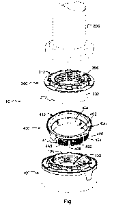
Figures 1 to 7 illustrate a first example 10 of a connector assembly according
to a present
disclosure. Figures 8 to 13 illustrate a second example 12 of a connector
assembly according to
a present disclosure. Figures 14 to 20 illustrate a third example 14 of a
connector assembly
according to a present disclosure. Although features of the different examples
10, 12, 14 vary,
they share common features. The features which are common are referenced by
use of the same
reference numerals.
In all of the examples of the present disclosure, the connector assembly 10,
12, 14 comprises a
core element 300 having an outer engagement surface 302 (e.g. a radially outer
engagement
surface 302) extending from a leading edge end 310 (e.g. leading edge end
region 310) towards
a trailing edge end 312.
The connector assembly 10, 12, 14 also comprises an engagement sleeve 400
extending from a
leading edge end 410 to a trailing edge end 412. The engagement sleeve 400
defines a
passage 402 having a central axis 450. The engagement sleeve passage 402 has
an opening 406
at the trailing edge end 412. The engagement sleeve passage 402 may have an
opening at the
leading edge end 410.
CA 03226748 2024-01-15
WO 2023/118883 PCT/GB2022/053364
- 9 -
The engagement sleeve opening 406 and engagement sleeve passage 402 are
configured to
receive at least part of the core element 300 extending from the leading edge
end 310 of the core
element 300.
The engagement sleeve 400 comprises an engagement member 420 having an outer
surface 422
(e.g. a radially outer surface 422) configured for engagement with the cavity
contact surface 104
of the first structural member 100. The engagement member 420 also comprises
an inner
surface 404 (e.g. a radially inner surface 404) for engagement with the outer
engagement
surface 302 of the core element 300. The engagement member 420 extends to a
free end 440 at
the leading edge end 410. That is to say, the engagement member 420 terminates
at a free
end 440 at the leading edge end 410.
The engagement member 420 may be termed a "leg" or "finger" as it extends from
a base part
(e.g. ring) of the engagement sleeve 400 (which defines the trailing edge end
412) to a free end
410. The engagement member 420 may be resiliently flexible. The engagement
member 420 may
be resiliently deformable. The engagement member 420 is pivotable relative to
the base part (e.g.
ring) of the engagement sleeve 400. The engagement member 420 may be flexible
(e.g.
bendable) along its length.
In some examples, for example as shown in figures 1 to 7, the outer surface
422 of the
engagement member 420 of the engagement sleeve 400 is provided with at least
one
engagement tooth 424 and is configured to press into the cavity contact
surface 104 of the first
structural member 100.
In other examples, as shown in figures 8 to 24, the outer surface 422 of the
engagement
member 420 of the engagement sleeve 400 is smooth, and is configured to press
against, but not
dig into, the cavity contact surface 104 of the first structural member 100.
In some examples, as shown in figures 8 to 24, the core element 300 may be
configured to
substantially close (and in some examples seal) the engagement sleeve passage
402. In some
examples, the core element 300 may be solid. The core element 300 may define
an opening 318
at the leading edge end 310, a passage 308 extending some, but not all, of the
way to the trailing
edge end 312.
CA 03226748 2024-01-15
WO 2023/118883 PCT/GB2022/053364
- 1 0 -
In other examples, as shown in figures 1 to 8, the core element 300 defines an
opening 306 at
the trailing edge end 312 and an opening 318 at the leading edge end 310, a
passage 1308
extending therebetween. The passage 1308 may be configured for receiving and
engaging with
a second member 200, for example a second structural member or accessory 200.
For example
the passage 1308 may be configured to mount the end of a post or to receive an
adapter which
in turn is fixed to another post.
Alternatively as shown in figure 1, the core element 300 may comprise further
engagement
features for co-operative engagement with engagement features on the second
structural
member or accessory 200. Thus the second structural member or accessory 200
may locate on
and lock to the part of the core element 300 which extends from the sleeve
400.
In the second example of connector assembly 12 shown in figures 8t0 13 and the
third example
connector assembly 14 shown in figures 14 to 22, a second structural member or
accessory 200
may be attached to the trailing edge end 312 of the core element 300. For
example the second
structural member or accessory 200 may be glued/bonded to the trailing edge
end 312, or an
engagement feature may be provided on the trailing edge end 312 for the second
structural
member or accessory 200 to be attached to. As shown in figures 23, 24 the
engagement feature
may be provided as a second core element 1300, identical to the core element
300 as herein
described, joined at their respective trailing edge ends 312, 1312 and
extending to their respective
leading edge ends 310, 1310. In such examples, the structural member or
accessory 200 is
attachable and fixable to the second core element 1300 in the same way as the
first structural
member 100 is attachable and fixable to the first core element 300.
The inner surface 404 of the engagement member 420 has a first region 452
which extends in
a direction away from the opening 406 to a second region 454, and the second
region 454
extends from the end of the first region 452 to a free end 440 defined by the
leading edge
end 410. That is to say, the second region 454 extends from the free end 440
defined by the
leading edge end 410 of the engagement member 420 to where it meets the end of
the first
region 452, and the first region 452 extends at least part of the way towards
the opening 406 of
the engagement sleeve passage 402 (i.e. towards the trailing edge end 412).
The engagement sleeve 400 comprises additional engagement members (e.g.
fingers/legs) 420
which may be of the same or similar configuration as hereinbefore described.
The plurality of
engagement members 420 may be spaced apart around central axis 450 with a slot
408
therebetween. Each engagement member 420 has an outer surface 424 (e.g. a
radially outer
CA 03226748 2024-01-15
WO 2023/118883 PCT/GB2022/053364
- 11 -
surface) for engagement with the cavity 102 contact surface 104, an inner
surface 404 (e.g.
radially inner surface) for engagement with the core element 300 outer surface
302 and a free
end 440 at the leading edge end 410. The free ends 440 may be spaced apart
from one another
around the central axis 450 with the slot 408 therebetween. The engagement
members 420 may
.. be free to move relative to one another. A clearance may be maintained
between the free ends
440.
The inner surface 404 of the engagement sleeve 400 and outer engagement
surface 302 of the
core element 300 are configured such that core element 300 is moveable (i.e.
translatable)
relative to the first region 452 and the second region 454 of the inner
surface 404 of the
engagement sleeve 400. That is to say, the outer engagement surface 302 of the
core element
300 is configured to move (i.e. translate) along the first region 452 and the
second region 454
of the inner surface 404 of the engagement sleeve 400.
The inner surface 404 each engagement sleeve engagement member 420 may be
smooth. The
outer engagement surface 302 of the core element 300 may be smooth. The outer
engagement
surface 302 of the core element 300 is configured to slide along the first
region 452 and the
second region 454 of the inner surface 404 of the engagement sleeve 400. Hence
because the
inner surface 404 of each engagement sleeve engagement member 420 and outer
engagement
surface 302 of the core element 300 are smooth, the outer engagement surface
302 of the core
element 300 may be entered into, and removed from, the engagement sleeve
passage 402, and
translate relative to the inner surface of the engagement sleeve 400,
including the inner surface
404 of each engagement sleeve engagement member 420, without the material of
one part
digging (e.g. cutting) into the material of the other part.
The features of the core element 300 and engagement sleeve 400 may be sized
relative to each
other such that a clearance fit may be maintained between the inner surface
404 of the
engagement member 420 and the outer engagement surface 302 of the core element
300 when
the leading edge end 310 of the core element 300 is located along (e.g.
adjacent) the first
region 452 of the inner surface 404 of the engagement member 420.
Hence when the leading edge end 310 of the core element 300 is in the second
region 454 of
the engagement sleeve 400, the whole of the radially inner surface 404 of each
engagement
member 402 of the engagement sleeve 400 may be in contact with co-operating
area of the core
element outer engagement surface 302.
CA 03226748 2024-01-15
WO 2023/118883 PCT/GB2022/053364
-12-
The features of the core element 300 and engagement sleeve 400 may be sized
relative to each
other such that there is an interference fit between the inner surface 404 of
the engagement
member 420, and the outer engagement surface 302 of the core element 300 when
the leading
edge end 310 of the core element 300 is engaged with the second region 454 of
the inner surface
404 of the engagement member 420.
The core element 300 and engagement sleeve 400 may be configured such that,
with the
engagement sleeve 400 entered in the cavity 102 of the first structural
member, when the
connector assembly 10, 12, 14 is in a first configuration in which the
engagement sleeve 400 is
slideable relative to the cavity 102 contact surface 104 of the first
structural member, the leading
edge end 310 of the core element 300 is located along (e.g. adjacent) the
first region 452 of the
engagement member 420. The core element 300 and engagement sleeve 400 may also
be
configured such that when the connector assembly 10, 12, 14 is in a second
configuration in
which the engagement sleeve 400 is locked relative to the first structural
member 100, the leading
edge end 310 of the core element 300 is engaged with the second region 454 of
the engagement
member 420. That is to say, the engagement sleeve 400 is freely moveable (e.g.
slideable)
relative to the cavity 102 contact surface 104 of the first structural member
until the leading edge
end 310 of the core element 300 outer surface 302 is engaged with the second
region 454 of
the engagement member 420.
The core element 300 and engagement sleeve 400 are configured such that when
the leading
edge end 310 of the core element 300 moves (e.g. slides) from the first region
452 to along at
least part of the second region 454 of the inner surface 404 of the engagement
member 420,
the outer surface 422 of the engagement member 420 is urged to engage with the
cavity contact
surface 104 of the first member 100 until the connector assembly 10, 12, 14 is
in the second
configuration.
The core element 300 and engagement sleeve 400 may be configured such when the
core
element 300 is moved in a first direction along the engagement sleeve passage
402 (e.g. parallel
to the central axis 450), the outer engagement surface 302 of the core element
300 engages with
the inner engagement surface 404 of the engagement member 420 to change the
connector
assembly 10, 12, 14 from the first configuration to the second configuration.
The first
direction is in the direction from the trailing edge end 412 to the leading
edge end 410 of the
engagement sleeve 400.
CA 03226748 2024-01-15
WO 2023/118883 PCT/GB2022/053364
- 13 -
The core element 300 and engagement sleeve 400 may be further configured such
when the core
element 300 is moved in a second direction along the engagement sleeve passage
402 (e.g.
parallel to the central axis 450), the outer engagement surface 302 of the
core element 300
disengages with the inner engagement surface 404 of the engagement sleeve 400
member to
change the connector assembly 10, 12, 14 from the second configuration to the
first
configuration to thereby allow the engagement sleeve 400 to slide along the
cavity contact
surface 104 of the first structural member 100. The second direction is in the
direction from the
leading edge end 410 to the trailing edge end 412 of the of the engagement
sleeve 400.
That is to say, the core element 300 and engagement sleeve 400 are configured
such that when
the leading edge end 310 of the core element 300 enters (i.e. starts to move
along) the second
region 454 of the engagement member 420 in the first direction, the outer
engagement surface
302 of the core element 300 is urged to engage with the inner engagement
surface 404 of
engagement member 420 such that outer surface 422 of the engagement sleeve
engagement
member 420 is urged to engage with the cavity contact surface 104 of the first
member 100.
The core element 300 and engagement sleeve 400 are configured such that when
the leading
edge end 310 of the core element 300 moves from being located along (e.g.
adjacent) the first
region 452 of the inner surface 452, to being engaged with the second region
454 of the inner
surface 404 of the engagement member 420, the outer engagement surface 302 of
the core
element 300 is urged to engage with the inner surface 404 of the engagement
member 420 such
that the outer surface 422 of the engagement member 420 is urged to engage
with the cavity
contact surface 104 of the first member 100 until the connector assembly 10,
12, 14 is in the
second configuration.
The core element 300 and engagement sleeve 400 are configured such that as the
leading edge
end region 310 of the core element 300 moves from being engaged with the
second region 454
of the engagement member 420 to being located along the first region 452 of
the engagement
member 420 (i.e. is moved in the second direction), the outer engagement
surface 302 of the
core element 300 disengages with the inner engagement surface 404 of the
engagement sleeve
400 so as to permit the engagement sleeve engagement member 420 to disengage
with the cavity
contact surface 104 of the first member 100, and such that the connector
assembly 10, 12, 14
transitions from the second configuration to the first configuration to
thereby allow the
engagement sleeve 400 to slide along the cavity contact surface 104 of the
first structural
member 100.
CA 03226748 2024-01-15
WO 2023/118883 PCT/GB2022/053364
-14-
The core element 300 outer engagement surface 302 may increase in diameter
from the leading
edge end 310 towards the trailing edge end 312, terminating in a region 370 of
constant diameter.
That is to say, the core element 300 outer engagement surface 302 has a
frustoconical region 360
extending from the leading edge end 310 to a region 370 of constant diameter,
which extends
towards the trailing edge end 312. The act of the core element 300 moving
along the inside of the
engagement sleeve 400, and in particular along the inside of the engagement
member 420,
causes the engagement member 420 to be forced away from the central axis 450.
As illustrated in figures 4, 9, 10, 11, 16, 17, in the first configuration of
the connector
assembly 10, 12, 14 the engagement member outer surface 422 has a
frustoconical region 460,
which increases in diameter from the leading edge end 410 from a first
diameter to a second
diameter. A region 470 of constant diameter extends from the second diameter
end of the
frustoconical region 460 towards the trailing edge end 412. Hence the surface
defined by the
constant diameter region 470 extends substantially parallel to the central
axis 450. The first
diameter may have a value in the range of 0.90 to 0.98 of the second diameter.
As illustrated in figures 4, 10, 11, 16, 17, in the first configuration of the
connector assembly 10
the free end 440 of the engagement member 420 is a first distance dl from the
central axis 450.
In the first configuration of the connector assembly 10, 12, 14 the distance
between the
engagement member outer surface 422 and the central axis 450 varies along the
length of the
engagement member outer surface 422.
As illustrated in figures 5, 13, 19, in the second configuration of the
connector assembly 10, 12,
14 at least part of the engagement member 420 is forced away from the central
axis 450 by the
core element 300 such that the free end 440 of the engagement member is a
second distance
d2 from the central axis 450, the second distance d2 being greater than the
first distance dl.
That is to say, in the second configuration of the connector assembly 10, 12,
14 the free end
440 of the engagement member 420 is a second distance d2 from the central axis
450, the
second distance d2 being greater than the first distance dl. The second
distance d2 may be
at least equal to the internal radius of the cavity 102 of the structural
member 100.
In the second configuration of the connector assembly 10, 12, 14, the distance
between the
engagement member outer surface 422 and the central axis 450 may be
substantially constant,
since in the second configuration the engagement member outer surface 422 is
pressed against
the contact surface 104 of the structural member 100. In the second
configuration of the
connector assembly 10, 12, 14, the distance between the engagement member
outer surface 422
CA 03226748 2024-01-15
WO 2023/118883 PCT/GB2022/053364
- 15 -
and the central axis 450 may be greatest at the free end 440 and reduce in
value along at least
part of the engagement member outer surface 422.
As illustrated in figure 9 (and applicable to the other examples) in the first
configuration the
engagement member inner surface 404 may increase in diameter from id1 to id2
from the leading
edge end 410 along at least part of the engagement member inner surface 404
towards a region
of constant diameter id3, and the region of constant diameter extends from the
id2 diameter to
the trailing edge 412.
Hence, when at least part of the core element 300 is entered and moved along
the passage 402
of the sleeve member 400, and the core element 300 outer engagement surface
302 pushes
against at least part of the engagement member inner surface 404, the
frustoconical shape of the
core element 300 outer engagement surface 302 and/or engagement member inner
surface 404
result in an interaction such that the further that the core element 300 is
pushed into the passage
402 towards the free end 440 of the engagement member 400, the free end 440 of
the
engagement member 400, and hence at least part of the engagement member outer
surface 422,
is urged away from the central axis 450. In this way, in practice, at least
part of the engagement
member outer surface 422 engages with the contact surface 104 of the
structural member 100 as
the core element 300 is pushed along the passage 402.
In each example of the connector assembly 10, 12, 14 of the present
disclosure, the core element
300 may be provided with a first locking feature 330 and/or the engagement
sleeve 400 may be
provided with a second locking feature 430. The first locking feature 330 and
second locking
feature 430 may be configured to engage with one another to lock the
engagement sleeve 400
and core element 300 together and may be configured to disengage from one
another so the
engagement sleeve 400 and core element 300 are separable (i.e. can move, for
example slide,
relative to one another so the assembly may be taken apart).
The first locking feature 330 and second locking feature 430 are positioned on
the core
element 300 and sleeve 400 respectively such that as the leading edge 310 of
the core element
300 is pushed along the first region 452 of the passage 402 of the sleeve 400
in the direction
from the trailing edge end 412 to the leading edge end 410, and before the
first locking feature
330 engages with the second locking feature 430, the connector assembly 10,
12, 14 is in the
first configuration.
CA 03226748 2024-01-15
WO 2023/118883 PCT/GB2022/053364
-16-
The first locking feature 330 and second locking feature 430 are positioned on
the core
element 300 and sleeve 400 respectively such that as and/or just after the
leading edge end 310
of the core element 300 engages with the second region 454 of the engagement
sleeve 400, the
first locking feature 330 engages with the second locking feature 430.
The transition from the connector assembly 10, 12, 14 from first configuration
to the second
configuration starts when the first locking feature 330 and second locking
feature 430 engage.
The second configuration is achieved by the act of locking first locking
feature 330 with the
second locking feature 430
In the examples shown in Figures 1 to 7 with respect to the first example
connector assembly 10
and figures 8 to 13 of the second example connector assembly 12, the first
locking feature 330 is
provided on an outer surface (e.g. radially outer surface) of the core element
300, between the
section of the radially outer engagement surface 302 which engages with the
radially inner surface
404 of the engagement member 420 and the trailing edge end 312 of the core
element 300. The
second locking feature 430 is provided on the inner surface (e.g. radially
inner surface) of the
engagement sleeve 400, between the radially inner engagement surface 404 of
the engagement
member 420 and the trailing edge end 412 of the engagement sleeve 400.
The first locking feature 330 on the core element 300 may be provided as a
first screw thread.
The second locking feature 430 on the engagement sleeve 400 may be provided as
a second
screw thread. The first screw thread and second screw thread are compatible
with one another.
The core element 300 and engagement sleeve 400 are rotatable relative to one
another around
the central axis 450 to engage and disengage the first locking feature 330 and
second locking
feature 430. The act of turning the core member 300 and sleeve member 400
relative to one
another around the central axis 450 with the locking features 330, 430 engaged
causes movement
of the core member 300 along the passage 402 of the sleeve. The screw thread
may be a four-
start thread.
When the first locking feature 330 and second locking feature 430 are engaged,
the core element
300 and sleeve member 400 are prevented from sliding relative to one another
along the central
axis 450.
In the examples shown in Figures 14 to 22 with respect to the third example
connector
assembly 14, and as best shown in Figures 20 to 22, the first locking feature
330 is provided on
CA 03226748 2024-01-15
WO 2023/118883 PCT/GB2022/053364
- 17 -
the outer surface 302 (e.g. radially outer surface) of the core element 300
and comprises a mount
340 (e.g. an extension or pedestal) which extends outwards from (e.g. radially
outward from), and
extends along the outer engagement surface 302 from the core element 300
leading edge 310
part of the way towards the core element 300 trailing edge 312. A plurality of
mounts 340 may be
provided, spaced apart around the outer engagement surface 302 of the core
element 300 leading
edge 310.
In the example shown in figures 14 to 22, in which a plurality of engagement
members 420 are
provided, spaced apart around the boundary/circumference of the sleeve 400,
the or each
mount 340 is sized to fit in the slot 408 defined between two adjacent
engagement members 420.
The outer diameter defined by the outer surface (e.g. radially outer surface)
of the mounts 340 is
no more than the diameter of the passage 402, so that the mounts 340 can pass
through the
passage 402 and then enter the slots 408 between the engagement members 420.
The mount 340 has a side surface 344 from which extend teeth 342 to extend in
a first direction
(e.g. a first circumferential direction). The second locking feature 430 is
provided on a side 444
of the engagement sleeve 400 engagement member 420 and comprises teeth 442
which extend
in a second direction (e.g. second circumferential direction) opposite to the
first circumferential
direction.
As best shown in figures 20 to 22, the first direction and second direction
are at right angles to
the direction defined between the leading edge end 410 and trailing edge end
412 by the central
axis 450. That is to say, in an example in which the core element 300 and
sleeve member 400
are circular in cross-section, the first direction extends a first way (e.g.
clockwise or anticlockwise)
around the central axis 450, and the second direction extends a second way
(e.g. anti-clockwise
or clockwise) around the central axis 450, in an opposite direction to the
first direction.
The teeth 342 of the first locking feature 330 and teeth 442 of the second
locking feature 430 may
be configured for interlocking engagement such that when the teeth 342 of the
first locking feature
330 and teeth 442 of the second locking feature 430 are engaged, the core
element 300 and
engagement sleeve 400 are locked together.
As best shown in figures 20 to 22, the teeth 342, 442 may be saw-tooth in
nature, such that the
gullet of the saw teeth 342 of the first locking feature 330 are sized to
receive and locate the teeth
CA 03226748 2024-01-15
WO 2023/118883 PCT/GB2022/053364
-18-
442 of the second locking feature 430 and such that the gullet of the saw
teeth 442 of the second
locking feature 430 are sized to receive and locate the teeth 342 of the first
locking feature 330.
As shown in figure 21, the saw teeth 342, 442 may be orientated such that as
the leading edge
end 310 of the core element 300 translates towards and (optionally) beyond the
leading edge end
410 of the engagement member 420 (i.e. in the first direction), the saw teeth
342 may slide
over/past the saw teeth 442 (i.e. into and out of the gullet of the other set
of teeth). However, the
saw teeth 342, 442 may also be orientated such, after the teeth 342, 442 have
engaged) that the
if the leading edge end 310 of the core element 300 is urged to translate
towards and trailing edge
.. end 412 of the engagement member 420 (i.e. in the second direction), then
the teeth 342, 442
lock together (i.e. because the teeth of one set of teeth 342, 442 are located
in the gullets of the
other set of teeth 342, 442) to prevent relative movement of the core element
300 and sleeve
member 400.
As shown in figure 22, the core element 300 and engagement sleeve 400 may be
disengaged by
rotating the core element 300 and engagement sleeve 400 relative to one
another (or rotating one
of the core element 300 and engagement sleeve 400 relative to the other) such
that the teeth 342
of the mount 340 can be lifted away from the teeth 442 of the engagement
member 420. For
example, as shown in figure 22, if the core element 300 is rotated around the
central axis 450 in
direction A, the mount 340 is moved away from the engagement member teeth 442.
As shown, the engagement sleeve 400 may comprise a plurality of engagement
members (e.g.
legs) 420 of the same configuration. The mounts 340 may be provided in only
some of the slots
408 between the engagement members 420. Hence the mounts 340 may be provided
in every
second slot 408 between the engagement members 420 so that an engagement
member 420
deflected by a mount 340 bends into the free space defined by a slot 408. That
is to say, some of
the engagement members 420 are configured to resiliently flex in a
circumferential direction in
response to a force being applied from the mounts 340.
.. Some of the engagement members 420 may be thinner than others. For example,
the
engagement members 420 on which teeth 442 are provided may be thicker than
engagement
members 420 which are configured to deflect when the mount 340 is pressed into
them.
CA 03226748 2024-01-15
WO 2023/118883 PCT/GB2022/053364
- 19 -
Thus the core element 300 and engagement sleeve 400 are rotatable relative to
one another
around the central axis 450 to disengage the first locking feature 330 and
second locking
feature 430.
As set out above, the connector assembly 10, 12, 14 according to the present
disclosure may be
provided with other components as a kit of parts. For example, as shown in the
figures in relation
to each of the examples, the kit of parts may comprise a first member 100
(e.g. a first structural
member) which defines a cavity 102 with a contact surface 104, and an opening
106 to the cavity
102 to receive at least the leading edge end 410 of the engagement sleeve 400.
The cavity 102
contact surface 104 for engagement with the sleeve engagement member 420 is of
substantially
constant cross-sectional area and/or constant diameter.
The kit of parts may further comprise a second member 200 (e.g. structural
member and/or
accessory). Hence when assembled the second member 200 may extend from and/or
be coupled
to the core element 300, such that the first member 100 is coupled to the
second member 200
via the connector assembly 10, 12, 14.
The first member 100 and/or second member 200 may be provided as a hollow tube
and/or pipe.
The first member 100 and/or second member 200 may be provided as a hollow post
or hollow
rail.
The first member 100 and/or second member 200 define a cavity 102 with a
contact surface 104,
and an opening 106 to the cavity 102. In examples in which the first member
100 and second
member 200 are hollow tubes/pipes, the opening 106 may be provided at an end
of the tube/pipe.
In examples in which the first member 100 and second member 200 are hollow
tubes/pipes having
a substantially constant diameter along their length and/or at least towards
their opening end,
with a wall having a constant thickness along their length and/or at least
towards their opening
end, the cavity 102 may be defined by the inner surface of the tube/pipe wall.
Hence, for example, if circular, the diameter (e.g. width) of the cavity
contact surface 104 for
engagement with the sleeve engagement member 420 may be at most the same as
the outer
diameter of the sleeve engagement member outer surface 422.
The connector assembly and/or kit of parts according to the present disclosure
may form at least
part of:
CA 03226748 2024-01-15
WO 2023/118883 PCT/GB2022/053364
- 20 -
a. a fencing assembly
b. a machine guarding assembly
c. a hand rail assembly
d. a balustrade assembly
e. a decking assembly
f. a climbing frame assembly
g. a playground assembly
h. a temporary support structure assembly
i. a scaffold assembly
j. a barrier assembly;
k. a post assembly; or
I. a support structure for temporary cover systems e.g. a pagodas ,
gazebos, tent.
Figure 25 shows an example structure constructed using a kit of parts
according to the present
disclosure. Any of the example of connector assemblies 10, 12, 14 according to
the present
disclosure may be combined with T joints 500, cross joints 600 and/or L joints
700 to assemble a
structure from structural members 100, 200. For example a connector assembly
10, 12,14 may
join a first structural member (e.g. a tube) 100 to a T joint, the T joint
links to further connector
assemblies which link to further structural members 100, 200, and/or the T
joint links directly to
further structural members 100, 200.
The second member 200 may be an end cap or mount for an accessory. The
engagement sleeve
400 may provide fluid communication between the first member 100 cavity 102 to
an external
surface of the cap or mount (for example, when assembled, to provide a vent
from the inside of
the structural member to the space around the assembly).
A resilient washer or seal 800 may be provided between the core element 300
and trailing edge
end 412 of the sleeve 400. This may be provided as a resilient member to
ensure the core element
300 can tighten down onto the sleeve 400 and to ensure there is a force on the
locking features
between the core element 300 and sleeve 400 to keep the locking features
engaged.
In operation, an engagement sleeve 400 may be first entered in the cavity 102
(e.g. end of pipe,
tube that forms a structural member 100, 200). The engagement member(s) 420
slide into the
cavity 102, along the contact surface 104. The core element 300 is then
entered in the opening
406 of the sleeve 400 to pass along the passage 402. As described above, as
the core element
300 travels along the passage 402 and engages with the engagement member 420,
the inner
surface 404 of the engagement member 420 is deflected outwards and the
engagement member
CA 03226748 2024-01-15
WO 2023/118883 PCT/GB2022/053364
-21 -
outer surface 422 engages with the contact surface 104 of the structural
member 100 to fix them
together.
The core element 300 may be locked to the engagement sleeve 400 by the locking
means 330, 430 to thereby prevent the core element 300 sliding out of the
engagement sleeve
400, and thereby ensuring the core element 300 remains locked to the
engagement sleeve 400.
When required, the core element 300 may be unlocked from the engagement sleeve
400, and
removed from the sleeve 400 by reversing the assembly process. With the core
element 300
removed, the engagement member(s) 420 are free to deflect inwardly and hence
remove the
engagement between the engagement members 420 and the structural member
contact
surface 104.
Hence there is provided a connector assembly and a kit of parts for a
structure which provides
significant advantages over examples of the prior art.
The connector assembly comprises only two parts which may be fitted to the
structural members
in series (i.e. one at a time). This means a single user can easily make the
connection, and thus
building a structure using the connector assembly of the present disclosure
can be done with
fewer people.
Since only two parts are required, the sleeve 400 and core element 300, less
manufacturing
processes and materials are required to make the parts of the assembly,
thereby simplifying
manufacturing and shipping.
Since the connection mechanism between the core element 300 and sleeve 400
also results in
the engagement of the sleeve to the structural member, a user performs fewer
steps to achieve
the build. Having only two parts to work with also means that a user is less
likely to make any
errors during the build.
Since fixing elements (for example screws and bolts) are not required, there
is less chance of the
parts becoming damaged (for example by cross threading) during build.
CA 03226748 2024-01-15
WO 2023/118883 PCT/GB2022/053364
- 22 -
Attention is directed to all papers and documents which are filed concurrently
with or previous to
this specification in connection with this application and which are open to
public inspection with
this specification, and the contents of all such papers and documents are
incorporated herein by
reference.
All of the features disclosed in this specification (including any
accompanying claims, abstract
and drawings), and/or all of the steps of any method or process so disclosed,
may be combined
in any combination, except combinations where at least some of such features
and/or steps are
mutually exclusive.
Each feature disclosed in this specification (including any accompanying
claims, abstract and
drawings) may be replaced by alternative features serving the same, equivalent
or similar
purpose, unless expressly stated otherwise. Thus, unless expressly stated
otherwise, each
feature disclosed is one example only of a generic series of equivalent or
similar features.
The invention is not restricted to the details of the foregoing embodiment(s).
The invention
extends to any novel one, or any novel combination, of the features disclosed
in this specification
(including any accompanying claims, abstract and drawings), or to any novel
one, or any novel
combination, of the steps of any method or process so disclosed.