Note : Les descriptions sont présentées dans la langue officielle dans laquelle elles ont été soumises.
WO 2023/014742
PCT/US2022/039209
SEAL FOR A MECHANICAL CIRCULATORY SUPPORT DEVICE
BACKGROUND
[0001] The present disclosure is directed generally to
devices deliverable to a
patient's circulatory system, for example the left ventricle and aorta, to
provide mechanical
circulatory support. The present disclosure is directed more specifically to
seals for mechanical
circulatory support devices.
SUMMARY
[0002] This disclosure is related to seals for mechanical
circulatory support
systems. Such systems may have an impeller rotated by a motor, and the seal
mitigates or
prevents blood flow from entering the compartment in which the motor is
located. The
embodiments disclosed herein each have several aspects no single one of which
is solely
responsible for the disclosure's desirable attributes. Without limiting the
scope of this
disclosure, its more prominent features will now be briefly discussed. After
considering this
discussion, and particularly after reading the section entitled "Detailed
Description," one will
understand how the features of the embodiments described herein provide
advantages over
existing systems, devices and methods for mechanical circulatory support
systems.
[0003] The following disclosure describes non-limiting
examples of some
embodiments of seals for mechanical circulatory support devices. For instance,
other
embodiments of the disclosed systems and methods may or may not include the
features
described herein. Moreover, disclosed advantages and benefits can apply only
to certain
embodiments and should not be used to limit the disclosure.
[0004] A first aspect of the disclosure is a seal for a
heart pump, the seal
comprising: a distal radial shaft seal configured to surround a shaft of the
heart pump, with a
flat side of the distal radial shaft seal facing distally and an open side of
the distal radial shaft
seal facing proximally; and a proximal radial shaft seal configured to
surround the shaft and
be located proximally of the distal radial shaft seal, such that the proximal
radial shaft seal is
located farther from an impeller of the pump than the distal radial shaft
seal, with a flat side of
-1-
CA 03226767 2024- 1-23
WO 2023/014742
PCT/US2022/039209
the proximal radial shaft seal facing proximally and an open side of the
proximal radial shaft
seal facing distally.
[0005] A second aspect is the seal of aspect 1, wherein the distal radial
shaft seal comprises a
radially inner lip configured to contact the shaft and to extend from the flat
side of the distal
radial shaft seal in a proximal direction.
[0006] A third aspect is the seal of any of aspects 1 or 2, further comprising
a distal spring
located at least partially within the open side of the distal radial shaft
seal and configured to
compress a radially inner lip of the distal radial shaft seal radially
inwardly onto the shaft.
[0007] A fourth aspect is the seal of any of aspects 1 to 3, further
comprising a proximal spring
located at least partially within the open side of the proximal radial shaft
seal and configured
to compress a radially inner lip of the proximal radial shaft seal radially
inwardly onto the
shaft.
[0008] A fifth aspect is the seal of any of aspects 1 to 4, further comprising
one or more discs
comprising a central opening with an inner diameter configured to be less than
the outer
diameter of the shaft.
[0009] A sixth aspect is the seal of aspect 5, wherein a radially inner edge
of the central
opening of each of the discs is configured to wear off in response to rotation
of the shaft.
[0010] A seventh aspect is the seal of any of aspects 1 to 6, further
comprising grease located
between the distal radial shaft seal and the middle disc and between the
middle disc and the
proximal radial shaft seal.
[0011] An eighth aspect is the seal of any of aspects 1 to 7, wherein each of
the distal and
proximal radial shaft seals have radially outer lips configured to contact an
inner side of a
housing.
[0012] A ninth aspect is the seal of any of aspects 1 to 1, wherein the seal
is configured to be
assembled with the heart pump and delivered to the heart via a catheter.
[0013] A tenth aspect is the seal of any of aspects 1 to 8, further comprising
a housing having
a distal end wall and a cylindrical side wall extending proximally from the
distal end wall, the
distal end wall having a distal side configured to contact blood flow and
having a central
opening configured to receive therethrough the shaft, wherein the distal
radial shaft seal is
configured to be located proximally of the distal end wall at least partially
within the housing.
-2-
CA 03226767 2024- 1-23
WO 2023/014742
PCT/US2022/039209
[0014] Another aspect is a heart pump (22) comprising a motor (145) having a
rotor; an
impeller (72) for providing a blood flow; a drive shaft (140) that is
connected to the rotor and
the impeller; and a seal element (156) that is disposed between the motor and
the impeller,
wherein the seal element (156) includes a central aperture for receiving the
drive shaft (140)
in sliding sealing contact, such that the motor (145) is sealed from the blood
flow.
[0015] Another aspect is a heart pump that uses a barrier
fluid to prevent blood
from entering the motor of the heart pump. Thus, the operating time of the
heart pump can be
extended. A corresponding heart pump comprises a housing, an impeller, a
motor, a sealing
element and a barrier fluid. The housing has an interior and an opening to the
interior. The
impeller has at least one blade, the impeller being positioned next to the
opening. The motor
is located in the interior of the housing and has a shaft which passes through
the opening and
is coupled to the impeller to drive the impeller. The sealing element is
located between the
impeller and the motor housing and is designed to seal a gap between the
impeller and the
housing. The barrier fluid is located between the sealing element and the
shaft, which are
arranged and designed to prevent a medium from entering the interior of the
motor from an
environment surrounding the heart pump. The impeller is driven by the motor
via the shaft.
The sealing element can be ring-shaped. The sealing element can be attached to
the impeller.
This allows the sealing element to rotate with the impeller. Alternatively,
the sealing element
can be attached to the motor housing. Regardless of the mounting, a gap
between the impeller
and the motor housing can be sealed using the seal element. The barrier fluid
can also be
located inside the motor. In this case, there is no need for an additional
sealing element to
prevent the barrier fluid from entering the interior through the opening.
According to a design
form, the sealing element can be designed as a contact or non-contact seal.
Thus, any suitable
sealing form can be used. Furthermore, the sealing element can be designed as
a labyrinth seal
and additionally or alternatively as a gap seal. Such seals are wear-free and
have low friction.
In addition, the heart pump may have a second sealing element. The second
sealing element
may be located at the opening and may be designed to seal the interior of the
motor housing
against a space between the motor housing and the impeller. The barrier fluid
may be located
in the gap. In this way, the barrier fluid can be retained from entering the
motor interior.
Furthermore, the heart pump may have at least one bearing, the bearing being
designed to
support the shaft inside the housing. Advantageously, the shaft can also be
centered by the at
-3-
CA 03226767 2024- 1-23
WO 2023/014742
PCT/US2022/039209
least one bearing. The barrier fluid can be a biocompatible medium. This means
that the barrier
fluid has no negative influence on the patient in the event of a leakage of
the heart pump.
According to one design, the barrier fluid can consist of glucose and/or
endogenous fat. This
ensures optimal biocompatibility.
BRIEF DESCRIPTION OF THE DRAWINGS
[0016] The foregoing and other features of the present
disclosure will become more
fully apparent from the following description and appended claims, taken in
conjunction with
the accompanying drawings. Understanding that these drawings depict only
several
embodiments in accordance with the disclosure and are not to be considered
limiting of its
scope, the disclosure will be described with additional specificity and detail
through use of the
accompanying drawings. In the following detailed description, reference is
made to the
accompanying drawings, which form a part hereof. In the drawings, similar
symbols typically
identify similar components, unless context dictates otherwise. The
illustrative embodiments
described in the detailed description, drawings, and claims are not meant to
be limiting. Other
embodiments may be utilized, and other changes may be made, without departing
from the
spirit or scope of the subject matter presented here. It will be readily
understood that the
aspects of the present disclosure, as generally described herein, and
illustrated in the drawings,
can be arranged, substituted, combined, and designed in a wide variety of
different
configurations, all of which are explicitly contemplated and make part of this
disclosure.
[0017] Figure 1 is a cross sectional view of a distal end of
an embodiment of a
mechanical circulatory support (MCS) system supported by a catheter and
positioned across
an aortic valve.
[0018] Figure 2 schematically illustrates an embodiment of
an MCS system
inserted into the body via the access pathway from the femoral artery to the
left ventricle.
[0019] Figure 3 is a side elevational view of an embodiment
of an MCS system that
may incorporate the various features described herein.
[0020] Figure 4 is the system of Figure 3, shown with the
introducer sheath
removed and including an insertion tool and a guidewire back loading aid.
[0021] Figure 5 is a side view of an introducer kit, having
a sheath and dilator, and
that may be used with the various MCS systems and methods described herein.
-4-
CA 03226767 2024- 1-23
WO 2023/014742
PCT/US2022/039209
[0022] Figure 6 shows a placement guidewire that may be used
with the various
MCS systems and methods described herein.
[0023] Figure 7 is a perspective fragmentary view of a
distal pump region of the
MCS system of Figure 1.
[0024] Figure 8 is a side elevational view of a distal
region of the MCS system of
Figure 1, showing the guidewire path and the guidewire back loading aid in
place.
[0025] Figure 9A is a side view of one embodiment of an MCS
device that may be
used with the MCS system of Figure 1.
[0026] Figure 9B is a partial cross-sectional view of the
MCS device of Figure 9A
showing an embodiment of a seal.
[0027] Figure 10 is a partial cross-sectional view of
another embodiment of an
MCS device having a distal facing lip seal and a distal protection disc.
[0028] Figure 11 is a partial cross-sectional view of
another embodiment of an
MCS device having a distal facing lip seal, a distal protection disc, and a
proximal disc.
[0029] Figure 12 is a partial cross-sectional view of
another embodiment of an
MCS device having a proximal facing lip seal and a proximal disc.
[0030] Figure 13A is a partial cross-sectional view of
another embodiment of an
MCS device having a distal facing lip seal and a distal protection disc having
a contoured face
and an impeller with a matching contour.
[0031] Figure 13B is a partial cross-sectional view of
another embodiment of an
MCS device having a distal facing lip seal and a distal protection disc having
a contoured face
and an impeller with a non-matching contour (e.g., flat).
[0032] Figure 14A is a partial cross-sectional view of
another embodiment of an
MCS device having two lip seals facing one another, optionally with one garter
spring or two.
[0033] Figure 14B is a partial cross-sectional view of
another embodiment of an
MCS device having two lip seals facing one another, showing an optional
leading edge on the
distal lip seal.
[0034] Figure 14C is a partial cross-sectional view of
another embodiment of an
MCS device having two lip seals facing one another, showing an optional
leading edge on the
distal protection disc.
-5-
CA 03226767 2024- 1-23
WO 2023/014742
PCT/US2022/039209
[0035] Figure 15 is a partial cross-sectional view of
another embodiment of an
MCS device having a pressure balancing lubricant reservoir.
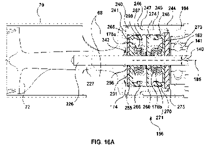
[0036] Figure 16A is a partial cross-sectional view of
another embodiment of an
MCS device having two lip seals facing one another, a distal disc, a middle
disc, and a proximal
disc contained in a seal housing.
[0037] Figure 16B is an isometric, exploded, partially cut-
away view of the seal
components of Figure 16A.
[0038] Figure 16C is a cross-sectional view of the seal
components of Figure 16A
shown isolated as a subassembly for facilitating manufacturing and assembly.
[0039] Figure 16D is a side cross-sectional view of another
embodiment of a seal
assembly, where a proximal disc has an extended radial contact surface and an
axial contact
surface.
[0040] Figure 16E is a perspective cross-sectional view of
an embodiment of a seal
assembly and impeller, where the seal assembly has a distally tapered distal
seal container.
[0041] Figures 16F and 16G are various views of a seal
assembly, an impeller and
a flow channel with a transparent housing for clarity, where the seal assembly
has a distally
tapered distal seal container and outlet strut support members.
[0042] Figure 17A is an isometric illustration of an
embodiment of an impeller with
a smooth base surface.
[0043] Figures 17B and 17C are isometric illustrations of
embodiments of
impellers having proximal vanes, in contrast to the impeller of Figure 17A,
which may
optionally be used with any MCS devices or seals described herein, for example
those shown
in Figures 9B, 10, 11, 12, 14A, 14B, 14C, 15, 16A, 16B, or 16C.
[0044] Figure 18A is a cross-sectional view of an embodiment
of an impeller
fastened to a drive shaft via an impeller base plate that may be used with the
various MCS
systems described herein.
[0045] Figure 18B is a cross-sectional view of an embodiment
of an impeller
fastened directly to a drive shaft that may be used with the various MCS
systems described
herein.
-6-
CA 03226767 2024- 1-23
WO 2023/014742
PCT/US2022/039209
[0046] Figure 18C is an isometric cut-away view of an
embodiment of an impeller
fastened to a drive shaft with a locking key that may be used with the various
MCS systems
described herein.
[0047] Figure 19 is a cross-sectional view of another
embodiment of an MCS
device having an axial lip seal and a radial face lip seal that may be used
with the various MCS
systems described herein.
DETAILED DESCRIPTION
[0048] The disclosure herein is related to a mechanical
circulatory support (MCS)
system and device having an impeller connected to a drive shaft that is driven
by a motor,
wherein blood is prevented from entering the motor with one or more seals
and/or other barrier
features. The following detailed description is directed to certain specific
embodiments. In
this description, reference is made to the drawings wherein like parts or
steps may be
designated with like numerals throughout for clarity. Reference in this
specification to -one
embodiment," "an embodiment," or -in some embodiments" means that a particular
feature,
structure, or characteristic described in connection with the embodiment is
included in at least
one embodiment of the invention. The appearances of the phrases "one
embodiment," "an
embodiment," or "in some embodiments" in various places in the specification
are not
necessarily all referring to the same embodiment, nor are separate or
alternative embodiments
necessarily mutually exclusive of other embodiments. Moreover, various
features are
described which may be exhibited by some embodiments and not by others.
Similarly, various
requirements are described which may be requirements for some embodiments but
may not be
requirements for other embodiments. Reference will now be made in detail to
embodiments of
the invention, examples of which are illustrated in the accompanying drawings.
A. Mechanical Circulatory Support (MCS) System
[0049] The sealing components described herein may be part
of a Mechanical
Circulatory Support (MCS) device or MCS system 10 such as the system in the
following
description.
[0050] As shown in Figures 1 and 2, the MCS system 10 may
include a temporary
(generally no more than about 6 hours, or no more than about 3 hours, 4 hours,
5 hours, 7
hours, 8 hours, or 9 hours) left ventricular support pump 22 for use during
various procedures,
such as high-risk percutaneous coronary intervention (PCI) performed in
elective or urgent,
-7-
CA 03226767 2024- 1-23
WO 2023/014742
PCT/US2022/039209
hemodynamically stable patients with severe coronary artery disease and/or
depressed left
ventricular ejection fraction. The system 10 may be used if a heart team,
including a cardiac
surgeon, has determined high risk PCI is the appropriate therapeutic option.
It is placed across
the aortic valve, for example via a single femoral arterial access.
[0051] The MCS system 10 includes a low-profile axial rotary
blood pump
mounted on a catheter such as an 8 French (Fr) catheter 16, where 1 Fr equals
1/3 millimeter
(mm). The pump may be referred to as an MCS pump or MCS device. When in place,
the
MCS pump can be driven by an MCS controller 180 to provide up to about 4.0
liters/minute
of partial left ventricular support, at about 60 mm Hg. No system purging is
needed due to
sealed motor. An improved bearing design can also avoid the need for purging.
By "purging"
it is meant that the system need not have a glucose or other type liquid purge
repeatedly
introduced into the system through tubing in order to prevent contamination of
the motor by
the blood. The MCS system 10 thus avoids the complexity associated with
systems that need
purging, and results in a simpler, less expensive device that is easier to
use. The system may
be visualized fluoroscopically, eliminating the need for placement using
sensors.
[0052] The system may further include an expandable sheath
12. The sheath 12
may allow 8 ¨ 10 Fr initial access size for easy insertion and closing,
expandable to allow
introduction of 14 Fr and 18 Fr pump devices, and return to a narrower
diameter around the 8
Fr catheter once the pump has passed. This feature may allow passage of the
heart pump
through vasculature while minimizing shear force within the blood vessel,
advantageously
reducing risk of bleeding and healing complications. Distention or stretching
of an arteriotomy
may be done with radial stretching with minimal shear, which is less harmful
to the vessel.
Access may be accomplished via transfemoral, transaxillary, transaortal, or
transapical
approach.
[0053] Figure 1 further shows a distal end of the MCS system
10 having the pump
22 mounted on the tip of an 8 Fr catheter 16. As used herein, "distal" and
"proximal" refer to
directions along the MCS system 10 in use that are, respectively, farther from
and closer to the
body, as further shown in FIGS. 3 and 9B as examples. An inlet tube portion 70
of the device
extends across the aortic valve 202. An impeller is located at the outflow
section 68 of the inlet
tube, drawing blood from the left ventricle 203 through the inlet tube portion
70 and ejecting
it out the outflow section 68 into the ascending aorta 204. The motor 145 is
mounted proximal,
-8-
CA 03226767 2024- 1-23
WO 2023/014742
PCT/US2022/039209
which may be directly proximal, to the impeller in a sealed housing
eliminating the need to
flush the motor prior to or during use. This configuration provides
hemodynamic support
during high-risk PCI, time and safety for a complete revascularization via a
minimally invasive
approach (rather than an open surgical procedure).
[0054] The system has been designed to eliminate the need
for motor flushing. The
system also provides increased flow performance up to 4.01/min at 60 mmHg with
acceptably
safe hemolysis due to a computational fluid dynamics (CFD) optimized impeller
that
minimizes shear stress. The seal and other features as described herein
contribute to these and
other advantages.
[0055] The MCS device 10 actively unloads the left ventricle
by pumping blood
from the ventricle into the ascending aorta and systemic circulation (shown in
Figures 1 and
2). When in place, the MCS device can be driven by the complementary MCS
Controller to
provide between 0.4 liters per minute (1/min) up to 4.0 1/min of partial left
ventricular support.
[0056] In general, the overall MCS system 10 may include a
series of related
subsystems and accessories, including one or more of the following:
= The MCS device 10 may include a pump, shaft, proximal hub, insertion
tool,
proximal cable, infection shield and guidewire aid. The MCS Device may be
provided sterile;
= The MCS shaft may contain the electrical cables and a guidewire lumen for
over-the-wire insertion;
= The proximal hub may contain guidewire outlet with a valve to maintain
hemostasis and connect the MCS shaft to the proximal cable, that connects the
MCS Device to the MCS Controller;
= The proximal cable may be 3.5 meters (m) (approximately 177 inches (in))
in
length and extend from the sterile field to the non-sterile field where the
MCS
Controller is located;
= An MCS insertion tool may be part of the MCS device 10 to facilitate the
insertion of the pump into an introducer sheath and to protect the inlet tube
and
the valves from potential damage or interference when passing through the
introducer sheath;
-9-
CA 03226767 2024- 1-23
WO 2023/014742
PCT/US2022/039209
= A peel-away guidewire aid may be pre-mounted on the MCS device 10 to
facilitate the insertion of the 0.018" placement guidewire into the pump and
into
the MCS shaft;
= A 3 meter long, 0.018" wide placement guidewire may be used, having a
soft
coiled pre-shaped tip for atraumatic wire placement into the left ventricle.
The
guidewire may be provided sterile;
= A 14 Fr introducer sheath with a usable length of 275 mm may be used to
maintain access into the femoral artery and provide hemostasis for a 0.035"
guidewire, the diagnostic catheters, the 0.018" placement guidewire, and the
insertion tool. The housing of the introducer sheath may be designed to
accommodate the MCS insertion tool. The introducer sheath may be provided
sterile;
= An introducer dilator may be compatible with the introducer sheath to
facilitate
atraumatic insertion of the introducer sheath into the femoral artery. The
introducer dilator may be provided sterile; and/or
= An MCS controller may drive and/or operate the MCS device, observe its
performance and condition as well as provide error and status information. The
powered controller may be designed to support at least about 12 hours of
continuous operation and contain a basic interface to indicate and adjust the
level of support provided to the patient. Moreover, the controller may provide
an optical and audible alarm notification in case the system detects an error
during operation. The MCS Controller may be provided non-sterile and be
contained in an enclosure designed for cleaning and re-use outside of the
sterile
field. The controller enclosure may contain a socket into which the extension
cable is plugged.
[0057] Referring to Figure 3, there is illustrated an
overall MCS system 10 in
accordance with one aspect of the present development, subcomponents of which
will be
described in greater detail below. The system 10 includes an introducer sheath
12 having a
proximal introducer hub 14 with a central lumen for axially movably receiving
an MCS shaft
16. The MCS shaft 16 extends between a proximal hub 18 and a distal end 20.
The hub 18 may
be provided with an integrated microcontroller or memory storage device for
device
-10-
CA 03226767 2024- 1-23
WO 2023/014742
PCT/US2022/039209
identification and tracking of the running time, which could be used to
prevent overuse to avoid
excessive wear or other technical malfunction. The microcontroller or memory
device could
disable the device, for example to prevent using a used device. They could
communicate with
the controller, which could display information about the device or messages
about its usage.
An atraumatic cannula tip with radiopaque material allows the
implantation/explanation to be
visible under fluoroscopy.
[0058] A pump 22 is carried by a distal region of the MCS
shaft 16. The system 10
is provided with at least one central lumen for axially movably receiving a
guide wire 24. The
proximal hub 18 is additionally provided with an infection shield 26. A
proximal cable 28
extends between the proximal hub 18 and a connector 30 for releasable
connection to a control
system typically outside of the sterile field, to drive the pump 22. The pump
22 may include
any of the seal embodiments described herein, such as those described with and
shown in FIGS.
9B-16C, 18A, 18B or 19.
[0059] Referring to Figure 4, the system 10 additionally
includes an insertion tool
32, having an elongate tubular body 36 having a length within the range of
from about 85 mm
to about 160 mm (e.g., about 114 mm) and an inside diameter within the range
of from about
4.5 mm to about 6.5 mm (e.g., about 5.55 mm), extending distally from a
proximal hub 34.
The tubular body 36 includes a central lumen adapted to axially movably
receive the MCS
shaft 16 and pump 22 there through, and sufficient collapse resistance to
maintain patency
when passed through the hemostatic valves of the introducer sheath. As
illustrated in Figure 4,
the pump 22 can be positioned within the tubular body 36, such as to
facilitate passage of the
pump 22 through the hemostatic valve(s) on the proximal end of an introducer
hub 14. A
marker 37 (Figure 7) is provided on the shaft 16 spaced proximally from the
distal tip 64 such
that as long as the marker 37 is visible on the proximal side of the hub 34,
the clinician knows
that the pump is within the tubular body 36.
[0060] The hub 34 may be provided with a first engagement
structure 39 for
engaging a complimentary second engagement structure on the introducer sheath
to lock the
insertion tool into the introducer sheath. The hub 34 may also be provided
with a locking
mechanism 41 for clamping onto the shaft 16 to prevent the shaft 16 from
sliding proximally
or distally through the insertion tool once the MCS device has been positioned
at the desired
location in the heart. The hub 34 may additionally be provided with a
hemostasis valve to seal
-11 -
CA 03226767 2024- 1-23
WO 2023/014742
PCT/US2022/039209
around the shaft 16 and also accommodate passage of the larger diameter MCS
device which
includes the pump. In one commercial presentation of the system, the MCS
device as packaged
is pre-positioned within the insertion tool and the guidewire aid is pre-
loaded within the MCS
device and shaft 16, as illustrated in Figure 4.
[0061] A guidewire aid 38 (also illustrated in Figure 8)
includes a proximal opening
90 configured to slip over and removably receive the distal tip 64 and/or
struts at the distal end
of the inlet tube 70 that define windows of the pump inlet 66. A guidewire
guide tube 83 having
a lumen therethrough is positioned within the proximal opening 90 and aligned
to pass through
the guidewire port 76 of the distal tip 64. The lumen of the guidewire guide
tube 83 is in
communication with a distal flared funnel opening 92 which gets larger in
cross-section in the
distal direction. The guidewire aid 38 may be provided assembled on the MCS
pump 22 with
the guidewire guide tube 83 pre-loaded along a guidewire path, for example
into the MCS
pump 22 through port 76, through a portion of the fluid path within the inlet
tube 70, out of the
MCS pump 22 through port 78, along the exterior of the MCS pump and into the
shaft 16
through port 80. This helps a user guide the proximal end of a guide wire into
the funnel 92
through the guidewire path and into the guidewire lumen of the MCS shaft 16. A
pull tab 94
may be provided on the guide wire aid 38 to facilitate grasping and removing
the guidewire
aid, including the guidewire guide tube 83, following loading of the
guidewire. The guidcwirc
aid 38 may have a longitudinal slit or tear line, for example along the funnel
92, proximal
opening 90 and guidewire guide tube 83, to facilitate removal of the guidewire
aid 38 from the
MCS pump 22 and guidewire 100.
[0062] Referring to Figures 5 and 6, an introducer kit 110
may include a guidewire
100, an introducer sheath 112, a dilator 114, and/or a guidewire aid 38, for
example as
discussed above. The guidewire 100 comprises an elongate flexible body 101
extending
between a proximal end 102 and a distal end 104. A distal zone of the body 101
may be pre-
shaped into a J tip or a pigtail, as illustrated in Figure 6, to provide an
atraumatic distal tip. A
proximal zone 106 is configured to facilitate threading through the MCS device
and extends
between the proximal end 102 and a transition 108. The proximal zone 106 has
an axial length
within the range of from about 100 mm to about 500 mm (e.g., about 300 mm).
[0063] The introducer kit 110 comprises a sheath 112 and a
dilator 114. The sheath
112 comprises an elongate tubular body 116, extending between a proximal end
118 and a
-12-
CA 03226767 2024- 1-23
WO 2023/014742
PCT/US2022/039209
distal end 120. The tubular body 116 terminates proximally in a proximal hub
122. Optionally,
the tubular body 116 is expandable or can be peeled apart. The proximal hub
122 includes a
proximal end port 124 in communication with a central lumen extending
throughout the length
of the tubular body 116 and out through a distal opening, configured for
axially removably
receiving the elongate dilator 114. Proximal hub 122 is additionally provided
with a side port
126, at least one and optionally two or more attachment features such as an
eye 128 to facilitate
suturing to the patient, and at least one and optionally a plurality of
hemostasis valves for
providing a seal around a variety of introduced components such as a standard
0.035"
guidewire, a 5 Fr or 6 Fr diagnostic catheter, an 0.018" placement guidewire
100, and the
insertion tool 32.
[0064] Additional details of the distal, pump region of the
MCS system are
illustrated in Figure 7. Pump zone 60 extends between a bend relief 62 at the
distal end of
shaft 16 and a distal tip 64. A pump inlet 66 is in fluid communication with a
pump outlet 68
by way of a flow path extending axially through the inlet tube 70. The pump
inlet may be
positioned at about the transition between the inlet tube and the proximal end
of distal tip 64,
which may be generally within about 5 cm or less or 3 cm or less from the
distal port 76. In
some embodiments, the distal tip 64 is radiopaque. For example, the distal tip
64 may be made
from a polymer containing a radiopacificr such as barium sulfate, bismuth,
tungsten, iodine. In
some embodiments, an entirety of the MCS device is radiopaque. In some
embodiments, a
radiopaque marker is positioned on the inlet tube between the pump outlet 68
and the guidewire
port 78 to indicate the current position of the aortic valve. Inlet tube 70
may comprise a highly
flexible slotted (e.g., laser cut) metal (e.g., Nitinol) tube having a
polymeric (e.g.,
Polyurethane) tubular layer to isolate the flow path. Inlet tube may have an
axial length within
the range of from about 60 mm and about 100 mm and in one implementation is
about 67.5
mm. The outside diameter is typically within the range of from about 4 mm to
about 5.4 mm,
and in one implementation is about 4.66 mm. The connections between the inlet
tube and the
distal tip and to the motor may be secured such as through the use of laser
welding, adhesives,
threaded or other interference fit engagement structures, or may be via press
fit.
[0065] The impeller 72 is positioned in the flow path
between the pump inlet 66
and pump outlet 68. In the illustrated embodiment, the impeller 72 is
positioned adjacent to
-13-
CA 03226767 2024- 1-23
WO 2023/014742
PCT/US2022/039209
the pump outlet 68. As is discussed further below, the impeller 72 is
rotationally driven by a
motor contained within motor housing 74, on the proximal side of the impeller
72.
[0066] The MCS device can be provided in either a rapid
exchange or over the wire
configuration. A first guide wire port 76 is in communication, via a first
guide wire lumen
through the distal tip component 64 and at least a portion of the flow path in
the inlet tube,
with second guide wire port 78 extending through a side wall of the inlet tube
70, and distal to
the impeller 72. This could be used for rapid exchange, with the guidewire
extending
proximally alongside the catheter from the second guidewire port 78.
[0067] The catheter may be provided in an over-the-wire
configuration, in which
the guidewire extends proximally throughout the length of the catheter through
a guidewire
lumen. In the over the wire embodiment of Figure 7, however, the guidewire
exits the catheter
via second guidewire port 78, extends proximally across the outside of the
impeller and motor
housing, and reenters the catheter shaft 16 via third guidewire port 80. See
also Figure 8. The
third guide wire port 80 is located proximal to the motor, and, in the
illustrated embodiment,
is located on the bend relief 62. Third guide wire port 80 is in communication
with a guide
wire lumen which extends proximally throughout the length of the shaft 16 and
exits at a
proximal guidewire port carried by the proximal hub 18.
[0068] The pump may be provided assembled with a removable
guidewire aid 38
having a guidewire guide tube 83 which tracks the intended path of the
guidewire from the
first guidewire port 76, proximally through the tip 64 and outside of the
inlet tube via second
guide wire port 78 and into the catheter via third guidewire port 80. In the
illustrated
implementation, the guidewire guide tube extends proximally within the
catheter to a proximal
end 81, in communication with, or within the guidewire lumen which extends to
the proximal
hub 18. The guidewire guide proximal end 81 may be positioned within about 5
mm or 10
mm of the distal end of the shaft 16, or may extend into the catheter shaft
guidewire lumen for
at least about 10 mm or 20 mm, such as within the range of from about 10 mm to
about 50
mm. The proximal end of a guidewire 102 may be inserted into the funnel 92,
passing through
the first (distal) guidewire port 76 and guided along the intended path by
tracking inside of the
guidewire guide tube. The guidewire guide tube may then be removed, leaving
the guidewire
in place.
-14-
CA 03226767 2024- 1-23
WO 2023/014742
PCT/US2022/039209
[0069] In one implementation, the distal end of the
guidewire guide tube 83 is
attached to the pull tab 94 of guide wire aid 38 and provided with an axially
extending split
line such as a weakening, slot or perforated tearable line. Removal may be
accomplished such
as by grasping the pull tab 94 and pulling out the guide wire tube as it
splits and peels away
along the split line. The inside surface of guide tube 83 may be provided with
a lubricious
coating, such as polytetrafluoroethylene (PTFE).
[0070] Figure 9A is a side view of one embodiment of an MCS
device that may be
used with the MCS system 10. Figure 9B is a partial cross-sectional view of a
region of the
MCS device as indicated in Figure 9A, showing an embodiment of a seal, among
other features.
Referring to Figures 9A and 9B, the impeller 72 is attached to a rigid motor
drive shaft 140,
which may be relatively short (e.g., in a range of 29 mm to 34 mm). Some of
the features
disclosed herein such as sealing elements (159) may be adapted for use with a
heart pump
having a motor that is kept external to the body and connected to an impeller
that is in the heart
with a long flexible driveshaft, which may have a length in a range of 1200 mm
to 1500 mm.
In the illustrated implementation, the drive shaft 140 extends distally into a
proximally facing
central lumen 142 in the impeller 72, such as through a proximal extension 154
on the impeller
hub 146, where it may be secured by a press fit, laser weld, adhesives or
other bonding
technique. The impeller 72 includes a radially outwardly extending helical
blade 178, which,
at its maximum outside diameter, is spaced apart from the inside surface of
tubular impeller
housing 82. The blade 178 may be spaced within the range of from about 40 pm
to about 120
pm. Impeller housing 82 may be a proximal extension of the inlet tube 70, on
the proximal
side of the slots 71 formed in the inlet tube 70 to provide flexibility distal
to the impeller. A
tubular outer membrane 73 encloses the inlet tube and seals the slots 71 while
preserving
flexibility of the inlet tube. Pump outlets 68 are formed in the sidewall of
the impeller housing,
axially aligned for example with a proximal portion of the impeller (e.g., a
proximal 25% to
50% portion of the impeller).
[0071] The impeller 72 may comprise a medical grade
titanium. This enables a
computational fluid dynamics (CFD) optimized impeller design with minimized
shear stress
for reduced damage of the blood cells (hemolysis) and a non-constant slope
increasing the
efficiency. This latter feature cannot be accomplished with a mold-based
production method.
-15-
CA 03226767 2024- 1-23
WO 2023/014742
PCT/US2022/039209
Electro polishing of the surface decreases the surface roughness to minimize
the impact on
hemolysis .
[0072] In some embodiments, the impeller hub 146 flares
radially outwardly in a
proximal direction to form an impeller base 150, which may direct blood flow
out of the outlets
68. A proximal surface of the impeller base 150 is secured to an impeller base
plate 152, which
may be in the form of a radially outwardly extending flange, secured to the
motor shaft 140.
For this purpose, the impeller base plate 152 may be provided with a central
aperture to receive
the motor shaft 140 and may be integrally formed with or bonded to a tubular
sleeve 154
adapted to be bonded to the motor shaft 140. In one implementation, the
impeller base plate
152 is first attached to the motor shaft 140 and bonded such as through the
use of an
adhesive. In a second step, the impeller 72 may be advanced over the shaft and
the impeller
base 150 bonded to the impeller base plate 152 such as by laser welding.
[0073] The distal opening in the aperture in impeller base
plate 152 may increase
in diameter in a distal direction, to facilitate application of an adhesive.
The proximal end of
tubular sleeve 154 may decrease in outer diameter in a proximal direction to
form an entrance
ramp for facilitating advancing the sleeve proximally over the motor shaft and
through the
motor seal 156, discussed further below.
[0074] The pump includes a motor 145 sealed from the blood
flow, due to the short
time of usage for high risk PCI (in some embodiments, no more than about 6
hours), configured
for use without flushing or purging. This provides the opportunity to directly
bond the impeller
72 on the motor shaft 140 as discussed in further detail below, removing
issues sometimes
associated with magnetic coupling such as the additional stiff length, space
requirements or
pump efficiency.
[0075] Motor 145 includes a stator 158 having conductive
windings surrounding a
cavity which encloses motor armature (rotor) 160 which may include a plurality
of magnets
rotationally secured with respect to motor shaft 140. The motor shaft 140
extends from the
motor 145 through a rotational bearing 162 and also through a seal 156 before
exiting the
sealed motor housing 164.
[0076] The seal 156 includes a seal holder 166 which
supports an annular seal ring
167, such as a polymeric seal ring. The seal ring 167 includes a central
aperture for receiving
the sleeve 154, or alternatively the drive shaft 140, and is biased radially
inwardly against the
-16-
CA 03226767 2024- 1-23
WO 2023/014742
PCT/US2022/039209
sleeve 154 to maintain the seal ring in sliding sealing contact with the
rotatable sleeve 154. A
spring 168, for example a garter spring made which may be made from spring-
stainless steel
or superelastic Nitinol, fits in a groove between the annular seal 167 and the
seal holder 166
and applies an inward facing force against the flexible annular seal 167,
which in turn maintains
a contact force between a lip 169 of the annular seal 167 and the rotating
shaft 140 or sleeve
154 within the central aperture. The outside surface of the sleeve 154 or
drive shaft 140 may
be provided with a smooth surface such as by electro polishing, to minimize
wear on the seal.
The outside surface of the sleeve 154 or drive shaft 140 may be provided with
a surface
treatment or coating such as a hydrophobic or hydrophobic treatment such as an
applied
coating or a micropatterned surface, to minimize wear on the seal.
[0077]
As shown in Figure 9B, the orientation of the seal may include having
the
annular seal 167 proximal to the seal holder 166 with the seal holder facing
distally toward the
impeller 72, wherein the distal face of the seal holder 166 is in contact with
flowing blood.
The seal 156 prevents blood from passing the annular seal into the motor
housing, which is
proximal to the seal.
[0078]
This is merely one example of a seal that may be used with the MCS
device
and pump 22. Other embodiments of seals that may be used on the various MCS
devices are
described herein, for example with respect to FIGS. 10-16C, 18A, 18B and 19.
[0079]
Further, the seal, vane and other features described herein may be used
with
a variety of different MCS systems and devices, and vice versa. For example,
any of the seal,
vane and/or other features described herein may be used with any of the
features, for example
the MCS system and device features as described in U.S. provisional
application no.
63/116616, filed November 20, 2020 and titled Mechanical Left Ventricular
Support System
for Cardiogenic Shock, in U.S. provisional application no. 63/116686, filed
November 20,
2020 and titled Mechanical Circulatory Support System for High Risk Coronary
Interventions,
in U.S. provisional application no. 63/224326, filed July 21, 2021 and titled
Guidewire, in
international PCT applications no. PCT/EP2019/076002 filed September 26, 2019
and titled
Sealed Micropump, in PCT/EP2019/062731 filed May 16, 2019 and titled Permanent-
magnetic radial rotating joint and micropump comprising such a radial rotating
joint, in
PCT/EP2019/062746 filed
May 16, 2019 and titled Rotor bearing system, in
PCT/EP2019/064775 filed June 6, 2019 and titled Line device for a ventricular
assist device
-17-
CA 03226767 2024- 1-23
WO 2023/014742
PCT/US2022/039209
and method for producing a line device, in PCT/EP2019/064780 filed June 6,
2019 and titled
Sensor head device for a minimal invasive ventricular assist device and method
for producing
such a sensor head device, in PCT/EP2019/064136 filed May 30, 2019 and titled
Line device
for conducting a blood flow for a heart support system, and production and
assembly method,
in PCT/EP2019/064807 filed June 6, 2019 and titled Method for determining a
flow speed of
a fluid flowing through an implanted, vascular assistance system and
implantable, vascular
assistance system, in PCT/EP2019/071245 filed August 7, 2019 and titled Device
and method
for monitoring the state of health of a patient, in PCT/EP2019/071233 filed
August 7, 2019
and titled Bearing device for a heart support system, and method for rinsing a
space in a bearing
device for a heart support system, in PCT/EP2019/068434 filed July 9, 2019 and
titled Impeller
housing for an implantable, vascular support system, in PCT/EP2019/069571
filed July 19,
2019 and titled Feed line for a pump unit of a cardiac assistance system,
cardiac assistance
system and method for producing a feed line for a pump unit of a cardiac
assistance system,
and/or in PCT/EP2019/075662 filed September 24, 2019 and titled Method and
system for
determining a flow speed of a fluid flowing through an implanted, vascular
assistance system;
the entire disclosure of each of which is incorporated by reference herein for
all purposes and
forms a part of this specification and description.
B. Control of motor speed with a device having a rotary shaft
seal
[0080] The controller 180 may be adapted to provide power to
the motor 145 to
maintain a target motor speed even when the cun-ent draw changes. The
rotational speed of
the impeller is directly related to the rotational speed of the driveshaft
since they are rigidly
connected. The flow rate of blood moved by the impeller is a function of the
rotational speed
of the impeller. The lip of a rotary shaft seal or the contacting surface of
elastomeric fluid
barriers may be designed to wear down during the duration of use. Frictional
force applied to
the rotary shaft by these parts may be expected to decrease over time as the
part wears down.
Motor current draw in a brushless DC motor, which is a function of the
frictional force and
other factors such as pressure differential, may likewise decrease over time
in response to
decreased friction. One way for a controller to detect motor speed may include
the use of hall
sensors in the MCS pump 22 or another portion of the device, which provide a
signal to the
controller that is an indication of rotational speed. Alternatively, a field-
oriented control (FOC)
-18-
CA 03226767 2024- 1-23
WO 2023/014742
PCT/US2022/039209
motor may be used, which beneficially allows an MCS device to be smaller by
excluding the
need for extra sensors. Smaller sized MCS devices, (e.g., <18FR, <16FR, <14FR,
about 14Fr)
may be particularly advantageous for high-risk PCI procedures. An FOC motor
maybe used to
measure the back-EMF that occurs while the motor is spinning. This back EMF
has a rhythmic
characteristic (e.g., sinusoidal) that represents the frequency of the motor's
rotation, which
may be detected by the controller as a feedback signal in a control algorithm,
which may
include a form of PID (proportional-integral-derivative) control. The
controller may adjust
current delivery to the motor according to the feedback signal to adjust the
motor speed so it
matches the target speed, which may include allowance for small fluctuations
around the target,
for example, fluctuation of plus or minus 0.006% of the target motor speed
(e.g., about 250
rpm for a target speed of 40k rmp) may be allowed without the controller
making adjustments
to the motor current.
C. Seal Configuration and Principle of Sealing
[0081] Without being bound by theory, rotary shaft lip seals
are typically oriented
with the lip facing the higher-pressure side, that is to say, the side that
has a fluid that the seal
is meant to prevent from passing to the other side. For example, the seals
shown in Figures 9B,
10, 11, 13A and 13B are shown oriented this way. As shown in Figure 9B for
example, the
seal 167 has a radially inner lip 169 extending distally from a proximal side
165 of the seal
167. The open distal side of the seal 167 having the cavity faces distally
toward the fluid side
and impeller 72, and the opposite proximal side 165, which may be flat, faces
proximally in
the opposite direction toward the motor 145.
[0082] Conventional sealing arrangements may have the seal
167 with the open
side facing distally, as described, as well as have the inner lip 169
contacting the rotating shaft.
The liquid on this open, lip-side of the seal may be in contact with the
intersection of the contact
lip 169 and the rotating shaft 140, and a very small amount of the liquid may
form a layer
between the lip 169 and shaft 140. If that liquid is blood, some constituents
of the blood such
as proteins may be affected by the mechanical forces or heat in this area
causing them to
coagulate or stick to the shaft, which may reduce the longevity of the seal
material or the
duration of functionality of the seal or pose a safety hazard to the patient.
Features described
-19-
CA 03226767 2024- 1-23
WO 2023/014742
PCT/US2022/039209
in relation to Figures 9B, 10, 11, 13A and 13B, such as grease, a distal
protection disc, a distal
protection disc having a contoured face, and/or impeller proximal vanes may
mitigate this risk.
[0083] Conversely, orienting the seal in the opposite
direction (e.g., such as the
orientation shown in Figure 12), with the lip and seal cavity facing away from
the blood, and
including a supply of lubricating grease in the seal cavity, the liquid that
contacts the lip-shaft
intersection may preferentially be the lubricant, which may slow down or
eliminate the
deposition of blood particles. It is with the discovery of this -reverse" or
"backward"
orientation of the seal that some of the embodiments described herein are
based on.
[0084] Further, the conventional approach to sealing is to
"keep fluid out."
However, the seal configurations described herein may be designed based on the
principle of
"keeping lubricant in," which in turn has the effect of being superior at
keeping fluid (such as
blood) out. For instance, including two seals facing one another, for example
as shown in
Figures 14A, 14B, 14C, 15, 16A, or 19, may provide further advantages. Each
seal cavity may
function as a depository for a lubricant, such as grease. Two seal cavities
facing one another
may create a larger depository for grease and the seals may function to retain
the grease in the
depository and prevent or slow it from escaping, while the lubrication in the
grease, which is
designed to withstand mechanical or thermal stress, is the liquid that
contacts the lip-shaft
intersection, instead of blood. Thus, the sealing arrangement results in
keeping blood out,
based on the principle of keeping grease in.
D. Embodiment with a single seal and distal disc
[0085] Figure 10 is a cross-sectional view of another
embodiment of an impeller
region of an MCS device having an alternative seal configuration. This
embodiment is similar
to that of Figure 9B with the exception that a distal protection disc 255
(also referred to as a
distal disc 255) is disposed distal to the annular seal. The distal protection
disc provides at least
a partial barrier between the patient's blood and the annular seal assembly,
which comprises a
seal holder 166, an annular seal 167 with a seal lip 169, and a garter spring
168. The distal
protection disc functions to reduce contact between blood and the seal by
closing a large
majority of an opening in the motor housing 164 where the seal is first
inserted. Thus, the distal
protection disc covers a large portion of the seal that is otherwise exposed
to blood. The distal
protection disc also creates a larger distance for blood to travel before it
meets the seal and acts
-20-
CA 03226767 2024- 1-23
WO 2023/014742
PCT/US2022/039209
as a thermal insulator between blood and heat producing regions of the device,
such as the
motor or the seal, to reduce risk of blood damage or clotting. The distal
protection disc 255
may be shaped like a circular disc with a central hole 171 through which the
drive shaft may
pass, and a thickness 172, for example a uniform thickness. It may fit tightly
(e.g., hermetically
sealed) against the motor housing 164 and therefor have a diameter equal to or
slightly larger
than the inner diameter of the motor housing to form a tight fit (e.g.,
friction fit). Optionally,
the distal protection disc may have a form-fitting feature 173 such as a
protruding ring around
its outer circumference or a groove that mates with a form-fitting feature of
the motor housing
164 for additional securement and sealing. Optionally, the distal protection
disc may be
adhered to the motor housing with adhesive or welding. The central hole 171 is
sized to have
a very small gap (e.g., a gap less than or equal to 0.05mm, less than or equal
to 0.01mm)
between the distal protection disc 255 and motor drive shaft 140, which may
include an
impeller proximal extension 154, passing though the central hole. In some
embodiments, the
distal protection disc does not contact the drive shaft 140 passing through
the central hole,
which ensures no additional friction is created or no additional torque loss
is created. For
example, the central hole 171 may have a diameter that is equal to the
diameter of the drive
shaft (140) plus twice the small gap (e.g., if the drive shaft has a diameter
of 0.6 mm the central
hole may have a diameter in a range of 0.62 to 0.70 mm). Optionally, a portion
of the central
hole may have an inner diameter that is less than the outer diameter of the
drive shaft to make
contact and function as a barrier to fluid. The thickness 172 may be in a
range of 0.1 mm to
1.5 mm (e.g., 0.3 to 1.2 mm, about 1 mm). The distal protection disc may be
made from a
polymer such as PEEK, PTFE, or an elastic polyurethane, which may beneficially
function as
a thermal insulator, allow slight deformation when fitting into the motor
housing, or may
minimize friction in the situation where the drive shaft (140) temporarily or
inadvertently
contacts the disc. Furthermore, a slippery surface of the material may enhance
flow of blood
in an axial gap 174, the space between the impeller 72 and the stationary
components facing
the impeller such as the motor housing 164 or distal protection disc in this
case. Alternatively,
a distal protection disc may be made from a metal such as titanium or steel.
Another function
of the distal protection disc 255 is to contain a lubricating grease 175 in a
seal cavity 176.
[0086] A seal cavity 176 is a volume of space within the
seal where grease may be
stored. For example, a seal cavity 176 as shown in figure 10, may be a volume
of space defined
-21-
CA 03226767 2024- 1-23
WO 2023/014742
PCT/US2022/039209
by a seal holder 166, an annular seal 167, and a distal protection disc 173.
The garter spring
168 may also be contained within the seal cavity 176. In the configuration
shown in Figure 10
the seal cavity 176 is facing distally, i.e., toward the impeller.
[0087] As shown in Figure 10, the impeller 72 may optionally
be connected to an
impeller base plate 152, and the impeller base plate may optionally have
proximal vanes 177.
Alternatively, an impeller may be directly connected to a motor drive shaft
140, and the device
may be with or without proximal vanes.
[0088] A method of manufacturing the device shown in Figure
10 may include
dispensing the grease into the seal cavity 176 that contains the garter spring
168 prior to
assembling the seal components (e.g., seal holder 166, annular seal 167,
spring 168) into the
motor housing 164. To completely fill the seal cavity and encompass the spring
in grease the
seal components containing dispensed grease may be spun in a centrifuge or
depressurized in
a vacuum chamber to remove air bubbles. The seal components may then be
pressed into the
motor housing and additional grease may be applied in the seal cavity or
distal to the annular
seal 167 before covering with the distal protection disc 255.
E. Embodiments with a single seal with distal and proximal discs
[0089] As shown in Figure 11, an MCS device may have both a
distal protection
disc 255, for example as described in relation to Figure 10, and a proximal
disc 275 (also
referred to as a proximal disc) disposed adjacent and proximal to the annular
seal 167, and
distal to the motor bearings 162 and motor. The proximal disc 275 may function
to reduce
contact between the motor bearings or motor and blood by sealing a majority of
the pathway
and creating larger distance for blood to travel before it meets the motor.
For example, in the
event that blood manages to pass the distal protection disc 255 and the
annular seal 167, the
proximal disc 275 may act as an additional measure to prevent blood from
passing further into
the motor housing. A combination of a distal protection disc 255 distal to one
or more annular
seals 167 and a proximal disc 275 proximal may restrict or reduce blood from
passing from
the external environment to the motor, may reduce thermal transfer from the
motor or bearings
162 to the annular seal 167 or to the blood in the external environment, or to
blood contacting
surfaces.
-22-
CA 03226767 2024- 1-23
WO 2023/014742
PCT/US2022/039209
[0090] Another benefit is that the proximal disc 275
together with the annular seal
may define a proximal cavity 189 on a proximal side of the annular seal 167 in
which a second
storage of lubricant or grease may be located. Optionally, a first storage of
lubricant or grease
may be located in the seal cavity 176, which in this case is on the distal
side of the annular seal
167. Having a first and second storage of lubricant or grease on each side of
the annular seal
may further reduce friction between the annular seal and drive shaft by
providing a larger
volume of grease or by providing grease on each side of the annular seal to
ensure there is a
continuous layer of grease between the annular seal lip 169 and moving parts
interacting with
the lip such as a drive shaft 140 or impeller proximal extension 154 thus
increasing the duration
of seal integrity. Optionally, the first lubricant contained in the seal
cavity 176 and the second
lubricant contained in the proximal cavity 189 may be different substances.
For example, the
first lubricant may be a higher consistency grease (e.g., NLGL grade 3 to 4),
which may
function to remain mostly contained in the seal cavity 176 and surround the
garter spring 168
at least for a duration of use to prevent blood from entering the garter
spring 168. The second
lubricant may be a relatively low consistency grease, which may function to
primarily lubricate
the seal lip 169. A portion of the second lubricant may also contact the seal
lip 169, the
interacting moving surface, or the distal protection disc to provide a low
friction interaction.
Alternatively, the same grease may be used in the seal cavity 176 and the
proximal cavity 189.
[0091] A method of manufacturing the device of Figure 11 may
include the grease
dispensing steps described above in relation to Figure 10, with an additional
step of pressing
the proximal disc 275 into the motor housing 164, and dispensing the first
storage of grease or
lubricant into the proximal cavity 189, prior to pressing the seal components
into the motor
housing.
F. Embodiments with a sin21e reversed seal and proximal disc
[0092] Another implementation of an MCS device having a
sealed rotary shaft is
shown in a cross-sectional illustration in Figure 12, wherein the rotary shaft
lip seal 167 is
oriented with its contact lip 169 and seal cavity 176, or its "open" side,
facing proximally, i.e.
toward the sealed motor 145 and away from the impeller 72. The opposite distal
side, which
may be flat as shown. faces the fluid side and impeller. A proximal disc 275
is positioned
proximal to the lip seal 167 and a lubricating grease is deposited in a space
defined by the seal
-23-
CA 03226767 2024- 1-23
WO 2023/014742
PCT/US2022/039209
cavity 175 and the proximal disc 275. Optionally, the MCS device may have an
impeller with
proximal vanes to increase blood flow in the axial gap 174, which may
beneficially remove
heat from the seal contact region to reduce a risk of blood coagulation.
Optionally, the lip seal
167 may have a leading edge 231 (see Figure 14B) to further prevent blood from
passing the
seal.
G. Embodiments with a distal protection disc and contoured flow
surface
[0093] Another implementation of an MCS device having a
sealed rotary shaft is
shown in a cross-sectional illustration in Figure 13A. As shown, the cross-
sectional view of
the MCS device has a distal facing lip seal 167 and a distal protection disc
212 having a distally
facing conical surface 214 with a concave contour and an impeller 210 with
blades having
proximal regions 211 that match the contoured face. The distal protection disc
212 may be
made from an elastomeric material such as PTFE, PEEK or a compound and have a
center bore
213 with an inner diameter that is slightly larger than the rotary shaft
position within the center
bore so contact is minimized or avoided. For example, a radial gap between the
rotary shaft
140 and the distal protection disc 212 may be in a range of 40 pm to 75 pm
(e.g., about 0.05
mm). Optionally, the distal protection disc may make a contact with the rotary
shaft at least
partially. Optionally, at least a portion of the central opening 213 has a
diameter that is less
than the outer diameter of the drive shaft 140, optionally by a difference in
a range of 0.01 to
0.05mm. The distal protection disc 212 may protrude from the motor housing 164
(e.g.,
protrude by a distance in a range of 1 to 2 mm), which may increase the
distance between the
seal 167 and flowing blood, which in turn may prevent blood from entering the
seal for a longer
duration or thermally insulate the blood from heat generated in the motor. The
protrusion of
the distal protection disc may have a contoured surface, for example a tapered
or conical
portion 214 optionally with a concave surface and a flat surface portion 215.
The flat surface
portion 215 may have a diameter equal to or similar to (e.g., within 0.01mm)
the diameter of
the flat portion of the base of the impeller 210. The shape of the tapered
portion 214 may
transition smoothly from the shape of the impeller hub 146, which may
facilitate directing
blood flow from the inlet tube 70 and out the outlet windows 68. A narrow
axial gap 174 is
between the impeller 210 with blades having proximal regions 211 that match
the contoured
face.
-24-
CA 03226767 2024- 1-23
WO 2023/014742
PCT/US2022/039209
[0094] Alternatively, as shown in Figure 13B the MCS device
has a distal facing
lip seal and a distal protection disc having a contoured face may have an
impeller 72 with a
non-matching proximal shape, such as a flat proximal edge 225.
[0095] An alternative implementation may have a distal
protection disc having a
contoured face and an impeller with a matching contour as shown in Figure 13A
or an impeller
with a non-matching contour as shown in Figure 13B, but with a proximally
facing lip seal and
optional proximal disc.
H. Embodiments with two radial shaft seals
[0096] Other embodiments of MCS devices having a sealed
rotary shaft are shown
in Figures 16A-16G. Figure 16A is a partial cross-sectional view of an MCS
device having
two lip seals (aka radial shaft seals) facing one another, a distal disc, a
middle disc, and a
proximal disc contained in a seal housing, Figure 16B is an isometric,
exploded, partially cut-
away view thereof, and Figure 16C is a cross-sectional view of the seal
components shown
isolated as a subassembly. Figure 16D shows an alternative embodiment of a
seal assembly
having a proximal disc with an extended radial contact surface and an axial
contact surface,
Figure 16E shows an embodiment of an MCS device having a sealed rotary shaft
and tapered
container, and Figures 16F and 16G show an embodiment of an MCS device having
a sealed
rotary shaft and tapered container with output struts, as further described
herein.
[0097] As shown in Figures 16A-16C, the device includes a
distal annular radial or
rotary shaft seal 266 having a radially inward contact lip 267 forming a seal
cavity 176a. The
contact lip 267 and seal cavity 176a of the distal seal 266 faces proximally.
The distal seal 266
thus has an "open side" facing proximally toward the motor, and a "flat side"
facing distally
toward the impeller and blood. The distal seal 266 is thus oriented
"backwards" from
conventional orientations. In some embodiments, the "open side- may be a side
of the seal
266 formed in part by upper and/or lower flanges or lips of the seal 266. A
cavity may be
formed by the open side of the seal 266. The cavity may be formed between an
end wall of
the seal 266 and the one or more flanges or lips of the seal 266. The cavity
may have a spring
and/or grease located therein. Further details of the end wall, lips, etc. are
described herein.
[0098] The device further includes a proximal annular radial
or rotary shaft seal
270, having a radially inward contact lip 271 forming a seal cavity 176b. The
contact lip 271
-25-
CA 03226767 2024- 1-23
WO 2023/014742
PCT/US2022/039209
and a seal cavity 176b of the proximal annular seal 270 faces distally. The
proximal seal 270
thus has an "open side" (as described above) facing distally toward the motor,
and a -flat side"
facing proximally toward the impeller and blood. Therefore, the seal assembly
includes the
proximal annular seal 270 and the distal annular seal 266 having opposite
orientations, with
their contact lips 267, 271 and seal cavities 176a, 176b facing one another.
[0099] The lips 267, 271 contact the shaft 140. The lips
267, 271 may extend along
the shaft 140. All or a part of the radially inward surface or surfaces of the
lips 267, 271 may
contact the shaft 140. The lips 267, 271 may be flat, and/or have non-flat
features, as described
in further detail herein, for example with respect to Figure 16C.
[0100] The seals 266, 270 may include radially outer lips
263, 264. The lips 263,
264 may contact a radially inward surface of the housing or other component of
the seal
compartment. The lips 263, 264 may extend along the housing or other
component. The lips
263, 264 may seal off the space between the seal 266, 270 and the housing or
other component.
The radially outer surfaces of the lips 263, 264 may be flat, non-flat, or
combinations thereof.
[0101] The lips 263, 264 may extend from respective end
walls 262, 259. The lip
263 extends distally from the end wall 262. The lip 264 extends proximally
from the end wall
259. The end walls 262, 259 may refer to the "flat" sides described herein.
The radially inner
lips 267, 271 may extend from the end walls 262. 259, as described. The outer
lips 263, 264
may extend perpendicular to the end walls 262, 259, either under no external
forces and/or
when installed in the seal compartment. The outer lips 263, 264 may have the
same or similar
features as the inner lips 267, 271, such as the leading edge, groove or
recess, etc.
[0102] In some embodiments, a middle elastomeric disc 260
may be positioned
between the proximal annular seal 270 and the distal annular seal 266. A
distal elastomeric
disc 255 may be positioned distal to the distal annular seal 266. A proximal
elastomeric disc
275 may be positioned proximal to the proximal annular seal 270.
[0103] Optionally, a seal housing made of a distal seal
container 240 and an
optional seal container cap 278 (see Figures 16B, 16C, and 16D), may contain
the seal
components in a subassembly. The subassembly may be inserted over the drive
shaft 140 and
into a motor housing 164. Alternatively, the seal components may be assembled
in the motor
housing by inserting the components separately and sequentially over the drive
shaft 140 into
a cavity in the motor housing. The seal components may then be covered with a
proximal
-26-
CA 03226767 2024- 1-23
WO 2023/014742
PCT/US2022/039209
(proximal) seal cap 278 that may be attached (e.g., welded, friction fit, form
fit, glued) to the
motor housing.
[0104] Both the distal elastomeric disc 255 and the middle
elastomeric disc 260
may be made from an elastomeric, biocompatible material such as PTFE, an
elastic
polyurethane, or a compound material such as PTFE and Polyimide. As shown in
Figure 16B,
one or more of the discs 255, 260 may have an inner diameter (ID) 256, 261
that is less than
the outer diameter (OD) of the drive shaft 140, which optionally may include
an impeller
proximal extension 154 such as that shown in Figure 10, that the inner
diameter contacts. For
example, the ID 256, 261 may be in a range of 80% to 95% (e.g., about 87%)
that of the OD
141. In one implementation, the ID 256, 261 is 0.52 mm +/- 0.02mm and the OD
141 is 0.60
mm +/- 0.01 mm. This dimensional difference creates high interference between
the
elastomeric discs 255, 260 and drive shaft to maintain a seal. For example, an
ideal interference
may be in a range of .070 mm to .080 mm The elastomeric discs 255, 260 may
both have a
thickness in a range of 80 p.m to 140 p.m (e.g., about 100 pm).
[0105] The properties of the elastomeric discs 255, 260 such
as high interference,
material durometer (e.g., in a range of 70 to 85 Shore), and thickness, may
allow for the disc
to deform when inserted over the drive shaft. For example, the disc may
compress outward
such that the disc ID may stretch, or the plane of the disc may curve
particularly in a region
close to the ID. The deformation of the disc may provide a contact pressure
with the drive shaft
140 even as the disc material wears over time. Furthermore, the high
interference provides an
amount of material that may be worn down before contact pressure is reduced to
zero, which
may prolong the functional duration of the disc 255, 260 to act as a blood
barrier. Furthermore,
the high interference may compensate for small tolerances of eccentricity of
the drive shaft
within the disc.
[0106] The properties of the discs 255, 260 may allow them
to act as a fluid barrier,
at least for a portion of the intended duration that the MCS device is in use,
while minimizing
friction or decrease in torque transmission. Additionally, the distal
elastomeric disc 255 may
function as a first barrier to blood at least for a portion of duration of
use. The middle
elastomeric disc 260, may function as an additional barrier to blood if it
manages to pass the
more distal barriers. Also, the disc 260 may act as a divider between the
distal annular seal
cavity 176a and proximal annular seal cavity 176b help to keep grease that is
contained in these
-27-
CA 03226767 2024- 1-23
WO 2023/014742
PCT/US2022/039209
cavities next to each annular seal, which in turn prolongs the functional
duration of the annular
seals. Optionally, the grease or lubricant dispensed in the distal seal cavity
176a may be the
same or different than that dispensed in the proximal seal cavity 176b. In
some embodiments,
the proximal disc 276 may have the same or similar features as the distal and
middle discs 255,
260.
[0107] Other than their relative position and orientation,
the distal seal 266 and
proximal seal 270 may have similar properties to one another or to other seals
156 disclosed
in relation to other implementations. For example, both the distal and
proximal seals may have
a seal holder 265, 274, an annular seal with a contact lip 267, 271, a seal
cavity 176a, 176b,
partially defined by the seal holder and annular seal, and/or a garter spring
269, 273 held in the
respective seal cavity 176a, 176b. The seals 266, 270 may have the same inner
diameter and
lip dimensions. Optionally the seals 266, 270 may have different outer
diameters primarily so
they are easily distinguishable from one another during manufacturing.
[0108] Alternative to a garter spring 269, 273 the seals may
contain a different
component that applies radially inward force such as an 0-ring or not have a
separate
component that applies the force, wherein properties of an elastomeric annular
seal with a
contact lip self-applies a radially inward contact force.
[0109] The distal and proximal annular seals 266, 270, may
be made from a
biocompatible elastomeric material such as PTFE, an elastic polyurethane, or a
compound
material such as PTFE and Polyimide, which optionally may have one or more
additives to
enhance durability. Grease may be contained in one or both seal cavities 176a,
176b, and
optionally a third grease reservoir held between the proximal seal and
proximal disc 275, and
may be the same grease or different greases. In one implementation a first
grease is deposited
in the distal seal cavity, which may have a higher viscosity and grease
consistency (e.g., NLGL
Class 4 or higher) than a third grease (e.g., NLGL Class 2) deposited in the
proximal seal cavity
or a second grease held in the third grease reservoir held between the
proximal seal and
proximal disc. In another implementation grease is deposited in the distal
seal cavity (e.g.,
NLGL Class 4 or higher) and an oil is deposited in the proximal seal cavity.
[0110] Optionally, the distal seal 266 may have a leading
edge 231 on its distal
face, which in addition to the contacting lip 267 is a surface of the distal
seal that contacts
rotating parts such as the drive shaft 140. The leading edge 231 is a portion
of the distal annular
-28-
CA 03226767 2024- 1-23
WO 2023/014742
PCT/US2022/039209
seal 266 with an inner diameter that is less than the inner diameter of a
portion of the contacting
lip 267 located proximally of the leading edge 231. The leading edge 231 may
be a portion of
the distal annular seal 266 with an inner diameter that is less than the outer
diameter of the
motor drive shaft 140 that the inner diameter mates with. For example, the ID
of the leading
edge may be in a range of 75% to 95% (e.g., 80% to 90%, about 87%) that of the
OD 141. In
one implementation the ID is 0.52 mm and the OD 141 is 0.60 mm. By making a
flush
connection to the rotating shaft 140 on the distal face of the seal, the
leading edge may function
to reduce the occurrence of blood getting actively drawn underneath the
contacting lip 267,
which may contribute to increasing the longevity of the seal. The distal
annular seal 266 may
be made as shown with a groove between the leading edge 231 and contact lip
267. The leading
edge 231 may be formed in part by an adjacent groove or recess formed in the
inner surface of
the lip 267. Alternatively, the leading edge 231 may have a smooth transition
to the contact
lip 267.
[0111] The orientation of the proximal seal 270, wherein the
contact lip 271 and
seal cavity 176b are directed distally, may facilitate the overall sealing
function in a number of
ways: for example, lubricating grease is held in the cavities 176b and 176a
between the distal
seal 266 and proximal seal 270 which coats the contact surface between the
contact lips 267,
271 and the drive shaft 140 to reduce wear, minimize reduction of torque
transmission or heat
formation, and resist ingress of blood; a higher pressure on the distal side
of the seal 270
relative to the proximal side (e.g., due to compressed grease held in the seal
cavity 1761) or in
the event that blood manages to pass through the more distal blood barriers)
may support the
contact pressure of the contact lip 271. The axial length of a portion of the
contact lip 271 that
contacts the shaft may be in a range of 0.3 to 0.8 mm (e.g.. about 0.5 mm).
[0112] Optionally, the device may have the proximal disc 275
positioned proximal
to the proximal seal 270 as shown in Figure 16A. The proximal disc may
function as another
barrier to prevent blood from entering drive shaft bearings 162 or the motor
compartment.
Furthermore, the proximal disc may help to account for small tolerances in
eccentricity of the
drive shaft. The proximal disc 275 may be made from a biocompatible
elastomeric material
such as PTFE or an elastic polyurethane or a compound and have a generally
disc shape with
a center hole having an inner diameter 276 through which the drive shaft 140
passes and makes
contact. The ID 276 may be in a range of 80% to 97% (e.g., about 93%) that of
the OD 141.
-29-
CA 03226767 2024- 1-23
WO 2023/014742
PCT/US2022/039209
In one implementation the ID is 0.56 mm and the OD 141 is 0.6 mm, which may be
greater
than the ID of the distal disc 255 or middle disc 260 to have less impact on
torque transmission
losses. Optionally, the proximal disc 275 may have a greater thickness than
the distal or middle
discs 255, 260 as shown in Figure 16A, which together with the elastomeric
properties of the
disc may provide an axial compression of the sealing components when the
proximal disc is
compressed between a distal seal container 240 and an edge on the motor
housing 164. For
example, the thickness of the proximal, middle and distal discs may be in a
range of 0.10 mm
to 0.15 mm. The proximal disc 275 may be axially compressed due to dimensions
of the stack
up of seal components in the axial direction and the space within the housing
that compresses
the stack. In some embodiments, the proximal disc 275 may be non-flat, e.g.
spherical, such
as a Belleville washer shape, to provide compression.
[0113] Figure 16B and 16C show the device of Figure 16A but
having a relatively
thinner the proximal disc 275, as well as the addition of a seal container cap
278. In this
implementation all of the sealing components are contained within a seal
container, for
example as a subassembly. The seal container may include a distal seal
container 240 and the
seal container cap 278, which may be both made from a metal such as stainless
steel or titanium
and connected securely for example, with a friction fit, form fit, threading,
or weld.
[0114] Figure 16D shows a seal 156 with the same features
and functions as the
seal in Figure 16B except as otherwise described. For example, the seal 156 of
Figure 16D
includes the proximal disc 275 having a first thickness 282 in the axial
direction and a second
thickness 283 in the axial direction that is greater than the first thickness
282. The second
thickness 283 may be located closer to the central axis 185 relative to the
first thickness 282.
The second thickness 283 may be at least as thick as a combination of the
first thickness 282
and a thickness of the seal container cap 278. The second thickness 283 may be
thicker than
the combination of the first thickness 282 and the thickness of the seal
container cap 278 so
that a proximally facing, protruding surface 284 protrudes from the cap 278 in
a proximal
direction (i.e. to the right, as oriented in the figure). When assembled, the
proximally facing,
protruding surface 284 may slidably contact a distal facing surface of at
least a portion of a
drive shaft bearing 162 (see Figure 16A) to provide another layer of sealing.
The increased
second thickness 283 allows for a greater radially inner surface 285 that
provides slidable
contact with the motor shaft 140, which may increase sealing performance.
-30-
CA 03226767 2024- 1-23
WO 2023/014742
PCT/US2022/039209
[0115] Referring to Figure 16B, the distal seal container
240 functions to contain
the seal components with or without the seal container cap 278 and facilitate
manufacturing.
The distal seal container may have a flat, rigid distal surface 241 that
provides a surface for
mechanically pressing the seal components into the motor housing 164 while
protecting the
softer, more fragile seal components. The flat, rigid surface 241 also ensures
the axial gap 174
between the surface 241 and impeller is consistent so blood in the axial gap
is expelled, and
the proximal face of the rotating impeller does not contact the seal
components inadvertently.
The surface 241 has a central hole 242, which has an inner diameter that is
larger than the outer
diameter of the drive shaft 140. For example, the hole 242 may have a diameter
that is in a
range of 0.080 mm to 0.150 mm (e.g.. about 0.100 mm) greater than the outer
diameter of
rotating parts passing through the hole, which may function as a physical
filter to prevent
particles from escaping the container as a risk management measure. For
example, the hole
242 may be in a range of 0.68 mm to 0.75 mm (e.g., about 0.70 mm) when the
drive shaft has
a diameter of 0.60 mm. In other words, a radial gap between the drive shaft
and the container
240 may be in a range of 0.040 mm to 0.075 mm (e.g., about 0.050 mm). The
distal seal
container has cylindrical side walls with an inner surface 248 that functions
to constrain the
seal components ensuring there is no lateral movement, which could compromise
the integrity
or longevity of the seals. A proximal chamfer 244 facilitates insertion into
the motor housing
during manufacturing. A distal chamfer 243 facilitates insertion of an inlet
tube 70, or
alternatively an impeller housing 82 over the distal seal container 240.
Furthermore, the distal
seal container 240 may have a recessed outer surface 245 for inserting into
the motor housing
164. An embodiment of a heart pump 22 having a seal element 156 as shown in
Figure 16A
may have a motor housing with a length no greater 25.5 mm. With additional
length added to
the motor housing by the seal subassembly and an optional wiring module
connected to the
proximal end of the motor housing, the length of the motor housing may be
extended to no
more than 33mm.
[0116] In another embodiment, as shown in Figure 16E, an MCS
device may have
a seal 156 in the form of a seal assembly, wherein the distal seal container
240 does not have
a flat distal face 241 as shown in Figure 16A but instead has a distally
tapering, e.g. conical,
face 321. The distally tapering conical face 321 may have a straight slope (as
shown in Figure
16E) or alternatively may have a curved slope, for example a concave contour
like the surface
-31-
CA 03226767 2024- 1-23
WO 2023/014742
PCT/US2022/039209
214 shown in Figure 13A, or a convex conical contour, or combinations thereof.
Due to the
inside geometry of a seal container having a conical distal face 321 compared
to a flat distal
face, a portion of the seal components may extend into the interior tapered
part of the distal
seal container 240. This may allow the length of a rigid motor housing to be
shorter. A shorter
rigid motor housing beneficially traverses a curve such as the aortic arch
more easily.
[0117] Further, the central hole 242 in the distal seal
container 240 is longer in the
conical-shaped container (Figure 16E) compared to the flat-shaped container
(Figure 16D) and
this extra length provides space for further sealing functions. The distal
disc 255 may have a
tubular extension 322 lining the inner surface of the central hole 242. The
tubular extension
322 may be part of and be the same material as the distal disc 255, for
example PTFE, and
optionally may be adhered to the surface of the central hole 242. The inner
surface of the
tubular extension 322 may be configured to slidably engage with the motor
shaft 140 to create
another sealing function to further extend the duration of sealing
performance. In some
embodiments, the tubular extension 322 may have a surface texture or treatment
on the inner
surface intended to at least partially contact the motor shaft 140. A surface
texture or treatment
may be included on protruding circumferential ribs, indents, or a micropattern
that may be
hydrophilic or hydrophobic which may function to prevent passage of blood or
hold
lubrication. In some embodiments, the distal disc 255 and/or the tubular
extension 322 may
be made from a material that holds lubricant, such as felt. In some
embodiments, a cavity may
be made in the conical portion of the distal seal container 240 to hold
lubrication. The tubular
extension 322 may terminate so its distal axial face 232 is flush with the
distal opening in the
distal seal container 240, or it may extend beyond the container 240 and
optionally make
contact with the impeller hub 146 creating an axial face seal. The length of
the tubular
extension 322 that extends beyond the seal container 240 may be about 100
microns to provide
an appropriate space between the impeller and distal seal container. In the
configuration shown
in Figure 16E, the impeller 72 may not include an impeller base 150, such as
shown in Figure
17. Further, the impeller vanes or blades 178 may have a flat proximal edge
225 as shown in
Figure 13B and 16G, or have a proximally extending proximal edge 211 following
the distal
contour 214, 321 of the distal seal container 240, as shown in Figure 13A,
16E, or 16F. A -flat
proximal edge" 225 may have an edge that is substantially orthogonal to the
central axis. In
some embodiments the flat proximal edges 225 or contoured proximal edges 211
of each
-32-
CA 03226767 2024- 1-23
WO 2023/014742
PCT/US2022/039209
impeller vane 178 may be connected to one another through an impeller hub 146
but not
through an impeller base, such as the impeller base 150 shown in Figures 17A,
17B, and 17C,
or impeller base plate 152 as shown in Figure 14A. In other words, there may
be an open space
defined by the impeller blades 178 through which blood flow may be directed in
an axial and
proximal direction toward a distally tapered surface 321 where the blood flow
is directed
radially outward through the outlet windows 68.
[0118] Figures 16F and Figure 16G are perspective and side
views respectively of
different embodiments of a portion of an MCS device with the motor, motor
housing, and
motor shaft removed in order to illustrate the seal container 240, the
impeller 72 and the inlet
tube 70 more clearly. The inlet tube 70 is shown transparent to reveal the
impeller 72 and the
seal container 240. The MCS device of Figures 16F and 16G may include any of
the seal
assemblies described herein, such as the seal assembly of FIG. 16C, of FIG.
16D, etc.
[0119] Figures 16F and 16G show alternative embodiments of
the distal seal
container 240, further having outlet struts 195. As further shown, in some
embodiments, the
devices may include the outlet struts 195 with outlet strut supports 325. The
outlet openings
or windows 68 are openings in a cylindrical flow cannula, such as an inlet
tube 70 or an
impeller cage, that contains an impeller, which moves blood through the
cannula from an inlet
to the outlet windows. The outlet struts 195 are structures that hold the
cannula to the motor
housing, directly or indirectly. The outlet struts 195 may include one or two
or three or four
or more webs elongated axially and arranged radially about a longitudinal axis
of the cannula.
The outlet struts 195 may be made by laser cutting the outlet windows 68 in
the inlet flow
cannula 70 and the remaining material between the outlet windows may be the
outlet struts
195, which may be substantially equal in geometry.
[0120] The outlet strut supports 325 may be connected to or
machined as part of
the distal seal container 240 and may each include a rigid structure spanning
between the distal
seal container 240 and an outlet strut 195, preferably on a position of the
outlet strut between
its proximal end and distal end, to provide increased rigidity and bending
resistance to the
outlet strut. The outlet strut supports 325 may have an axial length 326 that
is a portion (e.g.,
up to 100%, up to 50%, up to 30%, about 30%) of the outlet strut length 327.
The outlet strut
supports 325 may have an axial length 326 that is a portion (e.g., up to 100%,
up to 50%, up
to 30%, about 30%) of the axial length of the conical portion 321 of the
distal seal container
-33-
CA 03226767 2024- 1-23
WO 2023/014742
PCT/US2022/039209
240. For example, Figure 16G shows the outlet strut supports 325 having an
axial length 326
that is 100% the length of the conical portion 321, and Figure 16F shows the
outlet strut
supports 325 having an axial length 326 that is about 40% the length of the
conical portion
321. The outlet strut supports 325 may contact or be adhered to the outlet
struts 195 and be
made of a rigid material that provides increased strength or resistance to
bending to the outlet
struts 195.
[0121] The outlet strut supports 325 may further function to
direct the flow of blood
from inside the outlet struts 195 toward the outlet windows 68. For example,
the outlet strut
supports 325 may have a surface that is angled in a direction of blood flow
(i.e., from distal to
proximal) from a location on a radially inner surface of an outlet strut 195
to a location on a
radially outer edge of an outlet strut or in an outlet window 68 space. The
outlet strut supports
325 may have a leading edge 328, that is configured to face upstream into the
blood flow, and
that may be rounded. In Figure 16F, the leading edges 328 are positioned in
the center of the
widths of the outlet struts 195 and the outlet strut supports 325 each have a
surface that is
angled from the leading edge 325 to each adjacent outlet window 68 on each
side of the outlet
strut support. Alternatively, as show in Figure 16G, the outlet strut support
325 may have a
leading edge 328 positioned asymmetrically on an outlet strut 195, for example
near an edge
of an outlet strut, for example near an edge of an outlet strut facing a
radial component of blood
flow.
[0122] A method of manufacturing a seal subassembly may
include but not be
limited to inserting the seal components into the distal seal container in the
order and
orientation described herein, dispensing grease in the seal cavities
optionally sequentially or
simultaneously, releasing air bubbles using a centrifuge or vacuum chamber,
and closing the
seal container with the seal container cap 278. The seal subassembly may be
inserted over a
drive shaft 140, optionally into a motor housing, and connected to the motor
housing, for
example by laser welding an intersection which may include a rabbet 246 of the
distal seal
container 240 and a rabbet 247 of the motor housing. The impeller may be
connected to the
drive shaft, for example with an arrangement described herein in relation to
Figures 9B, 18A
or 18B. An impeller housing 82 or an inlet tube 70 having an integrated
impeller housing may
be connected to the motor housing and/or distal seal container 240. The device
may be
-34-
CA 03226767 2024- 1-23
WO 2023/014742
PCT/US2022/039209
packaged in an airtight package with air evacuated to prevent drying of the
grease dispensed
in the seals.
[0123] Alternative implementations of the concept shown in
Figure 16A are shown
in Figures 14A, 14B and 14C, which have two rotary shaft lip seals oriented
with their contact
lips facing one another. The embodiments of Figures 14A, 14B and 14C may have
the same
or similar features as described with respect to the seal of FIGS. 16A-16C,
and vice versa.
[0124] As shown in Figure 14A, the seal may be without a
distal, middle, and
proximal disc. Optionally, only one of the two seals may contain a garter
spring, which may
allow for more grease to be deposited in the seal cavity 176b in addition to
the seal cavity 176a
containing a garter spring. The two seals may be inserted into the motor
housing 164 and a
rigid metallic cap may be positioned over the seals and welded to the motor
housing.
Alternatively, the two seals may be contained in a sealed container 240 like
the one shown in
figure 16C and inserted as a component into the motor housing.
[0125] Figure 14B shows a similar implementation however
having a garter spring
in both the distal seal and the proximal seal. Furthermore, the distal seal
has a leading edge
231 configured to contact the rotary shaft distal to the contact lip.
[0126] Figure 14C shows another similar implementation
however the distal seal
does not have a leading edge. Instead, the device has an elastomeric distal
disc 255 sized to
contact the rotary shaft with a contact pressure, which may function as an
additional barrier to
blood.
I. Embodiments with pressure balancing features
[0127] The embodiment of Figure 15 includes pressure
balancing features.
Optionally, an MCS device with one or more rotary shaft seals, such as those
shown in FIGS.
9B-16C, 18A, 18B or 19, may include the pressure balancing features.
[0128] The pressure balancing features may transfer or
otherwise communicate
pressure between the surrounding blood and the grease held in a seal cavity.
Without being
bound by theory, a pressure gradient between the pressure of surrounding blood
applied to the
external side of the seal components and the pressure of the grease applied to
the internal side
of the seal components may cause blood to enter the seal or lubricant to leave
the seal. By
balancing the pressures and decreasing or eliminating the pressure gradient,
migration of blood
-35-
CA 03226767 2024- 1-23
WO 2023/014742
PCT/US2022/039209
or lubricant may be minimized. This may allow the device to prevent blood
regress and extend
the duration of functionality. A pressure balancing feature may be employed
with any of the
seal implementations disclosed within and may be used with one or two or more
rotary shaft
lip seals, one or more axial face lip seals, seal discs, seal containers, or
with seals oriented
distally or proximally, and in particular with at least one seal with its seal
cavity oriented
proximally.
[0129] For example, as shown in Figure 15, pressure
balancing features may be
employed with two rotary shaft seals oriented with their seal cavities 176a,
176b toward one
another. The pressure balancing feature includes at least one port or housing
channel 294
providing pressure communication between the at least one seal cavity and an
external
environment that has the same or similar pressure characteristics as the
external environment
that is in contact with the seal, such as within the left ventricle. For
example, a pressure
balancing housing channel 294 may be positioned within 20 mm (e.g., within 15
mm, within
mm, within 5 mm) of the axial gap 174 so both the housing channel 294 and
axial gap 174
are positioned in a left ventricle. A fluid tight, yet flexible, diaphragm 292
plugs each housing
channel 294 to prevent passage of blood or lubricant but passively deforms to
transfer pressure
and decrease the pressure differential between the external blood and internal
lubricant. If the
ambient pressure in the heart increases above the pressure within the seal
element, the
diaphragm 292 will flex inward and cause an increased pressure inside the
sealed cavity to
provide higher resistance to blood ingress. Conversely, if the ambient
pressure decreases
below the pressure within the seal element, the diaphragm 292 will flex
outward and cause a
decreased pressure inside the sealed cavity to provide less outward force to
the grease and
lubricant stored therein.
[0130] As shown in Figure 15, the seal cavity 176a, which
optionally is joined to a
second seal cavity 176b, may be filled with grease. The one or more seal
cavities are in fluid
communication with a seal channel 291 that is in fluid communication with a
housing channel
294 that is in fluid communication with a diaphragm 292. Alternatively, a disc
partitioner may
be positioned between two seal cavities and one, preferably the distal seal
cavity, may be in
fluid communication with the channel (not shown). The seal channel 291 may be
radial bores
or passages in a seal holder or between two seal holders 166a, 166b. The
housing channel 294
may be at least one (e.g., one, two, three, four, five, six) bores through one
or more housings
-36-
CA 03226767 2024- 1-23
WO 2023/014742
PCT/US2022/039209
that contain the seals. For example, the housing channel 294 may be through
the motor housing
164 as shown, or the seal housing if the seals are held in a container as
shown in Figure 16A.
Furthermore, in implementations wherein an MCS device has an impeller housing
or inlet tube
70 positioned over the motor housing 164, the housing channel may extend via a
hole 293
through said impeller housing or inlet tube and the diaphragm 292 may
optionally fill the hole
293. Alternatively, the hole 293 may be absent a diaphragm and have a smaller
diameter than
hole 292 that contains a diaphragm in order to anchor the diaphragm in place.
The diaphragm
may be silicone. Optionally, a lubricant reservoir 290 may be in fluid
communication with
both the seal channel(s) and the housing channel(s). The lubricant reservoir
290 may he made
by machining an annular groove in the motor housing and may function to hold
extra lubricant
or disperse pressure around the seals evenly. Optionally, the lubricant
reservoir may be filled
with a different fluid than the grease, such as sterile water with glucose.
Optionally, the
lubricant has a viscosity in a range of 0.30 to 1.30 mPas.
[0131] A method of manufacture may include dispensing
lubricant through at least
one of the housing channels 294 before applying the diaphragms. A second
housing channel
that is in fluid communication with the seal cavities and the first housing
channel may function
as a vent to allow air to escape as lubricant is injected and may improve the
ability to balance
pressure.
[0132] Optionally, an axially compressible washer, such as a
wave washer (not
shown), may be positioned proximal to the proximal seal 167b and rest against
a ridge or
surface such as a seal container cap (not shown). The compressible washer may
apply an axial
force to the proximal seal and increase pressure in the seal cavities filled
with grease or cause
the diaphragm(s) to slightly bulge outward when the device is in atmospheric
pressure or
fluctuate about a relatively neutral position when exposed to blood pressure.
J. Embodiments with rotary shaft seal and axial face seal with a
barrier fluid
[0133] Figure 19 shows a schematic representation of a heart
pump 22 according
to a design example. The heart pump 22 comprises a housing 164, an impeller
72, a motor 115,
a sealing element 300 and a barrier fluid 301. The heart pump 22 represents a
blood pump,
typically an axial flow pump, which is driven by the motor 115 in the form of
an integrated
-37-
CA 03226767 2024- 1-23
WO 2023/014742
PCT/US2022/039209
electric motor, and which generates a required blood flow by means of the
impeller 72 when
the heart pump 22 is implemented in the body of a patient.
[0134] The housing 164 has an interior 302 and an opening
303 to the interior 302.
The interior 302 is shaped to accommodate the motor 115. The motor 115 is
located in the
interior 302 and has a shaft 140. The motor 115 is shaped to drive the shaft
140. The shaft 140
passes through the opening 303 and is coupled to the impeller 72 to drive the
impeller 72. The
impeller 72 has at least one blade 178, here exemplarily two blades 178, which
are suitable for
pumping blood. The impeller 72 is arranged on the drive shaft 140 that extends
from the motor
housing. The sealing element 300 is located between the impeller 72 and the
motor housing
164 and is designed to seal the axial gap 174 between the impeller 72 and the
motor housing
164. The sealing element 300 may be attached to the impeller 72.
Alternatively, the sealing
element 300 is attached to the motor housing 164. The sealing element 300 is
ring-shaped to
seal around the gap 174 completely. The sealing element 300 may be an axial
face seal.
Optionally, the heart pump 22 has a further sealing element 167, whereby the
further sealing
element 167 is located at the opening 303 and is designed to seal the interior
302 of the motor
housing 164 against a space 305 between the motor housing 164 and the impeller
72. In this
case, the space 305 is sealed by the sealing element 300 against the
environment of the heart
pump 22 and by the further sealing element 167 against the interior 302.
Optionally the further
sealing element 167 may be in the form or have other features of other radial
rotary shaft
sealing elements disclosed elsewhere herein such as a lip seal, or multiple
lip seals.
[0135] According to this example, the barrier fluid 301 in
the space 305 is held in
the space 305 by the sealing elements 300, 174. The barrier fluid 301 prevents
a medium from
the environment of the heart pump 22 from penetrating into an interior of the
motor 115. If the
additional sealing element 167 is omitted, the space 305 is fluidically
connected to the interior
302 of the housing 164. In this case, the barrier fluid 301 can expand into
the interior of the
motor 115. The motor interior can thus be flooded with barrier fluid 301.
[0136] The shaft 140 is mounted opposite the housing 164.
For this purpose, two
bearings 162 are arranged in the interior 302 as an example to support the
shaft 140. According
to one design example, during operation of the heart pump 22 blood, which can
also be
described as fluid, is fed axially to the impeller 72, sucked in here, and
expelled radially and
diagonally, for example through openings 68. The impeller 72 is fixed with the
shaft 140 of
-38-
CA 03226767 2024- 1-23
WO 2023/014742
PCT/US2022/039209
the motor 115, which provides the required drive power. According to a design
example, the
shaft 140 is supported by at least one radial and at least one axial bearing
162. Optionally, the
bearings 162 can also be used in combination with a radial-axial bearing 162.
[0137] The sealing element 300 can be contact or non-
contact, e.g., as labyrinth
seal or gap seal or as a combination of both. Furthermore, at least one
additional sealing
element 167 is optionally provided to seal the shaft 140 against the housing
164. The space
between the sealing element 300 and the motor housing 164 is filled with the
ideally
biocompatible barrier fluid 301, which prevents the medium to be pumped
(blood) from
penetrating into the interior of the motor over the entire required operating
time and service
life of the heart pump 22. Optionally, the additional sealing element 167
reduces leakage of
the barrier fluid 301 in the motor interior. According to another possible
design example the
complete interior of the motor is filled with the barrier fluid 301. The
barrier fluid 301 ideally
consists of a biocompatible medium, e.g., glucose or endogenous fat.
Furthermore, viscosity
of the fluid should be preferred, which neither causes too much friction loss
nor, due to its low
viscosity, evaporates from the space 305 during operation. Furthermore, good
compatibility
with the motor components should be sought.
[0138] For example, the heart pump 22 is available as a
temporary or short-term
Ventricular Assist Device (VAD) or mechanical circulatory support (MCS) pump,
which can
be implanted very quickly. For this purpose, the Heart Pump 22 is designed as
a simple system
according to a design example. The advantage is that although the Heart Pump
22 requires an
external energy supply, it does not require an irrigation medium, which serves
to protect the
motor 115 from blood penetration. The heart pump 22 comes without a such
external forced
flushing.
[0139] According to one design example, the heart pump 22
essentially consists of
the impeller 72 and the sealing element 300, which is firmly connected to the
impeller 72 and
has a sealing function against the housing 164, or alternatively a
corresponding sealing element
which is firmly connected to the motor housing 164 and has a sealing function
with respect to
the impeller 72. Furthermore, the heart pump 22 has an optional sealing
element 167 which
seals the housing 164 against the rotating shaft 178. A special feature here
is that the space 305
between the two sealing elements 300, 167 is filled with the barrier fluid,
which prevents the
-39-
CA 03226767 2024- 1-23
WO 2023/014742
PCT/US2022/039209
pumped medium (blood) from penetrating into the interior of the motor over the
operating
period.
K. Embodiments with surface treatment
[0140] Optionally, a surface treatment may be applied to one
or more parts to help
prevent coagulation of blood or blood particles from sticking to the surface,
or to facilitate
movement of blood, or reduce friction between a seal lip or disc and a rotary
shaft. For
example, a surface treatment may be applied to the proximal surface of the
impeller, the rotary
shaft, the distal surface of a seal container 241. A surface treatment may be
a hydrophilic
coating such as Polyvinylpyrrolidon (PVP) having a thickness in a range of 3
to 5 gm, or a
hydrophobic coating such as Perfluoralkoxy (PFA) having a thickness in a range
of 10 to 20
gm. A surface treatment may be a micropatterned surface with hydrophilic or
hydrophobic
properties. A surface treatment or material used to make a component such as a
seal holder
166, may include nitrided titanium, ceramic, or ceramic impregnated with PTFE.
L. Embodiments with superabsorber
[0141] Optionally an MCS device may contain a superabsorber
in a rotary shaft
seal assembly, such as those disclosed herein. For example, a superabsorber
material may be
provided on a carrier material such as a thin piece of foil or cellulose and
positioned in a seal
assembly such as in or in contact with a seal cavity. The carrier (not shown)
may be in the form
of a disc with a center hole and positioned on one or more of a distal side of
the middle disc
260, a proximal side of the middle disc 260, or the distal side of the
proximal disc 275 of the
implementation shown in Figure 16A. Alternatively or additionally, a
superabsorber may be
an encapsulated superabsorber granulate that is placed within a seal cavity,
optionally mixed
into the grease. The rotary shaft lip seal or other features such as a leading
edge of a seal or a
disc may provide the primary barrier to blood ingress, however in case some
blood enters the
seal a superabsorber may absorb the blood and prevent it from passing further
into the motor
or coagulating between the lip and rotary shaft. A hydrophilic behavior of the
superabsorber
may avoid absorbing oil from the grease. If blood is absorbed, the absorber
may increase in
volume and add pressure on the seal lip to further prevent blood from
entering. A superabsorber
may include a small amount (e.g., <50 microliters) of sodium polyacrylate.
-40-
CA 03226767 2024- 1-23
WO 2023/014742
PCT/US2022/039209
M. Embodiments with impeller proximal vanes
[0142] An MCS device may have features of implementations
disclosed herein and
may optionally further include an impeller 72 having a central impeller hub
146, axial flow
blades (e.g., two blades) 178 radially extending from the hub 146, an impeller
base 150 at a
proximal end of the hub 146 and radial flow blades 177 arranged on a plane
perpendicular to
the axis of the hub, and a central bore 226 in and coaxial with the hub.
Optionally, the impeller
may have proximal vanes 177 on the proximal face of the impeller base 150.
[0143] Without being bound by theory, proximal vanes are
structural protrusions,
or alternatively indentations, extending radially on the proximal surface of
the impeller base
that enhances fluid flow in an axial gap 174 when the impeller rotates, which
may improve
convective heat transport, improve efficiency, and reduce damage of blood
cells. Heat is
generated in the motor and bearings and via friction between the seal and
rotary shaft and can
cause blood particles to coagulate. Removing heat from this area may reduce
the risk of blood
coagulation. A small axial gap is preferable over a large gap, which can
generate losses in
efficiency and vortex areas, which in turn can build pressure, decrease
efficiency and damage
blood. The proximal vanes increase flow while allowing a very small axial gap,
for example
an axial gap in a range of 0.08 mm to 0.3 mm. Furthermore, the proximal vanes
may increase
the radial component of the mixed axial and radial blood flow to move blood
out of the outlet
windows 68 or may decrease fluid pressure in the axial gap 174 which may
improve the
function of the seal.
[0144] Figure 17A shows an isometric schematic illustration
of an impeller 72 of
and MCS device that does not have proximal vanes but instead has a smooth
proximal surface
225 on the impeller base 150. In contrast, Figures 17B and 17C show impellers
with two
versions of proximal vanes 177. Preferably, the impeller is balanced about its
central axis so
it rotates smoothly without vibration. To balance the impeller the proximal
vanes 177 may be
made to be radially symmetric, for example at least two proximal vanes on
opposing sides of
equal weight and shape may provide radial symmetry; three proximal vanes
positioned 120
degrees about the central axis may provide radial symmetry; four proximal
vanes positioned
90 degrees about the central axis may provide radial symmetry as shown in
figures 17B and
17C. As shown in Figure 17B the proximal vanes 177 may be in a plane parallel
to the impeller
base 150 and be curved to encourage radially outward flow of blood. For
example, the
-41 -
CA 03226767 2024- 1-23
WO 2023/014742
PCT/US2022/039209
curvature of the proximal vanes may be convex in the direction of rotation.
Alternatively, the
proximal vanes may be straight and extend radially from the center bore 226 as
shown in Figure
17C. The proximal vanes may optionally have inner edges that are not connected
to one another
as shown in Figure 17B or may be connected to one another as shown in Figure
17C. Impeller
proximal vanes 177 may be fabricated, for example machined or molded, directly
on an
impeller base 150 as shown in Figure 18B, or alternatively be fabricated on a
separate
component such as an impeller base plate 152 that is connected to the impeller
as shown in
figure 18A.
N. Embodiments of connectin2 the impeller to the drive shaft
[0145] The impeller 72 may be connected to the drive shaft
140 with a consistent
axial gap 174 and in a rigid manner that reduces risk of contaminating or
damaging the rotary
shaft seal(s). In a first exemplary implementation as shown in Figure 9B, an
impeller 72 may
be connected to a drive shaft 140 by first connecting an impeller base plate
152 to the drive
shaft, wherein the base plate has a tubular proximal extension 154 extending
proximally. This
implementation is described above in detail. Optionally the base plate 152 may
have impeller
proximal vanes 177 on the proximal face of the base plate 152 facing into the
axial gap 174.
[0146] In a second exemplary implementation as shown in
Figure 18A, an impeller
base plate 152 having a tubular extension 154 may be first connected to the
drive shaft 140. In
contrast to the implementation of Figure 9B the base plate 152 may be oriented
with the tubular
extension 154 aiming distally. Optionally, the tubular extension may have a
non-circular
cylindrical extension to rotationally lock the impeller to the tubular
extension and base plate.
The base plate may be connected to the drive shaft 140 by laser welding or
adhesive. For
example, a laser weld may be applied to the interface between the distal end
of the tubular
extension 154 and drive shaft 140 while a spacer is temporarily placed in the
axial gap 174 to
ensure a consistent gap and straight alignment. The impeller 72 may then be
connected to the
base plate 152 by inserting the tubular extension 154 into a central bore 266
in the impeller.
The impeller 72 may be connected to the driveshaft 140, for example by
dispensing glue in an
impeller central bore 226 and sliding the impeller over the drive shaft
wherein side bore(s) 227
allow air or excess glue to escape Optionally, the base plate may have
impeller proximal vanes
177 on its proximal face aiming into the axial gap 174.
-42-
CA 03226767 2024- 1-23
WO 2023/014742
PCT/US2022/039209
[0147] In a third exemplary implementation as shown in
Figure 18B, an impeller
72 may be connected directly to the drive shaft 140, for example without a
base plate. The
impeller 72 may be connected to the driveshaft 140, for example by dispensing
glue in an
impeller central bore 226 and sliding the impeller over the drive shaft
wherein side bore(s) 227
allow air or excess glue to escape, while ensuring an axial gap 174 of a known
distance, for
example by implementing a manufacturing jig or inserting a spacer in the gap
174.
[0148] In a fourth exemplary implementation as shown in
Figure 18C, an impeller
72 and an impeller base plate 152 may be connected to a drive shaft 140 with a
key 309. The
impeller base plate 152 may optionally have a tubular extension oriented
proximally and may
optionally have impeller proximal vanes 117 oriented proximally into the axial
gap 174. The
impeller base plate 152 may have a recess 310 that the key 309 tightly fits
into with a portion
extending from the recess 310. The impeller 72 may also have a recess 311 in
which the portion
of the key 309 extending from the recess 310 may mate into. Recess 311 may
have additional
space to make room for a weld seam on the distal face of the key 309 and
around the shaft 140.
The key 309, recess 310 and recess 311 have mating shapes and are non-circular
in the plane
transverse to the axis of rotation so the key 309 cannot spin within the
recesses but instead
transfers rotational force from the shaft 140 to the impeller base plate 152
and impeller 72
through the key 309, at least in part. A method of assembly may include
assembling a seal
(e.g., a seal subassembly such as the one shown in figure 16A, 16B or 16C, or
another
implementation of a seal disclosed herein) over the drive shaft 140 extending
from a motor;
positioning the impeller base plate 152 having a recess 310 on the drive shaft
while maintaining
a desired axial gap 174, for example with a temporary spacer; positioning the
key 309 over the
drive shaft 140 and into the recess 310; laser welding the key 309 to the
drive shaft 140 to
create a weld seam 312; positioning the impeller 72 on the assembly so the
drive shaft 140 is
inserted into the impeller's central bore 226, the key 309 is inserted into
the impeller's recess
311, and the base of the impeller is in contact with the impeller base plate
152. The impeller
72 may be laser welded to the base plate 152 to create a weld seam 313.
Optionally, an adhesive
may be applied in the impeller' s central bore 226 before inserting the drive
shaft in which case
a side port 227 may allow excess adhesive or air to escape. Optionally,
adhesive may be applied
between the impeller 72 and impeller base plate 152, between the base plate
152 and shaft 140,
or the key 309 and the impeller or base plate. Optionally, in this
implementation the impeller
-43-
CA 03226767 2024- 1-23
WO 2023/014742
PCT/US2022/039209
72 and the impeller base plate 152 may be made from different materials. In
this case an
adhesive may be used to bond them together with the key 309 held in the cavity
between them
and welded to the shaft 140.
0. Modifications
[0149] Various modifications to the implementations
described in this disclosure
will be readily apparent to those skilled in the art, and the generic
principles defined herein can
be applied to other implementations without departing from the spirit or scope
of this
disclosure. Thus, the disclosure is not intended to be limited to the
implementations shown
herein, but is to be accorded the widest scope consistent with the claims, the
principles and the
novel features disclosed herein. The word "example" is used exclusively herein
to mean
"serving as an example, instance, or illustration." Any implementation
described herein as
"example" is not necessarily to be construed as preferred or advantageous over
other
implementations, unless otherwise stated.
[0150] Certain features that are described in this
specification in the context of
separate implementations also can be implemented in combination in a single
implementation.
Conversely, various features that are described in the context of a single
implementation also
can be implemented in multiple implementations separately or in any suitable
sub-
combination. Moreover, although features can be described above as acting in
certain
combinations and even initially claimed as such, one or more features from a
claimed
combination can in some cases be excised from the combination, and the claimed
combination
can be directed to a sub-combination or variation of a sub-combination.
[0151] Similarly, while operations are depicted in the
drawings in a particular
order, this should not be understood as requiring that such operations be
performed in the
particular order shown or in sequential order, or that all illustrated
operations be performed, to
achieve desirable results. Additionally, other implementations are within the
scope of the
following claims. In some cases, the actions recited in the claims can be
performed in a
different order and still achieve desirable results.
P. Tcrminolouv
[0152] It will be understood by those within the art that,
in general, terms used
herein are generally intended as "open" terms (e.g., the term "including"
should be interpreted
-44-
CA 03226767 2024- 1-23
WO 2023/014742
PCT/US2022/039209
as "including but not limited to," the term "having" should be interpreted as
"having at least,"
the term "includes" should be interpreted as "includes but is not limited to,"
etc.). It will be
further understood by those within the art that if a specific number of an
introduced claim
recitation is intended, such an intent will be explicitly recited in the
claim, and in the absence
of such recitation no such intent is present. For example, as an aid to
understanding, the
following appended claims may contain usage of the introductory phrases -at
least one" and
-one or more" to introduce claim recitations. However, the use of such phrases
should not be
construed to imply that the introduction of a claim recitation by the
indefinite articles "a" or
"an" limits any particular claim containing such introduced claim recitation
to embodiments
containing only one such recitation, even when the same claim includes the
introductory
phrases "one or more" or "at least one" and indefinite articles such as "a" or
"an" (e.g., "a"
and/or "an" should typically be interpreted to mean "at least one" or "one or
more"); the same
holds true for the use of definite articles used to introduce claim
recitations. In addition, even
if a specific number of an introduced claim recitation is explicitly recited,
those skilled in the
art will recognize that such recitation should typically be interpreted to
mean at least the recited
number (e.g., the bare recitation of "two recitations," without other
modifiers, typically means
at least two recitations, or two or more recitations). Furthermore, in those
instances where a
convention analogous to -at least one of A, B, and C, etc." is used, in
general such a
construction is intended in the sense one having skill in the art would
understand the
convention (e.g., "a system having at least one of A, B, and C" would include
but not be limited
to systems that have A alone, B alone, C alone, A and B together, A and C
together, B and C
together, and/or A, B, and C together, etc.). In those instances where a
convention analogous
to "at least one of A, B, or C, etc." is used, in general such a construction
is intended in the
sense one having skill in the art would understand the convention (e.g., "a
system having at
least one of A, B, or C" would include but not be limited to systems that have
A alone, B alone,
C alone, A and B together, A and C together, B and C together, and/or A, B,
and C together,
etc.). It will be further understood by those within the art that virtually
any disjunctive word
and/or phrase presenting two or more alternative terms, whether in the
description, claims, or
drawings, should be understood to contemplate the possibilities of including
one of the terms,
either of the terms, or both terms. For example, the phrase "A or B" will be
understood to
include the possibilities of "A" or -B" or "A and B."
-45-
CA 03226767 2024- 1-23
WO 2023/014742
PCT/US2022/039209
Q. Example Embodiments
The following is a non-exhaustive list of numbered example embodiments:
1. A seal for a heart pump, the seal comprising:
a distal radial shaft seal configured to surround a motor shaft of the heart
pump, with a
flat side of the distal radial shaft seal facing distally and an open side of
the distal radial shaft
seal facing proximally; and
a proximal radial shaft seal configured to surround the shaft and be located
proximally
of the distal radial shaft seal, such that the proximal radial shaft seal is
located farther from an
impeller of the pump than the distal radial shaft seal, with a flat side of
the proximal radial
shaft seal facing proximally and an open side of the proximal radial shaft
seal facing distally.
2. The seal of Embodiment 1, wherein the distal radial shaft seal comprises
a
radially inner lip configured to contact the shaft and to extend from the flat
side of the distal
radial shaft seal in a proximal direction.
3. The seal of any of Embodiments 1 or 2, further comprising a distal
spring
located at least partially within the open side of the distal radial shaft
seal and configured to
compress a radially inner lip of the distal radial shaft seal radially
inwardly onto the shaft.
4. The seal of any of Embodiments 1 to 3, further comprising a proximal
spring located at least partially within the open side of the proximal radial
shaft seal and
configured to compress a radially inner lip of the proximal radial shaft seal
radially inwardly
onto the shaft.
5. The seal of any of Embodiments 1 to 4, further comprising one or more
discs comprising a central opening with an inner diameter configured to be
less than the outer
diameter of the shaft.
6. The seal of Embodiment 5, wherein a radially inner edge of the central
opening of each of the discs is configured to wear off in response to rotation
of the shaft.
7. The seal of any of Embodiments 1 to 6, further comprising grease located
between the distal radial shaft seal and the middle disc and between the
middle disc and the
proximal radial shaft seal.
8. The seal of any of Embodiments 1 to 7, wherein each of the distal and
proximal radial shaft seals have radially outer lips configured to contact an
inner side of a
housing.
-46-
CA 03226767 2024- 1-23
WO 2023/014742
PCT/US2022/039209
9. The seal of any of Embodiments 1 to 8, wherein the seal is configured to
be
assembled with the heart pump and delivered to the heart via a catheter.
10. The seal of any of Embodiments 1 to 9, further comprising a housing
having
a distal end wall and a cylindrical side wall extending proximally from the
distal end wall, the
distal end wall having a distal side configured to contact blood flow and
having a central
opening configured to receive therethrough the shaft, wherein the distal
radial shaft seal is
configured to be located proximally of the distal end wall at least partially
within the housing.
11. A seal for a heart pump, the heart pump having a motor configured to
rotate
an impeller via a shaft about an axis, the seal comprising:
a distal radial shaft seal having a distal side configured to face distally
toward the
impeller and a radially inner lip configured to contact the shaft and to
extend from the distal
side in a proximal direction toward the motor.
12. The seal of Embodiment 11, further comprising a proximal radial shaft
seal
having a proximal side configured to face proximally toward the motor and a
radially inner lip
configured to contact the shaft and to extend from the proximal side in a
distal direction toward
the impeller.
13. The seal of any of Embodiments 11 to 12, further comprising one or more
discs having an opening with an inner diameter that is less than an outer
diameter of the shaft.
14. The seal of any of Embodiments 11 to 13, further comprising a seal
housing
configured to couple with a motor housing that is configured to support the
motor, wherein the
distal radial shaft seal is located at least partially within the seal
housing.
15. The seal of Embodiment 14, wherein the distal radial shaft seal and
seal
housing are configured to be inserted as an integrated unit over the shaft.
16. A heart pump comprising:
an impeller;
a motor configured to rotate the impeller via a shaft about an axis; and
a seal comprising a distal radial shaft seal having a distal side configured
to face distally
toward the impeller and a radially inner lip configured to contact the shaft
and to extend from
the distal side in a proximal direction toward the motor.
17. The heart pump of Embodiment 16, further comprising a proximal radial
shaft seal having a proximal side configured to face proximally toward the
motor and a radially
-47-
CA 03226767 2024- 1-23
WO 2023/014742
PCT/US2022/039209
inner lip configured to contact the shaft and extend from the proximal side in
a distal direction
toward the impeller.
18. The heart pump of any of Embodiments 16 to 17, further comprising one
or
more discs within the housing having an opening with an inner diameter that is
less than an
outer diameter of the shaft.
19. The heart pump of any of Embodiments 16 to 18, further comprising a
seal
housing, wherein the seal and seal housing are configured to be inserted as an
integrated unit
over the shaft.
20. The heart pump of any of Embodiments 16 to 19, wherein the heart pump
is configured to be delivered to the heart via a catheter.
21. A seal assembly for a heart pump, comprising:
a housing having a distal end wall and a cylindrical side wall, the side wall
extending
axially and proximally from the distal end wall to define a cavity, the distal
end wall having a
distal side configured to contact blood flow and having a central opening
configured to receive
therethrough a shaft having an outer diameter;
a distal disc inside the cavity located proximally of the distal end wall;
a distal radial shaft seal inside the cavity located proximally of the distal
disc, with a
flat side facing distally and an open side facing proximally;
a proximal radial shaft seal inside the cavity located proximally of the
distal radial shaft
seal, with a flat side facing proximally and an open side facing distally; and
a middle disc inside the cavity located proximally of the distal radial shaft
seal and
distally of the proximal radial shaft seal.
22. The seal assembly of Embodiment 21, further comprising a proximal disc
located proximally of the proximal radial shaft seal and configured to be
spring-loaded when
assembled with the heart pump to apply a compressive force in the distal
direction on the
proximal radial shaft seal.
23. The seal assembly of any of Embodiments 21 to 22, further comprising:
a distal spring located at least partially within the open side of the distal
radial shaft
seal and configured to compress a radially inner lip of the distal radial
shaft seal radially
inwardly onto the shaft; and
-48-
CA 03226767 2024- 1-23
WO 2023/014742
PCT/US2022/039209
a proximal spring located at least partially within the open side of the
proximal radial
shaft seal and configured to compress a radially inner lip of the proximal
radial shaft seal
radially inwardly onto the shaft.
24. The seal assembly of any of Embodiments 21 to 23, wherein each of the
distal disc and the middle disc comprises a central opening with an inner
diameter configured
to be less than the outer diameter of the shaft.
25. The seal assembly of Embodiment 24, wherein a radially inner edge of
the
central opening of each of the distal and middle discs is configured to wear
off in response to
rotation of the shaft.
26. The seal assembly of any of Embodiments 21 to 25, further comprising
grease located between the distal radial shaft seal and the middle disc and
between the middle
disc and the proximal radial shaft seal.
27. The seal assembly of any of Embodiments 21 to 26, wherein each of the
distal and proximal radial shaft seals have radially inner lips that contact
the shaft.
28. The seal assembly of any of Embodiments 21 to 27, wherein each of the
distal and proximal radial shaft seals have radially outer lips that contact
the housing.
29. The seal assembly of any of Embodiments 21 to 28, wherein the seal
assembly is configured to be inserted as an integrated unit over the shaft and
at least partially
into a heart pump housing.
30. The seal assembly of any of Embodiments 21 to 29, wherein the seal
assembly is configured to be assembled with the heart pump and delivered to
the heart via a
catheter.
31. The seal assembly of any of Embodiments 21 to 30, wherein the housing
is
a seal housing configured to be coupled with a motor housing that supports a
motor of the heart
pump.
32. The seal assembly of any of Embodiments 21 to 30, wherein the housing
is
a motor housing configured to support a motor of the heart pump.
33. A seal assembly for a heart pump, the heart pump having a motor
configured
to rotate an impeller via a shaft about an axis, the seal assembly comprising:
a housing; and
-49-
CA 03226767 2024- 1-23
WO 2023/014742
PCT/US2022/039209
a distal radial shaft seal within the housing having a flat side configured to
face distally
toward the impeller and a radially inner lip configured to contact the shaft
and to extend from
the flat side in a proximal direction toward the motor.
34. The seal assembly of Embodiment 33, further comprising a proximal
radial
shaft seal within the housing having a flat side configured to face proximally
toward the motor
and a radially inner lip configured to extend from the flat side in a distal
direction along the
shaft toward the impeller.
35. The seal assembly of any of Embodiments 33 to 34, further comprising
one
or more discs within the housing having an opening with an inner diameter that
is less than an
outer diameter of the shaft.
36. The seal assembly of any of Embodiments 33 to 35, wherein the seal
assembly is configured to be inserted as an integrated unit over the shaft.
37. The seal assembly of any of Embodiments 33 to 36, wherein the distal
radial
shaft seal is elastomeric.
38. The seal assembly of any of Embodiments 33 to 37, wherein the housing
is
a seal housing configured to be coupled with a motor housing that supports a
motor of the heart
pump.
39. The seal assembly of any of Embodiments 33 to 37, wherein the housing
is
a motor housing configured to support a motor of the heart pump.
40. A heart pump comprising:
an impeller;
a motor configured to rotate the impeller via a shaft about an axis; and
a seal assembly comprising:
a housing; and
a distal radial shaft seal within the housing having a flat side configured to
face distally
toward the impeller and a radially inner lip configured to contact the shaft
and to extend from
the flat side in a proximal direction toward the motor.
41. The heart pump of Embodiment 40, further comprising a proximal radial
shaft seal within the housing having a flat side configured to face proximally
toward the motor
and a radially inner lip configured to contact the shaft and to extend from
the flat side in a
distal direction toward the impeller.
-50-
CA 03226767 2024- 1-23
WO 2023/014742
PCT/US2022/039209
42. The heart pump of any of Embodiments 40 to 41, further comprising one
or
more discs within the housing having an opening with an inner diameter that is
less than an
outer diameter of the shaft.
43. The heart pump of any of Embodiments 40 to 42 , wherein the seal
assembly
is configured to be inserted as an integrated unit over the shaft.
44. The heart pump of any of Embodiments 40 to 43, wherein the heart pump
is configured to be delivered to the heart via a catheter.
45. The heart pump of any of Embodiments 40 to 44, wherein the housing is a
seal housing configured to be coupled with a motor housing that supports the
motor.
46. The heart pump of any of Embodiments 40 to 44, wherein the housing is a
motor housing configured to support the motor.
47. A heart pump (22) comprising:
a motor (145) having a rotor;
an impeller (72) for providing a blood flow;
a drive shaft (140) that is connected to the rotor and the impeller; and
a seal element (156) that is disposed between the motor and the impeller,
wherein the seal element (156) includes a central aperture for receiving the
drive shaft
(140) in sealing contact.
48. A heart pump (22) of Embodiment 47, wherein the motor (145) is
contained
within a motor housing (164), a portion of the drive shaft (140) extends from
the motor
housing.
49. A heart pump (22) of Embodiment 48, wherein the seal element (156) is
disposed between a wall of the motor housing (164) and the drive shaft (140).
50. A heart pump (22) of any preceding Embodiments 47 to 49, wherein the
seal element (156) is positioned at least in part in the motor housing.
51. A heart pump (22) of any preceding Embodiments 48 to 50, wherein the
seal element (156) is connected to the motor housing (164)
52. A heart pump (22) of any preceding Embodiments 48 to 50, wherein the
seal element (156) is connected to the drive shaft (164)
53. A heart pump (22) of any preceding Embodiments 48 to 52, wherein the
motor housing has an outer diameter in a range of 4 to 5 mm.
-51 -
CA 03226767 2024- 1-23
WO 2023/014742
PCT/US2022/039209
54. A heart pump (22) of any preceding Embodiments 48 to 52, wherein the
motor housing has an outer diameter no greater than 5 mm.
55. A heart pump (22) of any preceding Embodiments 48 to 54, wherein the
motor housing has a length no greater than 33 mm, optionally no greater 25.5
mm.
56. A heart pump (22) of any preceding Embodiments 48 to 55, wherein the
seal element (156) is contained at least partially in a seal housing (240).
57. A heart pump (22) of Embodiment 56, wherein the motor housing (164) is
configured to be welded to the seal housing (240).
58. A heart pump (22) of Embodiment 57, wherein the seal housing (240)
comprises an outer surface recess (245), the motor housing has an inner
surface, and the outer
surface recess is mated with the inner surface.
59. A heart pump (22) of Embodiment 57 or 58, wherein the seal housing
(240)
has an outer surface rabbet (246) and the motor housing has an outer surface
rabbet (247), and
the seal housing is attached to the motor housing (164) with a weld where the
seal housing
rabbet meets the motor housing rabbet.
60. A heart pump (22) of any preceding Embodiments 47 to 59, wherein the
drive shaft (140), rotor, impeller (72), and seal element (156) each share a
central axis.
61. A heart pump (22) of any preceding Embodiments 47 to 59, wherein at
least a portion of the drive shaft (140) is flexible.
62. A heart pump (22) of Embodiment 60 or 61, wherein the drive shaft
comprises a sleeve 154.
63. A heart pump (22) of any preceding Embodiments 60 to 62, wherein the
drive shaft comprises a surface treatment, optionally comprising
electropolishing, nitriding, a
hydrophilic coating (optionally Polyvinylpyrrolidon having a thickness in a
range of 3 to 5
tim), a hydrophobic coating (optionally Perfluoralkoxy having a thickness in a
range of 10 to
20 vm), or a micropatterned surface.
64. A heart pump (22) of any preceding Embodiments 60 to 63, wherein the
drive shaft (140) has a length in a range of 1200 mm to 1500 mm.
65. A heart pump (22) of Embodiment 64, wherein the drive shaft (140) has a
length in a range of 29 to 34 mm.
-52-
CA 03226767 2024- 1-23
WO 2023/014742
PCT/US2022/039209
66. A heart pump (22) of any preceding Embodiments 47 to 65, wherein the
impeller (72) is connected to the drive shaft (140) at a proximal end of the
impeller.
67. A heart pump (22) of Embodiment 66, wherein the distal end of the
impeller
is freely floating.
68. A heart pump (22) of Embodiment 66 or 67, wherein the impeller (72)
comprises a central hub (146), the central hub comprises a central bore (226),
and the drive
shaft (140) is positioned in the central bore.
69. A heart pump (22) of Embodiment 68, wherein the impeller (72) further
comprises at least one side bore (227) in communication with the central bore
(226).
70. A heart pump (22) of Embodiment 69, wherein the side bore (227) is
distal
to the drive shaft (140).
71. A heart pump (22) of any preceding Embodiments 68 to 70, wherein an
impeller base plate (152) is connected to the drive shaft (140) and the
impeller (72).
72. A heart pump (22) of Embodiment 71, wherein at least a portion of the
impeller base plate (152) is positioned between the drive shaft (140) and the
central bore (226).
73. A heart pump (22) of Embodiment 71, wherein the impeller base plate
(152)
comprises a tubular extension (154) that is part of the drive shaft.
74. A heart pump (22) of any preceding Embodiments 47 to 73, wherein the
impeller has a base flange (150).
75. A heart pump (22) of Embodiment 74 in combination with Embodiment 68,
wherein the central hub (146) transitions to the base flange (150) with a
smooth concave curve
or taper.
76. A heart pump (22) of Embodiment 74 in combination with Embodiment
48, wherein the base flange has a diameter that is Omm to 0.1mm less than an
outer diameter
of the motor housing (164).
77. A heart pump (22) of any preceding Embodiments 47 to 76, wherein the
impeller (72) comprises radial flow blades (177) arranged on a plane
perpendicular to an axis
of rotation of the impeller.
78. A heart pump (22) of Embodiment 77 in combination with Embodiment 74,
wherein the radial flow blades (177) are on a proximal surface of the impeller
base flange
(150).
-53-
CA 03226767 2024- 1-23
WO 2023/014742
PCT/US2022/039209
79. A heart pump (22) of Embodiment 77 in combination with Embodiment 71,
wherein the radial flow blades (177) are on a proximal surface of the impeller
base plate (152).
80. A heart pump (22) of any preceding Embodiments 77 to 79, wherein the
radial flow blades (177) are protrusions or indentations extending radially
from an axis of
rotation of the impeller (72).
81. A heart pump (22) of any preceding Embodiments 77 to 80, wherein the
radial flow blades (177) are one of straight or curved.
82. A heart pump (22) of any preceding Embodiments 77 to 81, wherein the
seal element (156) and the radial flow blades (177) are separated by an axial
gap (174), and
wherein the axial gap has a distance in a range of 0.08 mm to 0.3 mm.
83. A heart pump (22) of any preceding Embodiments 77 to 82, wherein the
radial flow blades (177) are arranged to be radially symmetric about an axis
of rotation of the
impeller (72).
84. A heart pump (22) of any preceding Embodiments 77 to 83, wherein the
radial flow blades (177) comprise a surface treatment, optionally comprising
electropolishing,
nitriding, a hydrophilic coating (optionally Polyvinylpyrrolidon having a
thickness in a range
of 3 to 5 lam), a hydrophobic coating (optionally Perfluoralkoxy having a
thickness in a range
of 10 to 20 vim), or a micropatterned surface.
85. A heart pump (22) of any preceding Embodiments 47 to 84, wherein the
seal element (156) comprises a rotary shaft lip seal having a seal holder
(166), an elastomeric
annular seal (167), a seal cavity (176), and a garter spring (168) positioned
in the seal cavity,
and wherein the elastomeric annular seal (167) comprises a contact lip (169).
86. A heart pump (22) of Embodiment 85 in combination with Embodiment 2,
wherein the seal holder (166) is configured to remain stationary with respect
to the motor
housing (164), and the contact lip (169) is configured to be in contact with
the drive shaft (140).
87. A heart pump (22) of Embodiment 85 in combination with Embodiment 2,
wherein the seal holder (166) is configured to remain stationary with respect
to the drive shaft
(140), and the contact lip (169) is configured to be in contact with the motor
housing (164).
88. A heart pump (22) of any preceding Embodiments 85 to 87, wherein the
seal cavity (176) is defined at least in part by the seal holder (166) and the
elastomeric annular
seal (167),
-54-
CA 03226767 2024- 1-23
WO 2023/014742
PCT/US2022/039209
89. A heart pump (22) of any preceding Embodiments 85 to 88, wherein a
first
grease (175) is disposed in the seal cavity (176).
90. A heart pump (22) of any preceding Embodiments 85 to 89, wherein the
seal cavity (176) is oriented distally.
91. A heart pump (22) of any preceding Embodiments 85 to 89, wherein the
seal cavity (176) is oriented proximally.
92. A heart pump (22) of any preceding Embodiments 85 to 91, further
comprising a distal disc (255) located distal to the seal element (156).
93. A heart pump (22) of Embodiment 92, wherein the distal disc (255) has a
distal surface configured to contact blood when in use.
94. A heart pump (22) of any preceding Embodiments 92 to 93, wherein the
distal disc (255) is made at least in part from stainless steel, titanium,
PTFE, PEEK, or
polyurethane.
95. A heart pump (22) of any preceding Embodiments 92 to 94, wherein the
distal disc (255) comprises a central opening with an inner diameter that is
greater than the
outer diameter of the drive shaft (140), optionally by a difference in a range
of 0.02 to 0.1mm.
96. A heart pump (22) of any preceding Embodiments 92 to 94, wherein the
distal disc (255) comprises a central opening with an inner diameter that is
less than the outer
diameter of the drive shaft (140), optionally by a difference in a range of
0.02 to 0.1mm.
97. A heart pump (22) of any preceding Embodiments 92 to 96, wherein the
distal disc (255) has a thickness (172) that is uniform and in a range of 0.1
mm to 1.5 mm,
optionally about 1.0 mm.
98. A heart pump (22) of any preceding Embodiments 92 to 97, in combination
with Embodiment 48, wherein the distal disc (255) comprises a form-fitting
feature (173)
configured to provide a tight connection to the motor housing (164).
99. A heart pump (22) of any preceding Embodiments 92 to 98, wherein at
least
a distal surface of the distal disc (255) comprises a surface treatment,
optionally comprising
electropolishing, nitriding, a hydrophilic coating (optionally Poly
vinylpyrrolidon having a
thickness in a range of 3 to 5 p.m), a hydrophobic coating (optionally
Perfluoralkoxy having a
thickness in a range of 10 to 20 pm), or a micropatterned surface.
-55-
CA 03226767 2024- 1-23
WO 2023/014742
PCT/US2022/039209
100. A heart pump (22) of any preceding Embodiments 85 to 99, further
comprising a proximal disc (275) located adjacent and proximal to the seal
element (156).
101. A heart pump (22) of Embodiment 100, wherein the proximal disc (275)
is
made at least in part from stainless steel, titanium. PTFE, PEEK, or
polyurethane.
102. A heart pump (22) of any preceding Embodiments 100 to 101, wherein the
proximal disc (275) comprises a central opening with an inner diameter that is
greater than the
outer diameter of the drive shaft (140), optionally by a difference in a range
of 0.02 to 0.1mm.
103. A heart pump (22) of any preceding Embodiments 100 to 101, wherein the
proximal disc (275) comprises a central opening with an inner diameter that is
less than the
outer diameter of the drive shaft (140), optionally by a difference in a range
of 0.02 to 0.1mm.
104. A heart pump (22) of any preceding Embodiments 100 to 103, wherein the
proximal disc (275) has a thickness that is uniform and in a range of 0.1 mm
to 1.5 mm,
optionally about 1.0 mm.
105. A heart pump (22) of any preceding Embodiments 100 to 104, in
combination with Embodiment 48, wherein the proximal disc (275) comprises a
form-fitting
feature configured to provide a tight connection to the motor housing (164).
106. A heart pump (22) of any preceding Embodiments 100 to 105, wherein the
proximal disc is axially spring-loaded.
107. A heart pump (22) of any preceding Embodiments 100 to 105, wherein a
proximal cavity (189) is defined at least in part by the proximal disc (275)
and the seal element
(156) and wherein a second grease is located in the proximal cavity (189).
108. A heart pump (22) of Embodiment 107, wherein the second grease has a
lower consistency than the first grease.
109. A heart pump (22) of Embodiment 90 or 91, further comprising a distal
protection disc (212), wherein the distal protection disc (212) comprises a
central opening
(213) and a distally facing conical surface (214) with a concave contour.
110. A heart pump (22) of Embodiment 109, wherein at least a portion of the
central opening (213) has a diameter that is greater than the outer diameter
of the drive shaft
(140), optionally by a difference in a range of 0.08 to 0.15mm.
-56-
CA 03226767 2024- 1-23
WO 2023/014742
PCT/US2022/039209
111. A heart pump (22) of Embodiment 110, wherein at least a portion of the
central opening (213) has a diameter that is less than the outer diameter of
the drive shaft (140),
optionally by a difference in a range of 0.01 to 0.05mm.
112. A heart pump (22) of any preceding Embodiments 109 to 111 in
combination with Embodiment 2, wherein the distal protection disc (212), is
connected to the
motor housing (164).
113. A heart pump (22) of any preceding Embodiments 109 to 112, wherein the
distal protection disc (212) is made from an elastomeric material, optionally
PTFE or PEEK.
114. A heart pump (22) of any preceding Embodiments 109 to 113 in
combination with Embodiment 21, wherein the conical surface (214) aligns with
a surface of
the hub (146).
115. A heart pump (22) of any preceding Embodiments 109 to 114 in
combination with Embodiment 21, wherein the distal protection disc (212)
comprises a flat
surface portion (215) adjacent to the conical surface (214), the hub (146) has
a flat base, and
the flat surface portion (215) has a diameter within 0.01mm of a diameter of
the flat base.
116. A heart pump (22) of any preceding Embodiments 109 to 115, wherein the
impeller (72) comprises an overlap impeller (210) comprising at least two
impeller blades
(178), wherein the at least two impeller blades (178) each comprise a proximal
portion (211)
shaped to follow the conical surface (214).
117. A heart pump (22) of any preceding Embodiments 109 to 115, wherein the
impeller (72) comprises at least two impeller blades (178), wherein the at
least two impeller
blades (178) each comprise a proximal portion (211) with a flat edge (225).
118. A heart pump (22) of any preceding Embodiments 85 to 117, wherein the
seal element (156) further comprises a second rotary shaft lip seal having a
second seal holder
(166b), a second elastomeric annular seal (167b), and a second seal cavity
(176b), and wherein
the second elastomeric annular seal (167b) comprises a second contact lip
(169b).
119. A heart pump (22) of Embodiment 118, further comprising a second
garter
spring (168b) positioned in the second seal cavity (176b).
120. A heart pump (22) of any preceding Embodiments 118 to 119, wherein the
second seal cavity (176b) is oriented toward the first seal cavity (176,
176a).
-57-
CA 03226767 2024- 1-23
WO 2023/014742
PCT/US2022/039209
121. A heart pump (22) of any preceding Embodiments 118 to 120, wherein the
contact lip (169, 169a) and the second contact lip (169b) are oriented toward
one another.
122. A heart pump (22) of any preceding Embodiments 118 to 121 in
combination with Embodiment 89, wherein the first grease is disposed in the
second seal cavity
(176b).
123. A heart pump (22) of any preceding Embodiments 118 to 121 in
combination with Embodiment 89, wherein a third grease is disposed in the
second seal cavity
(176b), the third grease having different properties than the first grease.
124. A heart pump (22) of any preceding Embodiments 118 to 123, further
comprising a middle disc (260) located axially between the rotary shaft lip
seal and the second
rotary shaft lip seal.
125. A heart pump (22) of Embodiment 124, wherein the middle disc (260) is
made from an elastomeric material, optionally PTFE or PEEK.
126. A heart pump (22) of any preceding Embodiments 124 to 125, wherein the
middle disc (260) has a central opening, and at least a portion of the central
opening has a
diameter (261) that is less than the outer diameter of the drive shaft (140),
optionally by a
difference in a range of 0.01 to 0.05mm.
127. A heart pump (22) of any preceding Embodiments 124 to 125 in
combination with Embodiment 123, wherein the third grease and the first grease
are separated
by the middle disc (260).
128. A heart pump (22) of any preceding Embodiments 118 to 127, wherein at
least one of the elastomeric annular seal (167, 167a) and the second
elastomeric annular seal
(167b) comprises a leading edge, wherein the leading edge has a central hole
that is less than
an outer diameter of the drive shaft (140).
129. A heart pump (22) of Embodiment 128, wherein the leading edge central
hole is in a range of 80% to 90% of the outer diameter of the drive shaft
(140).
130. A heart pump (22) of any preceding Embodiments 128 to 129, wherein the
leading edge is located distal to the contact lip (169) and the second contact
lip (169b).
131. A heart pump (22) of any preceding Embodiments 47 to 130, further
comprising an axial face lip seal (300) positioned proximal to the impeller
(72), the axial face
lip seal (300) comprising a lip configured to slidably contact a proximal end
of the impeller.
-58-
CA 03226767 2024- 1-23
WO 2023/014742
PCT/US2022/039209
132. A heart pump (22) of Embodiment 131 in combination with Embodiment
85, wherein a fluid barrier reservoir is defined by the axial face lip seal
(300), a base of the
impeller (72), and the rotary shaft lip seal, and wherein a fluid is deposited
in the fluid barrier
reservoir.
133. A heart pump (22) of any preceding Embodiments 47 to 132, wherein the
seal element (156) is contained at least partially within a seal housing
(240).
134. A heart pump (22) of Embodiment 133, wherein the seal housing (240)
comprises a distal end wall and a cylindrical side wall, the side wall
extending axially and
proximally from the distal end wall to define a cavity (248), the distal end
wall having a distal
side (241) configured to contact blood flow and having a central opening (242)
configured to
receive therethrough a shaft (140) having an outer diameter (141);
135. A heart pump (22) of Embodiment 134, wherein the distal side (241) is
a
smooth flat surface.
136. A heart pump (22) of any preceding Embodiments 134 to 135, wherein the
distal side (241) comprises a surface treatment, optionally comprising
electropolishing,
nitriding, a hydrophilic coating (optionally Polyvinylpyrrolidon having a
thickness in a range
of 3 to 5 um), a hydrophobic coating (optionally Perfluoralkoxy having a
thickness in a range
of 10 to 20 um), or a micropatterned surface.
137. A heart pump (22) of any preceding Embodiments 133 to 136, further
comprising a seal container cap (278) configured to connect to the seal
housing (240) and
contain the seal element (156).
138. A heart pump (22) of Embodiment 137, wherein the seal housing (240)
and
the seal container cap (278) both have central openings having inner diameters
greater than an
outer diameter (141) of the drive shaft (140), optionally by a difference in a
range of 0.08 to
0.15 mm.
139. A heart pump (22) of any preceding Embodiments 133 to 138 in
combination with Embodiment 2, wherein the seal housing (240) is configured to
be at least
partially inserted into the motor housing (164).
140. A heart pump (22) of any preceding Embodiments 47 to 139, further
comprising a pressure balancing element in fluid communication with the seal
element (156),
-59-
CA 03226767 2024- 1-23
WO 2023/014742
PCT/US2022/039209
the pressure balancing element being responsive to changes in blood pressure
in the patient's
heart when in use.
141. A heart pump (22) of Embodiment 140 in combination with Embodiment
85, wherein the pressure balancing element comprises:
a channel between the seal cavity (176, 176a) and an environment external to
the heart
pump (22); and
a diaphragm covering the channel.
142. A heart pump (22) of any preceding Embodiments 140 to 141, wherein the
pressure balancing element further comprises a lubricant reservoir (290).
143. A heart pump (22) of Embodiment 142 in combination with Embodiment
2, wherein the lubricant reservoir (290) is a recess in the motor housing
(164).
144. A heart pump (22) of Embodiment 142 or 143 in combination with
Embodiment 2, wherein the lubricant reservoir (290) is an annular groove in an
inner surface
of the motor housing (164).
145. A heart pump (22) of any preceding Embodiments 140 to 144, wherein a
lubricant is deposited in the pressure balancing element.
146. A heart pump (22) of any preceding Embodiments 142 to 145, wherein a
lubricant is deposited in the lubricant reservoir (290).
147. A heart pump (22) of Embodiment 145 or 146, wherein the lubricant has
a
viscosity in a range of 0.30 to 1.30 mPa.s.
148. A heart pump (22) of any preceding Embodiments 141 to 147, wherein the
channel comprises at least one of a seal holder channel (291), a seal housing
channel, a motor
housing channel (294), or an inlet tube channel (293).
149. A heart pump (22) of any preceding Embodiments 141 to 148 in
combination with Embodiment 118, wherein the channel is in fluid communication
with the
second seal cavity (176b).
150. A heart pump (22) of any preceding Embodiments 141 to 149 in
combination with Embodiment 35, wherein the environment external to the heart
pump is
within 20 mm of the axial gap (174).
151. A heart pump (22) of any preceding Embodiments 141 to 150, wherein the
environment external to the heart pump is in the patient's left ventricle.
-60-
CA 03226767 2024- 1-23
WO 2023/014742
PCT/US2022/039209
152. A heart pump (22) of any preceding Embodiments 141 to 151, wherein the
diaphragm (292) is made from silicone.
153. A heart pump (22) of any preceding Embodiments 141 to 152, wherein the
diaphragm (292) is positioned at the radially outer portion of the channel.
154. A heart pump (22) of any preceding Embodiments 141 to 153, comprising
an inlet tube (70) having a pressure balancing port (293) having a diameter
that is smaller than
a diameter of the diaphragm (202), and wherein the diaphragm (292) is
positioned radially
under the pert (293).
155. A heart pump (22) of any preceding Embodiments 141 to 154, wherein the
channel comprises a plurality of radially extending channels.
156. A heart pump (22) of any preceding Embodiments 47 to 155, further
comprising a superabsorber located within the seal element (156).
157. A heart pump (22) of Embodiment 156, wherein the superabsorber is
carried
on a piece of foil or cellulose.
158. A heart pump (22) of any preceding Embodiments 156 to 157, wherein the
superabsorber is positioned in at least one of a seal cavity (176a), a second
seal cavity (176b),
on a distal disc (255), a middle disc (260), a proximal disc (275), a grease
(175), a second
grease, or a third grease.
159. A heart pump (22) of any preceding Embodiments 156 to 158, wherein the
superabsorber comprises sodium polyacryl ate.
160. A heart pump (22) of any preceding Embodiments 47 to 159, wherein the
impeller (72) is connected to an impeller base plate (152) and the impeller
base plate (152) is
connected to the drive shaft (140).
161. A heart pump (22) of Embodiment 160, wherein the impeller base plate
(152) comprises a tubular extension (154).
162. A heart pump (22) of Embodiment 161, wherein the tubular extension
(154)
is positioned at least partially in a central bore (226) of the impeller (72).
163. A heart pump (22) of Embodiment 161, wherein the tubular extension
(154)
is positioned at least partially in the seal element (156).
-61 -
CA 03226767 2024- 1-23
WO 2023/014742
PCT/US2022/039209
164. A heart pump (22) of any preceding Embodiments 160 to 163, wherein the
impeller (72) comprises a recess (311), the impeller base plate (152)
comprises a recess (310),
and key (309) is positioned in the recess (311) and the recess (310).
165. A heart pump (22) of Embodiment 164, wherein the key (309) is welded
to
the drive shaft (140).
166. A heart pump (22) of any preceding Embodiments 164 to 165, wherein the
key (309) is non-circular in a plant transverse to an axis of rotation of the
impeller (72).
167. A heart pump (22) of any preceding Embodiments 160 to 166, wherein the
impeller (72) is welded to the impeller base plate (152).
168. A heart pump (22) of any preceding Embodiments 160 to 166, wherein the
impeller (72) and the impeller base plate (152) are different materials.
169. A heart pump (22) of any preceding Embodiments 47 to 168, wherein the
seal element is configured to maintain functionality for at least 12 hours.
170. A heart pump (22) of any preceding Embodiments 47 to 168, wherein the
seal element is configured to lose functionality due to wear after 12 hours.
171. A controller for providing power to a motor of a heart pump comprising
a
control algorithm, wherein the motor is a field-oriented control motor, and
the control
algorithm adjusts the power based on a feedback signal from the field-oriented
control motor
to maintain the motor within a rotational speed set point range.
172. A controller of Embodiment 171. wherein the rotational speed set point
range is a rotational speed plus or minus 1%.
173. A system comprising the heart pump (22) of any preceding Embodiments
47 to 168 and a controller of Embodiment 171 or 172.
174. A heart pump (22), wherein the heart pump (22) has the following
features:
a housing (164) with an interior (302) and an opening (303) to the interior
(302);
an impeller (72) with at least one blade (178), wherein the impeller (72) is
located
proximate to the opening (303);
a motor (115) disposed in the interior (302) and having a shaft (140) passing
through
the opening (303) and coupled to the impeller (72) for driving the impeller
(72);
a sealing element (300) that is arranged between the impeller (72) and the
housing (164)
and is adapted to seal a gap 174 between the impeller (72) and the housing
(164); and
-62-
CA 03226767 2024- 1-23
WO 2023/014742
PCT/US2022/039209
a barrier fluid (301) disposed between the seal member (300) and the shaft
(140) and
adapted to prevent ingress of a medium from an environment of the heart pump
(22) into an
interior of the motor (115).
175. A heart pump (22) according to Embodiment 174, wherein the sealing
element (300) is attached to the impeller (72).
176. A heart pump (22) according to Embodiment 174, wherein the sealing
element (300) is attached to the housing (164).
177. A heart pump (22) according to any of the preceding Embodiments,
wherein
the barrier fluid (301) is further contained in the interior of the motor
(115).
178. A heart pump (22) according to one of the preceding Embodiments,
wherein
the sealing element (300) is formed as a contact or non-contact seal.
179. A heart pump (22) according to one of the preceding Embodiments,
wherein
the sealing element (300) is designed as a labyrinth seal and/or gap seal.
180. A heart pump (22) according to any one of the preceding Embodiments,
with a further sealing element (167), wherein the further sealing element
(167) is arranged at
the opening (303) and is formed to seal the interior space (302) of the
housing (164) against a
fluid located between the housing (164) and the impeller (72), wherein the
barrier fluid (301)
is arranged in the space (305).
181. A heart pump (22) according to any one of the preceding Embodiments,
with at least one bearing (162), wherein the bearing (162) is designed to
store the shaft (140)
against the housing (164).
182. A heart pump (22) according to any one of the preceding Embodiments,
wherein the barrier fluid (301) is a biocompatible medium.
183. A heart pump (22) according to any one of the preceding Embodiments,
wherein the barrier fluid (301) consists of glucose and / or endogenous fat.
184. A heart pump (22) according to any one of the preceding Embodiments,
and
in combination with Embodiment 100, wherein the proximal sealing disc (275)
comprises an
axial face seal on its proximal side slidably engaged with a bearing.
185. A heart pump (22) according to any one of the preceding Embodiments,
and
in combination with Embodiment 56, wherein the seal housing (240) has a
distally facing
conical surface 321.
-63-
CA 03226767 2024- 1-23
WO 2023/014742
PCT/US2022/039209
186. A heart pump (22) according to Embodiment 185, wherein the distal disc
(255) comprises a tubular extension (322) having a radially inward surface,
wherein at least a
portion of the radially inward surface contacts the motor shaft (140).
187. A heart pump (22) according to Embodiment 186, wherein the tubular
extension (322) has a surface texture or treatment on the radially inward
surface, the surface
texture or treatment optionally comprising circumferential ribs, indents, a
hydrophilic
micropattern, or a hydrophobic micropattern.
188. A heart pump (22) according to Embodiment 186, wherein the tubular
extension is made from a biocompatible elastomer.
189. A heart pump (22) according to Embodiment 186, wherein the tubular
extension is made from an elastomer or thermoplastic and a cavity is adjacent
to the tubular
extension optionally in the seal housing (240), the cavity configured to hold
a lubricant and
deliver the lubricant to the tubular extension.
190. A heart pump (22) according to any of Embodiments 184 to 189, wherein
the tubular extension has a distal surface (323) that is flush with a distal
end of the seal housing
(240).
191. A heart pump (22) according to any of Embodiments 184 to 189, wherein
the tubular extension has a distal surface (323) that extends distally beyond
the seal housing
(240), optionally in a range of 0 to 200 microns, preferably about 100
microns.
192. A heart pump (22) according to Embodiment 191, wherein the distal
surface
(323) is an axial face seal that slidably contacts the impeller (72).
193. A heart pump (22) according to any Embodiments 185 to 192, further
comprising outlet strut supports (325).
194. A heart pump (22) according to Embodiment 193, wherein each of the
outlet
strut supports connect to an outlet strut (195) at a position at least between
a proximal end and
a distal end of the outlet strut (195).
195. A heart pump (22) according to Embodiment 194, wherein the outlet
strut
supports (325) are connected to or part of the seal housing (240), optionally
the distally facing
conical face (321).
-64-
CA 03226767 2024- 1-23
WO 2023/014742
PCT/US2022/039209
196. A heart pump (22) according to Embodiment 195, wherein the outlet
strut
supports (325) comprise an axial length (326) that is a portion of the outlet
strut length,
optionally the portion is up to 30%, up to 50%, or up to 100% of the outlet
strut length.
197. A heart pump (22) according to Embodiment 195, wherein the outlet
strut
supports (325) comprise an axial length (326) that is a portion of the axial
length of the conical
face (321), optionally the portion is up to 30%, up to 50%, or up to 100% of
the axial length
of the conical face.
198. A heart pump (22) according to any Embodiment 193 to 197, wherein the
outlet strut supports (325) comprise a rounded leading edge (328).
199. A heart pump (22) according to Embodiment 198, wherein the outlet
strut
supports (325) comprise a surface angled from the leading edge (328) to an
adjacent outlet
window (68).
200. A heart pump (22) according to Embodiment 198 or 199, wherein the
leading edge (328) is centered within a width of the connecting outlet strut
(195).
201. A heart pump (22) according to Embodiment 198 or 199, wherein the
leading edge (328) is positioned within a width of the connecting outlet strut
(195) and near or
adjacent an edge of the connecting outlet strut (195) on a side facing a
radial component of
blood flow.
202. A heart pump (22) according to any one of the preceding Embodiments,
and
in combination with Embodiment 100, wherein the proximal sealing disc (275)
comprises a
first thickness (282) and a second thickness (283) that is thicker and closer
to the central axis
(185) than the first thickness (282).
203. A heart pump (22) according to Embodiment 202, in combination with
Embodiment 137 wherein the second thickness (283) is greater than a
combination of the first
thickness (282) and a thickness of the seal container cap (278).
-65-
CA 03226767 2024- 1-23