Note : Les descriptions sont présentées dans la langue officielle dans laquelle elles ont été soumises.
WO 2023/027727
PCT/US2021/047950
THROUGH BARREL PROCESSING FOR INJECTOR DEVICE COMPONENTS
FIELD
[0001] Various inventive concepts addressed in this description
relate to
injector devices, such as syringes, auto-injectors, and pens, that include a
barrel and
a stopper slidably received in the barrel, as well as associated methods of
making
and using such devices.
BACKGROUND
[0002] Injector devices (e.g., syringes, auto-injectors and
pens) typically
include a barrel, a stopper positioned within the barrel, and a plunger rod or
actuation mechanism to displace the stopper. The stopper is typically air and
liquid
impermeable while also possessing low-friction slidability. Air impermeability
and
liquid impermeability are important for eliminating liquid leakage within the
barrel and
the introduction of air between an outer face of the stopper and an inner wall
of the
barrel when charging or discharging the liquid inside the injector device. Low-
friction
slidability is important for facilitating the charging and discharging of the
liquid inside
the injector device. In addition to these requirements, a medical syringe,
auto-
injector, or pen should not adversely affect any pharmaceutical composition
such as
biopharmaceuticals that come in contact with the syringe (e.g., a pre-filled
syringe,
auto-injector, or pen comprising a pharmaceutical composition).
[0003] Some examples of injector device components can be found
in U.S.
Publication 2021/0030970 by Applicant W. L. Gore & Associates Inc. entitled,
"Medical Injector devices Having Low Lubricant Hydrophobic Syringe Barrels,"
which
describes medical injector devices that include a barrel having an inner
surface that
is hydrophobic. The medical injector device includes a barrel and a stopper
that can
provide air and liquid impermeability while also possessing on or more of a
low break
loose force, a low average glide force, and a low glide force variation.
[0004] Additional examples of injector device components can be
found in
U.S. Patent 8,722,178, and 9,597,458 and U.S. Publication 2016/0022918, each
by
Applicant W. L. Gore & Associates, Inc. and entitled, "Syringe Stoppers,"
"Fluoropolymer Barrier Materials for Containers," and "Non-Fluoropolymer
Barrier
Materials for Containers," respectively (e.g., describing syringe stoppers
suitable for
use in syringes without silicone oil or other liquid lubricants).
1
CA 03227605 2024- 1-31
WO 2023/027727
PCT/US2021/047950
[0005] Still more examples of injector device components can be
found in
U.S. Patent 10,751,473 by Applicant Sumitomo Rubber Industries, Ltd. entitled,
"Gasket, and Medical Syringe," which describes gaskets used for a medical
syringe
that include a body made of an elastic material and an inert resin film
provided on a
surface of the body. The gasket has a cylindrical shape, and includes annular
ribs
provided on an outer circumferential surface thereof, each having a sliding
contact
portion to be kept in sliding contact with an inner peripheral surface of a
syringe
barrel. The annular ribs are axially arranged from a distal end to a rear end
of the
gasket. The sliding contact portion of a distal annular rib has a width that
is 1 to 25%
of axial length of the cylindrical gasket.
SUMMARY
[0006]
Forming a durable seal can be difficult for any stopper that includes a
barrier, or barrier layer, and does not use silicone or other, additional
lubricious
material (e.g., liquid lubricant) to fill in defects in the barrier. These
defects can be
caused by wrinkles that form in the barrier due to compression of the stopper
during
insertion, from scratches in the surface of the sealing area that occur during
manufacturing or insertion of the stopper, or other defects resulting from the
component manufacturing and assembly processes. It is contemplated that the
addition of micro features in the sealing area of the stopper can have a
dramatic
effect in reducing or eliminating these sealing defects by reducing wrinkles
and/or
helping concentrate sealing forces in a small area to help better seal off any
leakage
channels associated with such defects.
[0007]
Often times, defects are not created, or do not become apparent, until
after the stopper is inserted into the barrel. Therefore, it may not be
possible to
prevent, eliminate, or treat various defects prior to the stopper insertion
process into
the barrel. Various inventive concepts addressed in this description relate to
treating
such defects or improving sealing geometry during or after a stopper has been
through an associated insertion process into a barrel.
[0008]
Moreover, when forming ribs during the production of stoppers, it may
be desirable to create a relatively flat outer surface to interface with the
inner surface
of the barrel. For example, a stopper may include barrier layers over a
stopper body
that are relatively stiff, or at least stiffer than the underlying stopper
body, and there
may tend to be an inherent radius of curvature exhibited by the stiffer
barrier material
2
CA 03227605 2024- 1-31
WO 2023/027727
PCT/US2021/047950
that impacts the size and shape of the portion of the surface feature (e.g.,
macro rib
or micro rib) that interfaces with the barrel or other surface feature (e.g.,
macro
groove or micro groove). Removal of material, e.g., through formation of a
micro
feature such as a micro groove on the inner surface of the barrier, may
facilitate
improved bending in such areas, and may also serve to help avoid wrinkling and
other surface defects that might otherwise be exhibited upon compression of
the
stopper, and thus the relatively stiff barrier layer at the bend.
[0009] According to some examples, an injector device includes a barrel
having a wall defining an inner surface and a stopper that is slidably
received in the
barrel, the stopper having an outer side engaged with the inner surface of the
wall of
the barrel. And, a method for manufacturing the injector device includes
modifying
the stopper by directing energy through the wall of the barrel to the stopper.
Modifying the stopper optionally includes one or more of: modifying the outer
side of
the stopper; melting a portion of the stopper; improving a seal integrity of
the stopper
(e.g., reducing wrinkling in the outer side of the stopper and/or forming a
seal line
between the outer side of the stopper and the inner surface of the barrel);
decreasing
one or more leak paths between the stopper and the barrel; decreasing sliding
resistance between the outer side of the stopper and the inner surface of the
barrel;
forming a micro feature of the stopper; at least one of reflowing, ablating,
heating,
annealing, sintering, recrystallizing, coalescing, degrading, decomposing,
vaporizing,
cutting, and chemically reacting a portion of the stopper; one or more of (i)
reducing
roughness of the outer side of the stopper, (ii) increasing conformance
between the
outer side of the stopper and the inner surface of the barrel, (iii) filling
one or more
defects on the inner surface of the barrel, (iv) increasing a contact area
between the
inner surface of the barrel and the outer side of the stopper, (iv) reducing
wrinkles on
the outer side of the stopper, and (v) coalescing particulate located at an
interface
between the stopper and the barrel; and/or causing a portion of the stopper to
melt,
reflow and resolidify. The stopper optionally includes a micro feature prior
to
modifying the stopper and modifying the stopper includes modifying the micro
feature of the stopper. The energy directed through the wall of the barrel
optionally
includes at least one of laser energy, RF energy, induction energy, electron
beam
energy, and thermal energy. The outer side of the stopper optionally includes
a
polymeric material that forms a seal interface with the barrel, and modifying
the
stopper includes inducing polymeric movement of the polymeric material at the
seal
3
CA 03227605 2024- 1-31
WO 2023/027727
PCT/US2021/047950
interface, wherein inducing polymeric movement optionally includes at least
one of
filling one or more defects of the inner surface of the barrel and/or
smoothing one or
more defects of the outer side of the stopper. The wall of the barrel may be
formed
of one or more of ceramic, glass, metallic, or polymeric material. Directing
energy
through the wall of the barrel to the stopper to modify the stopper may
include
heating the barrel. The barrel is optionally filled with a therapeutic
substance before
directing energy through the wall of the barrel to the stopper to modify the
stopper.
And, the energy may be directed from an energy source and modifying the
stopper
may include inducing relative motion between the energy source and the barrel,
and
further wherein the relative motion is at least one of linear motion and
rotational
motion.
[00010] According to some examples, an injector device includes
a barrel
having a wall defining an inner surface and a stopper that is slidably
received in the
barrel, the stopper having an outer side engaged with the inner surface of the
wall of
the barrel, the stopper including a body and a multi-layer barrier coupled to
the body,
the multi-layer barrier including a plurality of layers including an
activatable layer that
is more activatable by energy than a less activatable layer of the plurality
of layers.
And, a method for manufacturing the injector device includes modifying the
activatable layer by directing energy through the wall of the barrel to the
activatable
layer. The energy that is directed through the wall of the barrel may include
at least
one of laser energy, RF energy, induction energy, electron beam energy, and
thermal energy. The activatable layer optionally includes at least one of
reflowing,
ablating, heating, annealing, sintering, recrystallizing, coalescing,
degrading,
decomposing, vaporizing, cutting, and chemically reacting a portion of the
activatable
layer. The energy may be directed through the wall of the barrel and the less
activatable layer before reaching the activatable layer. The outer side of the
stopper
optionally includes a polymeric material that forms a seal interface with the
barrel,
and modifying the activatable layer of the stopper includes inducing polymeric
movement of the polymeric material at the seal interface, and inducing
polymeric
movement optionally includes at least one of filling one or more defects of
the inner
surface of the barrel and/or smoothing one or more defects of the outer side
of the
stopper. And, in some methods energy is directed from an energy source and
modifying the activatable layer includes inducing relative motion between the
energy
source and the barrel.
4
CA 03227605 2024- 1-31
WO 2023/027727
PCT/US2021/047950
[00011] The foregoing Examples are just that, and should not be read to limit
or
otherwise narrow the scope of any of the inventive concepts otherwise provided
by
the instant disclosure. While multiple examples are disclosed, still other
embodiments will become apparent to those skilled in the art from the
following
detailed description, which shows and describes illustrative examples.
Accordingly,
the drawings and detailed description are to be regarded as illustrative in
nature
rather than restrictive in nature.
BRIEF DESCRIPTION OF THE DRAWINGS
[00012] The accompanying drawings are included to provide a further
understanding of the disclosure and are incorporated in and constitute a part
of this
specification, illustrate embodiments, and together with the description serve
to
explain the principles of the disclosure.
[00013] FIG. 1 shows an injector device configured as a syringe, according to
some embodiments.
[00014] FIG. 2 shows an injector device configured as an auto-injector,
according to some embodiments.
[00015] FIG. 3 shows a stopper of the injector device of FIGS. 1 or 2,
according
to some embodiments.
[00016] FIG. 4 shows a stopper of the injector device of FIGS. 1 or 2,
according
to some embodiments.
[00017] FIG. 5 shows a portion of the stopper of FIGS. 3 or 4, according to
some embodiments.
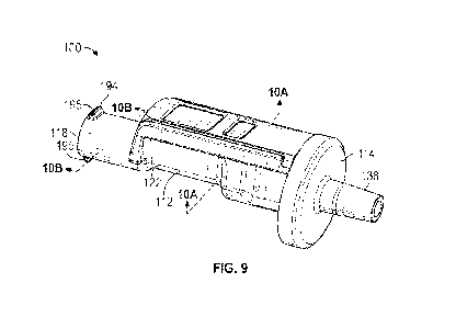
[00018] FIGS. 6 to 9represent various micro features in the area A of FIG. 5,
according to some embodiments.
[00019] FIG. 10 shows a portion of the stopper of FIGS. 3 or 4, according to
some embodiments.
[00020] FIGS. 11A to 12B represent various micro features in the area A of
FIG. 10, according to some embodiments.
[00021] FIG. 13 shows a portion of the stopper of FIGS. 3 or 4, according to
some embodiments.
[00022] FIGS. 14 to 17B represent various micro features in the area A of FIG.
13, according to some embodiments.
[00023] FIGS. 18A and 18B show a transverse cross-section of the stopper
CA 03227605 2024- 1-31
WO 2023/027727
PCT/US2021/047950
including the area "A" according to any of FIGS. 5, 10, or 13, according to
some
embodiments.
[00024] FIGS. 19A to 19E show a micro feature in the area A of any of FIGS. 5,
10, or 13, according to some embodiments.
[00025] FIG. 19F shows a displacement vs. sliding resistance relationship of a
stopper, according to some embodiments.
[00026] FIG. 20 and 21 represent systems and methods by which the system
can be used for modifying the stopper, such as according to any of those
modifications described in association with FIGS. 5 to 19E , according to some
embodiments.
[00027] FIGS. 22 to 23 represent tooling and methods by which the tooling can
be used for stopper assembly and coupling, according to some embodiments.
[00028] FIGS. 24 to 33 represent micro feature arrangements and
configurations, such as for those of FIGS. 6 to 13 and 15 to 18, according to
some
embodiments.
[00029] FIGS. 34A to 34E are illustrative of some methods of assembling the
injector device of FIGS. 1 or 2õ according to some embodiments.
DETAILED DESCRIPTION
Definitions and Terminology
[00030] This disclosure is not meant to be read in a restrictive manner. For
example, the terminology used in the application should be read broadly in the
context of the meaning those in the field would attribute such terminology.
[00031] The use of headings is provided for ease of review of the description
only, and are not meant to segregate or otherwise designate that concepts
under
one heading are inapplicable or otherwise unrelated to concepts under another
heading. In fact, the opposite is intended and the description is meant to be
read
and interpreted as a whole, with various features and aspects of certain
embodiments being applicable across and applicable to the various other
embodiments described herein.
[00032] With respect to terminology of inexactitude, the terms "about" and
"approximately" may be used, interchangeably, to refer to a measurement that
includes the stated measurement and that also includes any measurements that
are
reasonably close to the stated measurement. Measurements that are reasonably
6
CA 03227605 2024- 1-31
WO 2023/027727
PCT/US2021/047950
close to the stated measurement deviate from the stated measurement by a
reasonably small amount as understood and readily ascertained by individuals
having ordinary skill in the relevant arts. Such deviations may be
attributable to
measurement error, differences in measurement and/or manufacturing equipment
calibration, human error in reading and/or setting measurements, minor
adjustments
made to optimize performance and/or structural parameters in view of
differences in
measurements associated with other components, particular implementation
scenarios, imprecise adjustment and/or manipulation of objects by a person or
machine, and/or the like, for example. In the event it is determined that
individuals
having ordinary skill in the relevant arts would not readily ascertain values
for such
reasonably small differences, the terms "about" and "approximately" can be
understood to mean plus or minus 10% of the stated value.
[00033] As used herein, the terminology "activatable by an energy source" and
its analogs refer to a change of state of a material, such as a change in
physical
and/or chemical state. One example of activation by an energy source includes
a
marked (i.e., clearly evident) change from a solid form (or more solid form)
to a liquid
form (or more liquid form). Another example of activation by an energy source
includes exhibiting a marked (i.e., clearly evident) change in cross-linking
or
molecular weight (e.g., via cross-linking or chain scission) through exposure
to an
energy source. For reference, as used herein, "energy source" refers to
sources of
any of a variety of types of energy, including thermal, laser, radiofrequency
(RF),
microwave, ultraviolet, radiant, ultrasound, and others.
[00034] As used herein, the terms "barrier," "barrier construct," or the like
refer
to material that blocks or hinders interaction between one component (e.g., a
stopper
body) and another (e.g., a barrel and/or the contents of a barrel).
[00035] As used herein, the terms "elastic" and "elastomeric" refer to a
material property understood with reference to stoppers employed in injector
devices
(e.g., in FDA-approved applications) and relates to the tendency of a material
to
spontaneously revert back, or recover, toward its pre-deformation shape after
being
dimensionally deformed (e.g., contracted, dilated, distorted, or the like).
[00036] As used herein, the term "injector device" is meant to be inclusive of
any of a variety devices that include a stopper received in a barrel and an
actuation
mechanism configured to displace the stopper within the barrel to eject, or
deliver
contents held in the barrel from within the barrel. Examples of injector
devices
7
CA 03227605 2024- 1-31
WO 2023/027727
PCT/US2021/047950
include syringes, auto-injectors, and pens.
[00037] As used herein, the term ¨macro feature" (e.g., as in "macro rib" or
"macro groove") is meant to denote a stopper rib or groove feature, the
contours of
which are visible with the naked eye, or a stopper feature that exhibits a
height that
is two or more times the thickness of the barrier of the stopper.
[00038] As used herein the term "micro feature" (e.g., such as a micro rib,
micro groove, or micro void) is meant to denote a stopper feature (whether a
surface
feature or subsurface feature), the contours of which are not visible with the
naked
eye (though the general existence of the feature may itself be appreciable).
For
example, a micro feature would include a micro rib or micro groove feature of
a
stopper that is located on or in a macro rib or macro groove.
[00039] As used herein, the term "multi-layer barrier" refers to a barrier
construct that has a plurality of layers of material, at least portions of
which are
arranged in a superimposed fashion one over the other (a parallel
arrangement), or
in some cases, one adjacent the other (a series arrangement). A multi-layer
construct may have thicknesses or layers of material with relatively sharp,
distinct
boundaries, or may have blended or more gradual transition boundaries
therebetween.
[00040] As used herein, the term "multi-zone barrier" refers to a barrier
construct that has a plurality of zones, or sections having different material
properties. A multi-zone construct may have zones, or sections separated by
relatively sharp, distinct boundaries, or may have blended or gradual
boundaries.
Some examples of multi-zone barriers include distinct layers arranged in
parallel or
in series, such that a multi-layer barrier also defines a multi-zone barrier.
Other
examples may include a single layer that is modified to define multiple zones.
[00041]
As used herein, the term "oscillate" and the like (e.g., "oscillation") is
meant to denote motion that alternates in direction at a frequency that may be
constant or varying.
[00042] As used herein, the term "proximal" means closer to the operator end
of a device (e.g., plunger end) while the term distal means further away from
the
operator than proximal (e.g., piercing element end).
[00043] As used herein, the term "rotate" and the like (e.g., "rotation") is
meant
to denote circumferentially-oriented motion.
[00044] As used herein, the term "sealing surface" is meant to denote a
8
CA 03227605 2024- 1-31
WO 2023/027727
PCT/US2021/047950
feature that maintains a liquid-tight seal (e.g., in storage and/or in use).
[00045] As used herein, the terms "silicone" and "silicone oil" may be used
interchangeably herein.
[00046] As used herein, the term "substantially free" is meant to denote an
unquantifiable or trace amount of the identified substance (e.g., silicone,
silicone oil,
or other lubricant), or that there is not any amount intentionally added to
the system
(e.g., no silicone oil intentionally added to an injector device, such as the
barrel or
stopper).
[00047] As used herein, the term "vibrate" (e.g., "vibration") is meant to
denote
motion that alternates having an acceleration that alternates in direction at
a
frequency that may be constant or varying.
[00048] As used herein, the term "wiper" is meant to refer to an element,
sometimes referred to as a "wiper element" that is mobile (e.g., flexible or
bendable)
and configured to rub against a surface.
Description of Various Embodiments
[00049] Persons skilled in the art will readily appreciate that
various aspects of
the present disclosure can be realized by any number of methods and
apparatuses
configured to perform the intended functions. It should also be noted that the
accompanying drawing figures referred to herein are not necessarily drawn to
scale,
but may be exaggerated to illustrate various aspects of the present
disclosure, and in
that regard, the drawing figures should not be construed as limiting.
[00050] The present disclosure is directed to injector devices (e.g.,
syringes,
auto-injectors, and pens) that include a stopper at least partially covered
with a
fluoropolymer or non-fluoropolymer film or fluoropolymer or non-fluoropolymer
laminate, a barrel, and a plunger rod or actuation mechanism to displace the
stopper
within the barrel.
[00051] Various aspects of this description relate to a barrier of the stopper
that has at least one micro feature formed by activating the barrier with an
energy
source (e.g., a laser). For example, the barrier 242 may include multiple
layers, or
be a multi-layer barrier, where one layer (or layers) is configured to be more
reactive
to the energy source than another layer (or other layers) of the construct.
And, in
various embodiments that will also be subsequently described, one or more
micro
features may be formed prior to coupling the barrier to the body of the
stopper, after
9
CA 03227605 2024- 1-31
WO 2023/027727
PCT/US2021/047950
coupling the barrier to the body but before inserting the stopper into the
barrel,
and/or after coupling the barrier to the body but before inserting the stopper
into the
barrel 20. Various advantages may be realized leveraging such features,
including
more efficient and/or higher yield manufacturing, reduced contamination and/or
particulate generation, enhanced sealing, or others. For example, it may be
advantageous to form such micro features on the inner surface of the barrier
(e.g., at
a location corresponding to a macro or micro rib feature, or a macro groove or
micro
groove feature) in order to help permit the outer surface of the barrier to
achieve a
tight radius of curvature without associated wrinkling effects during
compression of
the stopper.
Injector Device Concepts
[00052]
In use, the injector devices may be employed for storing (e.g., short
term or long term) and delivering a fluid, which is typically a therapeutic or
other
substance delivered to a patient for medical use. In some embodiments, such
injector devices may be pre-filled with a therapeutic (e.g., as a pre-filled
syringe) in
advance of the planned use of the injector device to deliver the therapeutic
to a
patient. The injector devices may contain a therapeutic that treats diseases,
such
as, but not limited to, ocular disease (e.g., macular degeneration and
glaucoma) or
diabetes. Non-limiting examples of potential therapeutics are subsequently
described. Advantageously, in various embodiments, the stoppers and barrels do
not contain silicone, or silicone oil. For example, the barrels and stoppers
in the
injector devices described herein may be free or substantially free of
silicone and
silicone oil (or other liquid lubricant), according to various embodiments. In
some
instances, the stoppers and barrels do not contain any substantial amount, or
are
substantially free of any other liquid lubricant (excluding, of course,
therapeutic
substances in the injector device that are in liquid form, and thus
lubricating
themselves to at least some extent).
[00053] FIG. 1 depicts an injector device 10 in the form of a syringe,
according
to some embodiments. As shown, the injector device 10 includes a barrel 20, a
piercing element 30, and a stopper 40 received in the barrel 20 and
operatively
coupled to an actuation mechanism 50 (e.g., a plunger rod as shown).
[00054] As shown, the barrel 20 has a wall 118 and extends between a
proximal end 120 and a distal end 122. The barrel 20 has an inner surface 124
and
CA 03227605 2024- 1-31
WO 2023/027727
PCT/US2021/047950
an outer surface 126 that are each defined by the wall 118 of the barrel 20,
the inner
surface bounding a receiving chamber 128 defined by the barrel 20. As shown,
the
proximal end 120 of the barrel 20 may also include a flange that may be used
as a
finger stopper or handle to assist a user in pressing and pulling the
actuation
mechanism 50.
[00055] The piercing element 30 may include a sharply pointed needle
cannulae, or a blunt-ended cannula, such as those employed with "needleless"
systems. For ease of illustration, the piercing element 30 is depicted as a
sharply
pointed, elongate needle cannula with a sharply pointed distal end. As shown,
the
piercing element 30 is coupled with the distal end 122 of the barrel 20.
[00056] The stopper 40 is configured to be slidably received in the barrel 20,
and to seal with the inner surface 124 of the barrel 20. More specifically,
the stopper
40 is configured to be actuated within the barrel 20 by the actuation
mechanism 50
to pressurize and expel contents of the receiving chamber 128 from the barrel
20
through the piercing element 30.
[00057] The actuation mechanism 50 has a distal end 152 and a proximal end
154, where the distal end 152 is operatively coupled to the stopper 40, for
example
being fastened, integrally formed with, or otherwise associated with the
stopper 40 in
such a manner that the actuation mechanism 50 is configured to displace the
stopper 40 within the barrel 20 in a longitudinal (or other) direction.
[00058] FIG. 2 depicts an injector device 100 in the form of an auto-injector,
according to some embodiments, in which the barrel 20, the stopper 40 and the
actuation mechanism 50 (also described as an injection member in association
with
the injector device 100) may be similarly configured and employed. The
actuation
mechanism 50 of the injector device 100 may be employ, or exhibit a variable
actuation force that is applied to the stopper 40. For example, the actuation
mechanism 50 may include one or more biasing members (e.g., springs) and other
features for achieving such functionality. Various other components of the
injector
device 100 are substantially similarly to those of the injector device 10, as
would be
understood by those in the relevant field of practice. For purposes of this
description, the various features of the stopper 40 described herein are
applicable
whether utilized in the configuration of injector device 10 or that of the
injector device
100. In broader terms, the concepts described herein with respect to barrel 20
and
stopper 40 may be implemented in any of a variety of injector device
configurations.
11
CA 03227605 2024- 1-31
WO 2023/027727
PCT/US2021/047950
[00059] The injector devices 10, 100 may include a material 60 in the
receiving chamber 128 of barrel 20. In some examples, the material 60 is
deposited
or otherwise positioned in the chamber at a manufacturing site, or a site that
is
remote from the treatment site or site at which the injector device 10, 100 is
to be
employed by an end user (e.g., at a clinical site). In such cases, the
injector device
10, 100 may be referred to as being "pre-filled" (e.g., in the example of the
injector
device 10, a prefilled syringe). The material 60 may be a predetermined amount
(e.g., one or more doses) of a pharmaceutical composition. Some examples of
suitable pharmaceutical compositions are subsequently described. However, it
should be understood that the material 60 could be any type of liquid or
material
capable of being expelled from a syringe, or the material 60 may be all
together
absent from the receiving chamber, such as in an unfilled syringe. In such
examples, the injector devices 10, 100 may be filled at or near a treatment
site (e.g.,
also described as "charging" the injector device).
[00060] FIGS. 3 and 4 are plan, or front views of example configurations of
the
stopper 40, with a right half of the stopper 40 illustrated in section in the
configuration
of FIG. 3 and a left half of the stopper 40 illustrated in section in the
configuration of
FIG. 4.
[00061] As shown in each of the configurations of FIG. 3 and FIG. 4, the
stopper 40 includes a body 240 made of an elastic material, and a barrier 242,
such
as a barrier film, provided on the body 240. The stopper 40 has an outer side
244, a
longitudinal axis X, and a height along the longitudinal axis X. The stopper
40
extends between a leading face 246 and a trailing face 248. As shown, the
barrier
242 may extend along a portion of (including an entirety of) the outer side
244 and/or
the leading face 246. If desired, the barrier 242 may also extend along a
portion of
(including an entirety of) the trailing face 248.
[00062] In some embodiments, the body 240 provides a desired degree of
resilient compliance to the stopper 40. For example, the body 240 may be
compressed upon insertion of the stopper 40 into the barrel 20 so that the
stopper 40
positively engages with the barrel 20. Suitable materials for the body 240 are
described further below.
[00063] In various examples, the barrier 242 provided on the body 240 is
configured to inhibit migration of substances from (or to) the body 240
through the
barrier 242, reduce sliding and/or static friction between the stopper 40 and
the
12
CA 03227605 2024- 1-31
WO 2023/027727
PCT/US2021/047950
barrel 20, and/or to enhance sealing between the stopper 40 and the barrel 20.
Such features are referred to in the exemplary sense, and are not meant to be
an
exclusive list. The barrier 242 may be a single layer, or multiple layers. The
barrier
242 may be constructed with multiple layers that have unique properties from
one
another and/or the barrier may include multiple layers with similar properties
that are
fused or otherwise coupled to form a more homogenous construct with more
homogenous properties from layer-to-layer. The barrier 242 may also include
composite materials (e.g., a matrix film material and a filler) serving as one
or more
layers of the barrier 242. Suitable materials for the barrier 242 are
described further
below.
[00064] As shown in each of the configurations of FIGS. 3 and 4, the stopper
40 has a short, cylindrical shape, with the leading face 246 being defined by
a
conical end of the stopper 40. As shown, the conical end can project away from
the
longitudinal axis X to define an obtuse angle. In examples where the actuation
mechanism 50 is coupled to the stopper 40 using a threaded fastening
arrangement,
the stopper 40 may include an axial recess 250 in the trailing face 248 with
female
threading.
[00065] As shown, the outer side 244 of stopper 40 may define one or more
ribs 300, also described as macro ribs, such as one or more circumferentially
extending annular ribs 300 and/or one or more grooves 310, also described as
macro grooves 310, such as one or more circumferentially extending annular
grooves 310. In operation, one or more of the ribs 300 are configured to
engage
inner surface 124 (FIGS. 1 and 2) of the barrel 20 in sliding contact. The
stopper 40
may be configured to achieve container closure integrity with high levels of
gas (e.g.,
air) and liquid impermeability while also maintaining one or more of:
acceptably low
break loose force, low average glide force, and low glide force variation.
[00066] The ribs 300 can be structured in any number of configurations. For
example, only the distalmost or leading rib may have a sealing surface. It is
to be
appreciated that the quality of a seal thus formed may be assessed by any
number
of methods familiar to one skilled in the art (e.g. helium leak testing). In
some
embodiments, multiple ribs 300 may have a sealing surface. In one or more
embodiment, all of the ribs 300 having a sealing surface may have a same
predefined outer diameter (e.g., measured from an apex of the respective rib
with the
stopper 40 in a non-compressed state). In other embodiments, each rib 300
having a
13
CA 03227605 2024- 1-31
WO 2023/027727
PCT/US2021/047950
sealing surface may have its own predefined outer diameter. For example, a
distal or
leading rib may have a predefined outer diameter and a proximal or trailing
rib may
have a predefined outer diameter that is between about 75% and about 99.9% of
the
predefined outer diameter of the distal or leading rib. Other types of rib
arrangements
are contemplated, such as, for example having three ribs with sealing
surfaces,
without departing from the spirit and scope of the present disclosure.
[00067] Although three ribs 300 are shown in FIGS. 3 and 4, it should be any
number of ribs (e.g., one, two, four, ten, and so forth) are contemplated. As
shown,
the ribs 300 include a leading rib 300A having a sealing surface 320A (also
described as a sliding contact portion 320A) configured to be in sliding
contact with
the inner surface 124 of the barrel 20. As shown in FIG. 3, one or more of the
ribs
300 optionally has a flattened profile (e.g., the leading rib 300A) in which
the sealing
surface (e.g.., the sealing surface 320A) may be somewhat flattened, and have
a
width that is 1 to 25% of the length of the outer side 244 of the stopper 40.
As
shown in FIG. 4, one or more of the ribs 300 (e.g., the leading rib 300A)
optionally
has an outwardly convex shape, where the sealing surface (e.g., the sealing
surface
320A) has a relative narrower profile. As shown in FIGS. 3 and 4, the ribs 300
also
include an intermediate rib 300B and a trailing rib 300C. As shown, the
intermediate
rib 300B and the trailing rib 300C optionally have an outwardly convex shape
as
seen in section. Each of the intermediate rib 300B and trailing rib 300C
optionally
have sealing surfaces 320B, 320C, respectively, that are configured to be in
sliding
contact with the inner surface 124 of the barrel 20. Where one or more of the
ribs
300 have an outwardly convex shape, the corresponding sealing surfaces may
have
relatively small widths as measured along the longitudinal axis X of the
stopper 40.
Depending upon configuration, each of the sealing surfaces 320B, 320C (also
described as sliding contact portions 320B, 320C) may have widths that are
greater
than 0% and up to 15% of the length of the outer side 244 of the stopper 40.
[00068] As shown in FIGS. 3 and 4, the outer side 244 of the stopper 40 may
include one or more defects 900, such as wrinkles 362 and scratches 364
(examples
of defects 900 in the form of debris can be found and described in association
with
FIG. 16A). The various defects 900, such as the wrinkles 362 and/or scratches
364
may be oriented longitudinally, circumferentially, or both (e.g., helically).
The defects
900 may be relatively linear, curved, or both. The defects may be located at
any
location on the stopper 40, but may be particularly prevalent on the ribs 300
and the
14
CA 03227605 2024- 1-31
WO 2023/027727
PCT/US2021/047950
associated sealing surfaces 320, as well as on or along one or more micro
features
400, such as those subsequently described. These defects may be formed at any
point in the manufacturing process, including when the stopper 40 is first
formed
(e.g., when the barrier 242 is attached to the body 240) or during the process
of
installing the stopper 40 into the barrel 20. For example, the wrinkles 362
may be
formed when the stopper is diametrically compressed. And, the scratches 364
may
be formed when the stopper 40 is slid against the barrel 20 or another tubular
member utilized during the assembly process, for example.
Micro Feature Concepts
[00069] As designated in FIGS. 3 and 4, the stopper 40 includes one or more
micro features 400 located at one or more of the ribs 300, such as at the
sliding
contact portion 320A of the leading rib 300A. In some examples, the one or
more
micro features 400 include one or more micro grooves and/or micro ribs. In
some
examples, the micro feature 400 has a width and a depth, where depth is the
amount
of projection in the case of a micro rib and the amount of recess in the case
of a
micro groove. In some embodiments, one or both of the width and the depth are
not
greater than 200 pm, not greater than 100 pm, not greater than 50 pm, not
greater
than 10 pm, or not greater than 5 pm for example, though a variety of
dimensions
are contemplated. Note that each of the foregoing "not greater than" ranges
includes a value greater than "zero".
[00070] FIG. 5 is representative of an enlarged, sectional view of one or more
portions of the stopper 40 along the outer side 244 of the stopper 40 (e.g.,
at one of
the ribs 300). FIG. 6 to 9 represent various micro features (micro grooves /
micro
voids) included in the area "A" noted on FIG. 5 that are formed into the
barrier 242.
Although the body 240 and the barrier 242 are shown with straight edges in
FIGS. 5-
9 for ease of illustration, it should be understood that some degree of
curvature may
be exhibited (e.g., convex inward or outward) if the area shown corresponds to
a
curved portion of the stopper 40 (e.g., on one of the ribs 300).
[00071] With the foregoing in mind, FIG. 5 shows a section of the body 240
and barrier 242 of the stopper 40, along with the barrel 20, where the outer
side 244
of the stopper 40 engages with the inner surface 124 of the barrel 20,
according to
some embodiments. As shown, the barrier 242 includes a plurality of layers, or
is a
multi-layer barrier including a first layer 402 of a first material and a
second layer 404
CA 03227605 2024- 1-31
WO 2023/027727
PCT/US2021/047950
of a second material. The barrier 242 may have any of a variety of
thicknesses,
such as between 1 pm and 200 pm.
[00072] As shown, the first layer 402 may be positioned under the second
layer 404. Although two layers are generally illustrated, it should be
understood that
any number of layers are contemplated. As shown, the first layer 402 has an
inner
surface 410 facing toward the body 240 of the stopper 40 and an outer surface
412
facing toward the second layer 404. The second layer 404, in turn, includes an
inner
surface 420 facing toward the first layer 402 and an outer surface 422 facing
away
from the body 240. In various examples, the inner surface 410 of the first
layer 402
is coupled (e.g., bonded, adhered, fastened, or otherwise coupled) to the body
240.
And, in turn, the inner surface 420 of the second layer 404 is coupled (e.g.,
bonded,
adhered, fastened, or otherwise coupled) to the first layer 402. In some
embodiments, the first layer 402 can be referred to as an "inner layer" and
the
second layer 404 can be referred to as an "outer layer" of the barrier 242,
although
either of the first layer 402 and/or the second layer 404 may be an
intermediate, or
buried layer positioned between one or more other layer(s) of the barrier 242.
[00073]
In various examples, one of the plurality of layers (e.g., the first layer
402) may include a first material that is more activatable by an energy source
than a
second material of another of the plurality of layers (e.g., the second layer
404). In
particular, this feature of one layer being more activatable by an energy
source than
another may be leveraged to preferentially form a variety of micro features
400 in the
barrier 242 at a variety of locations.
[00074] A variety of materials are contemplated for each layer of the barrier
242, including those separately described. For example, the first material
and/or the
second material may include a fluoropolymer (e.g., polytetrafluoroethylene
(FIFE) or
expanded PTFE (ePTFE)). In some examples, the first layer 402 is microporous
and
defines a first porosity and the second layer 404 has a lower porosity than
the first
layer, and, optionally, the second layer 404 is characterized by a higher melt
temperature than the first layer 402. If desired, the second layer 404 may be
characterized by a higher dimensional stability than the first layer 402. At
least one
of the first material of the first layer 402 and the second material of the
second layer
404 may include a thermoplastic material. If desired, the first material of
the first
layer 402 may include a filler configured to increase absorption of light
energy and/or
radiofrequency energy of the first material. And, the filler may include at
least one of
16
CA 03227605 2024- 1-31
WO 2023/027727
PCT/US2021/047950
fluorinated ethylene propylene (FEP) and ethylene tetrafluoroethylene (ETFE),
for
example.
[00075] Although FIGS. 6-9 each show a set of micro feature examples (e.g.,
three in the case of FIG. 6), it should be understood that not all examples
need be
present together, and also that any of the examples may be combined with
various
of the other examples of micro features shown and described in association
with
other Figures. Example methods of forming such features would include
directing an
energy source (see, e.g., FIGS. 20 and 21 and associated description) through
one
layer (e.g., the second layer 404) into the other layer (e.g., the first layer
402) to
activate a portion of the other layer (e.g., reflow, ablate, heat, anneal,
sinter,
recrystallize, coalesce, chemically react, degrade, decompose, vaporize, cut,
melt, or
evaporate) to form the one or more micro features 400. For example, in the
case of
laser energy, the second layer 404 may be sufficiently transmissive to the
laser to
permit the laser to pass through the second layer 404 without activating the
second
layer 404. In turn, the first layer 402 may be relatively more absorptive to
the laser
energy, and thus more reactive to the laser energy. The micro features 400 be
formed as a discrete volume, a continuous, annular feature extending around
the
stopper, and/or a series or pattern of discrete volumes (see, e.g., FIGS. 24-
33 and
associated description).
[00076] Following formation of the various micro features (e.g.,
micro voids,
micro grooves, or micro ribs) at or near the particular microfeature 400 the
barrier
242 generally, and the first layer 402 and/or second layer 404 more
specifically, may
exhibit relatively different physical properties than surrounding portions of
the barrier
242, such as one or more of: increased compliance in the case of micro voids
or
micro grooves; reduced compression resistance in the case of micro voids or
micro
grooves; increased compression resistance in the case of micro ribs, reduced
thickness in the case of micro voids or micro grooves; increased thickness in
the
case of micro ribs, or reduced tensile strength in the case of micro voids or
micro
grooves. Such characteristics may be advantageous in reducing an effective
sealing
surface area of a rib 300 (e.g., to optimize the relationship between
increased
sealing force and reduced sliding resistance of the macro rib), creating a
preferential
failure line for the barrier 242 (e.g., to pre-select a more desirable area
for the barrier
to tear or fail to avoid contamination of the contents of injector device 10
and/or seal
failure), to fill one or more voids or defects between the barrel 20 and the
stopper 40
17
CA 03227605 2024- 1-31
WO 2023/027727
PCT/US2021/047950
or other advantages in performance and reliability.
[00077] In view of the foregoing, various aspects of the
disclosure relate to the
stopper of the injector device 10 having an outer side 244 configured for
engagement with the inner surface 124 of an injector device barrel 20. The
stopper
40 includes the body 240, for example formed of an elastomeric material, and
the
barrier 242 being coupled to the body 240. The barrier 242 has the inner
surface
410 oriented toward the body 240 and an outer surface 422 oriented away from
the
body 240. The barrier 242 includes the first layer 402 of a first material and
the
second layer 404 of a second material. The first layer 402 is configured to be
activatable by an energy source and the second layer 404 is configured to be
less
activatable by the energy source than the first layer 402. The barrier 242 has
the
one or more micro features 400 formed by activating the first layer with the
energy
source, the one or more micro features 400 including one or both of: a micro
groove
extending at least partially along the outer side 244 of the stopper 40 and/or
a micro
rib extending at least partially along the outer side 244 of the stopper 40.
[00078] With the foregoing in mind, FIG. 6 shows a first set of examples of
potential micro features 400 formed in the first layer 402 of the barrier 242
using an
energy source where the first layer 402 is more activatable by the energy
source
than the second layer.
[00079] As shown in FIG. 6, the one or more micro features 400 may include a
buried micro groove 400A, or micro void 400A extending from the inner surface
410
partially through the thickness of the first layer 402. In order to initiate
activation
toward the inner surface 410 of the first layer 402, the energy source could
be
focused (e.g., by directing two separately angled "beams" of the energy
source)
toward the inner surface 410 of the first layer 402. As another example, the
micro
groove 400A may be formed by directing the energy source at the inner surface
410
of the first layer 402 prior to coupling the barrier 242 to the body 240.
[00080] FIG. 6 shows another example of a microfeature 400 in the form of a
micro groove 400B or micro void 400B extending from the outer surface 412 of
the
first layer 402 partially through the thickness of the first layer 402. Again,
energy
could be directed through the second layer 404 into the first layer 402 to
activate a
portion of the first layer 402 (e.g., reflow, ablate, melt, heat, anneal,
sinter,
recrystallize, coalesce, chemically react, degrade, decompose, vaporize, cut,
or
evaporate) to form the micro groove 400B.
18
CA 03227605 2024- 1-31
WO 2023/027727
PCT/US2021/047950
[00081] FIG. 6 shows still another example of a microfeature 400 in the form
of a micro groove 400C or micro void 400C extending from the inner surface 410
to
the outer surface 412 of the first layer 402 through the thickness of the
first layer
402. As previously described, energy could be directed through the second
layer
404 into the first layer 402 to activate a portion of the first layer 402
(e.g., reflow,
ablate, melt, heat, anneal, sinter, recrystallize, coalesce, chemically react,
degrade,
decompose, vaporize, cut, or evaporate) to form the micro groove 400B or the
micro
groove 400A may be formed by directing the energy source at the inner surface
410
of the first layer 402 prior to coupling the barrier 242 to the body 240.
[00082] FIG. 7 shows a second set of examples of potential micro features
400 formed in the second layer 404 of the barrier 242 using an energy source
where
the second layer 404 is more activatable by the energy source than the second
layer.
[00083] As shown in FIG. 7, the one or more micro features 400 may include a
buried micro groove 400D, or micro void 400D extending from the inner surface
420
partially through the thickness of the second layer 404. In order to initiate
activation
toward the inner surface 420 of the second layer 404, the energy source could
be
focused (e.g., by directing two separately angled "beams" of the energy
source)
toward the inner surface 420 of the second layer 404. As another example, the
micro groove 400D may be formed by directing the energy source at the inner
surface 410 of the first layer 402 and through the first layer 402 into the
second layer
404 prior to coupling the barrier 242 to the body 240.
[00084] FIG. 7 shows another example of a microfeature 400 in the form of a
micro groove 400E or micro void 400E extending from the outer surface 422 of
the
second layer 404 partially through the thickness of the second layer 404.
Again,
energy could be directed at the second layer 404 or through the first layer
402 into
the second layer 404 prior to attachment of the barrier 242 to the body 240 to
activate a portion of the second layer 404 (e.g., reflow, ablate, melt, heat,
anneal,
sinter, recrystallize, coalesce, chemically react, degrade, decompose,
vaporize, cut,
or evaporate) to form the micro groove 400E.
[00085] FIG. 7 shows still another example of a microfeature 400 in the form
of a micro groove 400F or micro void 400F extending from the inner surface 420
to
the outer surface 422 of the second layer 404 through the thickness of the
second
layer 404. As previously described, energy could be directed at the second
layer
19
CA 03227605 2024- 1-31
WO 2023/027727
PCT/US2021/047950
404 or through the first layer 402 into the second layer 404 to activate a
portion of
the second layer 404 (e.g., reflow, ablate, melt, heat, anneal, sinter,
recrystallize,
coalesce, chemically react, degrade, decompose, vaporize, cut, or evaporate)
to
form the micro groove 400F.
[00086] FIG. 8 shows a third set of examples of potential micro features 400
formed in the second layer 404 and/or the first layer 402 of the barrier 242
using an
energy source where one of the first layer 402 and the second layer 404 is
more
activatable by the energy source than the other.
[00087] As shown in FIG. 8, the one or more micro features 400 may include a
buried micro groove 400G, or micro void 400G extending between the inner
surface
420 and outer surface 422 within the thickness of the second layer 404. In
order to
initiate activation within the second layer 404, the energy source could be
focused
(e.g., by directing two separately angled "beams" of the energy source) toward
the
inner surface 420 of the second layer 404 or include a localized filler
material that is
more absorptive to laser energy than surrounding portions of the second layer
404
(e.g., a pigment, or other material to enhance energy absorption). For
example, the
barrier 242 may be a multi-zone barrier including a first zone 400Z1 having a
first
material property (e.g., activatability or responsiveness to an energy source)
and an
activatable zone 400Z2 having a second material property (e.g., higher
activatability
or responsiveness to the energy source relative to the first zone. For
example, in the
case of laser energy, the first zone 400Z1 may have a lower light absorption
characteristic (e.g., a lower amount or different pigment to have higher
transmissivity) than the activatable zone 400Z2. As another example, the micro
groove 400G may additionally or alternatively be formed by directing the
energy
source at the inner surface 410 of the first layer 402 and through the first
layer 402
into the second layer 404 prior to coupling the barrier 242 to the body 240.
[00088] As shown in FIG. 8, the one or more micro features 400 may include a
buried micro groove 400H, or micro void 400H extending between the inner
surface
410 and outer surface 412 within the thickness of the first layer 402. In
order to
initiate activation within the first layer 402, the energy source could be
focused (e.g.,
by directing two separately angled "beams" of the energy source) toward the
inner
surface 410 of the first layer 402 or include a localized filler material that
is more
absorptive to laser energy than surrounding portions of the first layer 402
(e.g., a
pigment, or other material to enhance energy absorption). As another example,
a
CA 03227605 2024- 1-31
WO 2023/027727
PCT/US2021/047950
buried micro groove 400H may be formed by directing the energy source at the
inner
surface 410 of the first layer 402 prior to coupling the barrier 242 to the
body 240.
[00089] FIG. 9 shows a fourth set of examples of potential micro features 400
formed in the second layer 404 and/or the first layer 402 of the barrier 242
using an
energy source where one of the first layer 402 and the second layer 404 is
more
activatable by the energy source than the other.
[00090] As shown in FIG. 9, the one or more micro features 400 may include a
buried micro groove 400J, or micro void 400J extending between the inner
surface
410 of the first layer into the second layer 404, but terminating prior to
reaching the
outer surface 422 of the second layer 404. Such a feature may result where the
first
layer 402 is more activatable by an energy source than the second layer, and
as a
result the micro groove 400J only forms partially through the second layer
404. The
micro groove 400J may be formed using methods as previously described.
[00091] Similarly, a micro groove 400K, or micro void 400K may be formed
from the outer surface 422 of the second layer 404, through the thickness of
the
second layer 404 and partially into the first layer 402 through the outer
surface 412
of the fist layer to terminate within the thickness of the first layer 402.
Such a feature
may result where the first layer 402 is more activatable by an energy source
than the
first layer, and as a result the micro groove 400K only forms partially
through the first
layer 402. The micro groove 400J may be formed using methods as previously
described.
[00092] In some embodiments, more than one of the layers of the barrier 242
may be activatable by an energy source, with one or more of the micro features
400
formed through multiple layers. As shown in FIG. 9, the one or more micro
features
400 may include a micro groove 400L, or micro void 400L extending between the
outer surface 422 of the first layer into and through the second layer 404 to
the inner
surface 410 of the second layer 404. Such a feature may result where the first
and
second layers 402, 404 are activatable by an energy source, and as a result
the
micro groove 400L forms through the first layer 402 and the second layer 404.
The
micro groove 400L may be formed using any of the methods previously described.
[00093] FIGS. 10 to 128 show examples of how micro features 400 may be
formed in one layer (e.g., the second layer 404) through formation of
microfeature
400 in another layer (e.g., the first layer 402), and how such features may
result in
enhanced sealing with the barrel 20.
21
CA 03227605 2024- 1-31
WO 2023/027727
PCT/US2021/047950
[00094] FIG. 10 is representative of an enlarged, sectional view of one or
more portions of the stopper 40 along the outer side 244 of the stopper 40
(e.g., at
one of the ribs 300). FIG. 11 to 12B represent various micro features (micro
ribs /
micro grooves / micro voids) included in the area "A" noted on FIG. 10. As
shown in
FIG. 10, the barrier 242 optionally includes multiple layers (as designated by
the
broken line in FIG. 10), but may also be a monolithic or single layer
construction. In
various examples, a portion of the barrier 242 (e.g., the second layer 404) is
less
activatable by an energy source than another portion of the barrier 242 (e.g.,
the first
layer 402) and the one or more micro features 400 are formed by activating a
portion
(e.g., the first layer 402) of the barrier 242. In still other embodiments
(not shown),
the barrier 242 is less activatable by an energy source than the body 240 of
the
stopper 40, and the one or more micro features 400 are formed by activating
the
body 240 of the stopper 40 through the barrier 242. For the avoidance of
doubt, the
body 240 can be considered a "layer" of the stopper 40, according to some
examples.
[00095] FIG. 11A shows energy 1312 applied to the barrier 242, and FIGS.
11B and 11C are examples of micro features 400 that may be formed as a result.
As
shown, the energy 1312 is directed through the barrel 20 to the stopper 40.
[00096] FIG. 11B is illustrative how formation of a micro void 400M or micro
groove 400M in the inner surface 410 results in a micro groove 400S in the
outer
surface 422 of the barrier 242. For example, the micro groove 400M may be
formed
in the first layer 402 (e.g., using any of the techniques previously
described) resulting
in the formation of a micro groove 400S in the second layer 404. Where
present, the
first layer 402 may be more activatable or responsive to an energy source than
the
second layer 404, and the energy source may be used to form the micro groove
400M in the first layer 402. This, then, can be leveraged to form the micro
groove
400S in the second layer 404. For example, the material of the first layer 402
may
conform, or depress into the micro groove 400M to form the micro groove 400S.
Use of this feature may help ensure that the micro groove 400S can be formed
without defeating the integrity of the barrier 242, or in different terms,
without
defeating the integrity of the second layer 404 and providing a path from the
outer
side 244 of the stopper 40 to the body 240 of the stopper 40.
[00097] As shown, micro features 400, and specifically micro ribs 400P may
also be formed by portions of the barrier 242 along opposite edges of other
micro
22
CA 03227605 2024- 1-31
WO 2023/027727
PCT/US2021/047950
features 400, and specifically the micro groove 400M, by projections, or
increased
thicknesses, resulting when the micro groove 400M is formed by activating the
barrier 242 with an energy source (e.g., laser energy). For example, as a
portion of
the barrier 242 (e.g., the first layer 402) is evaporated or decomposed by the
energy
source (e.g., laser beam) using any of the methods previously described, the
evaporated or decomposed portion may be partly re-deposited along the opposite
edges of the micro groove 400M to form the micro ribs 400P.This, in turn, may
result
in formation of micro ribs 400R in another portion of the barrier 242 (e.g.,
the second
layer 404) without having to directly alter that portion of the barrier 242
(e.g., the
second layer 404) with the energy source. Such a feature may have a variety of
benefits, including the avoidance of generating free particulate, contaminants
or
byproducts of the energy activation process that could contaminate the outer
side
244 of the stopper 40, and ultimately the contents of the injector device 10.
[00098]
FIG. 11C is illustrative of formation of the micro groove 400M directly
into the outer side 244 of the barrier 242 (which may or may not include
multiple
layers) results in formation of micro ribs 400R. Again, as a portion of the
barrier 242
is evaporated or decomposed by the energy source (e.g., laser beam) using any
of
the methods previously described, the evaporated or decomposed portion may be
partly re-deposited along the opposite edges of the micro groove 400M to form
the
micro ribs 400P.
[00099] As shown in FIGS. 11A to 11C, the inner surface 124 of the barrel 20
may have defects 700 in the form of surface irregularities. The surface
irregularities
are represented generally in the Figures as a cross-hatched area. Regardless,
in
various examples, the inner surface 124 is not perfectly smooth, and may
include
micro scratches and bumps or even macro scratches and bumps or other
irregularities. As shown in FIGS. 11B and 11C, in various embodiments upon
formation of the micro features 400 (e.g., micro ribs 400R) in the outer side
244 of
the stopper 40, the barrier 242 conforms more closely to the barrel 20 by
accommodating, or better filling in, the defects 700 proximate the micro
features 400
that are formed.
[000100] In some examples, the outer side 244 of the stopper 40 includes a
polymeric material (e.g., FEP, ePTFE, PTFE, and/or another polymeric material
described herein) that forms a seal interface 702 (FIG. 10) with the barrel,
and
modifying the stopper 40 includes inducing polymeric movement of the polymeric
23
CA 03227605 2024- 1-31
WO 2023/027727
PCT/US2021/047950
material at the seal interface 702 with energy 1312. This can be true in any
of the
examples of micro feature formation, and particularly in the case of micro rib
formation. As shown in FIG. 11A, prior to such filling in, or accommodation of
the
defects 700, there may be a space 710 (represented generally in FIG. 11A), or
potential leak path 710, between the stopper 40 (the barrier 242) and the
barrel 20.
After formation of the micro features 400 (e.g., micro ribs 400R), the space
710, or
potential leak path 710, may be more effective sealed, or closed proximate the
micro
features 400. This, in turn, may result in a relatively more secure, or stable
seal
proximate the micro features 400, or in different terms, an improved seal
integrity.
[000101] Thus, by application of the energy 1312 (FIG. 11A) through the barrel
20, the stopper 40 is modified and such modification includes improving a seal
integrity of the stopper 40. Application of energy 1312 through the barrel 20
can be
achieved in a variety of manners, including those described in association
with FIG.
20, for example. In some examples, the energy 1312 is applied
circumferentially
between at least a portion of the circumference of the stopper 40 and the
barrel 20.
In such examples, the area A shown in FIGS. 11B and 11C may be representative
of
a cross-section of a seal line formed between at least a portion of the
circumference
of the stopper 40 and the barrel 20 by the energy 1312. Thus, in some
examples,
modifying the stopper 40 includes improving the seal integrity of the stopper
40 by
forming a seal line between the outer side 244 of the stopper 40 and the inner
surface 124 of the barrel 20.
[000102] FIGS. 12A and 12B show another example of a potential micro feature
400 in the form of a micro rib 400T (FIG. 12B). As shown in FIG. 12A, the
first layer
402 includes a mass of material, or activatable zone 400Za, that is configured
to
expand, or increase in volume via activation by an energy source (e.g., laser
energy). As shown in FIG. 12A, the activatable zone 400Za starts at a first
size, or
volume and following activation as shown in FIG. 12A occupies transforms into
a
second, larger size or volume in the form of activated zone 400Zb. This
expansion,
or change in volume, in turn results in deflection of the barrier 242, (e.g.,
the second
layer 404 when present, and optionally the first layer 402 when present),
resulting
formation of a micro rib 400T as shown in FIG. 12B. Although the expandable
material may be limited to a zone, the activatable zone 400Za, it is also
contemplated that the entire layer may be formed of the activatable material
and that
only a portion of the layer is activated to form the micro rib 400T, for
example.
24
CA 03227605 2024- 1-31
WO 2023/027727
PCT/US2021/047950
[000103] An example of an expandable, energy activatable material, can be
found in U.S. Pat. 5571592 to McGregor et al. The activatable zone 400Za may
include expandable thermoplastic microspheres interspersed and contained
within
the activatable zone 400Za. The use of such expandable microspheres can allow
for
(1) the introduction of unexpanded microspheres into the first layer 402; and
(2)
expansion of the microspheres within the first layer 402 to a greater
diameter. In
various examples, when subjected to heat (e.g., thermal energy through
application
of a laser or other energy source) or similar activation energy, the
microspheres
dramatically expand to many times their original size and retain such size
when the
activation energy is removed. Processes for producing such material can be
found in
U.S. Pat. 3615972 to Morehouse et al., for example.
[000104] In view of the foregoing, various examples include the stopper 40,
and
more specifically the barrier 242 defining a micro groove (e.g., any of the
micro
grooves previously described), the barrier 242 at the micro groove being
continuous
and uninterrupted, and being relatively thinner than the barrier 242 is at
surrounding
portions of the barrier 242.
[000105] The micro groove may define a discontinuous, broken, circumferential
line pattern as described in association with FIG. 27, for example. In some
examples, the barrier 242 is a multi-layer barrier (e.g., two layers or more)
in which
the first layer 402 has one or more discontinuous portions (e.g., a continuous
circumferential micro groove or a micro groove having a discontinuous,
circumferential broken line pattern as described in association with FIG. 27).
The
second layer 404 overlies the one or more discontinuous portions, such as a
micro
groove. In this manner, the second layer 404 may provide an uninterrupted
barrier
between the body 240 and the barrel 20, and its contents. In different terms,
the
second layer 404 may extend across the one or more discontinuous portions of
the
first layer 402.
[000106] The underlying, first layer 402 may be formed of a relatively higher
strength material whereas the overlying, second layer 404 may be formed of a
relatively more compliant, weaker material. In this manner, the barrier 242
may be
provided with a high degree of compliance on the outer surface while also
exhibiting
a relatively high degree of tear resistance due to the underlying, first layer
402. This
feature can then also be coupled with the ability to provide a micro groove
and/or
micro rib that is exhibited by the second layer 404 at the outer side 244
without
CA 03227605 2024- 1-31
WO 2023/027727
PCT/US2021/047950
directly forming (e.g., mechanically or energetically) the second layer 404,
creating
unwanted debris particulate (which may contaminate the barrel 20 and its
contents
and/or without unduly weakening the more compliant second layer 404 such that
it
would fail in use.
[000107] Although various examples include forming the discontinuous portion
in the underlying, first layer 402, in some examples, the second layer 404 may
have
one or more discontinuous portions and the first layer 402 may extend across
the
one or more discontinuous portions, as well as the elastomer body 21,
providing a
barrier between the outer side 244 and the body 240 (e.g., microgroove 400F in
FIG.
7). Again, the discontinuity may be defined by at least one micro groove. The
first
layer 402 may be exposed through the second layer 404 to define at least a
portion
of the outer side 244 of the stopper 40. The one or more discontinuous
portions may
result in the second layer 404 being less resistant to tearing than the first
layer 402
at the one or more discontinuous portions.
[000108] This feature of forming a micro channel in the second layer 404 while
preserving the first layer 402 may be advantageous in at least the concept
that,
again the underlying first layer may be relatively stronger than the outer
layer and
prevent tearing through both layers to expose the underlying body 240 to the
barrel
20 and its contents. For example, the first layer 402 may be formed of a
microporous layer having a greater strength than the second layer 404 where
the
first layer 402 extends across the one or more discontinuous portions. The
first layer
may include a densified fluoropolymer (e.g., having a relatively high tensile
strength),
a thermoplastic material, and/or an elastomeric material. The first layer 402
may
additionally or alternatively include a micro rib and/or a microgroove.
[000109] The discontinuous portion of the second layer 404 may include a
micro rib and/or a micro groove. In some examples, the second layer may be non-
porous. For example, the second layer 404 may be polytetrafluoroethylene
(e.g.,
skived PTFE).
[000110] As previously discussed in association with FIGS. 11B and 11C, FIG.
12B shows defects 700 in the form of surface irregularities in the barrel 20
as the
inner surface 124 is not perfectly smooth. As shown in FIG. 12B, in various
embodiments upon formation of the micro features 400 (e.g., micro rib 400T) in
the
outer side 244 of the stopper 40, the barrier 242 conforms more closely to the
barrel
20 by accommodating, or better filling in, the defects 700 proximate the micro
26
CA 03227605 2024- 1-31
WO 2023/027727
PCT/US2021/047950
features 400 (micro rib 400T) formed.
[000111] As previously referenced, the outer side 244 of the stopper 40 may
include a polymeric material (e.g., FEP, ePTFE, PTFE, and/or another polymeric
material described herein) that forms a seal interface 702 (FIG. 10) with the
barrel
20, and modifying the stopper 40 includes inducing polymeric movement of the
polymeric material at the seal interface 702 with energy 1312 (e.g., via
formation of
micro rib 400T). As shown in FIG. 12A, prior to such filling in, or
accommodation of
the defects 700, there may be a space 710, or potential leak path 710, between
the
stopper 40 (the barrier 242) and the barrel 20. And, after formation of the
micro
feature 400 (micro rib 400T), the space 710, or potential leak path 710, is
more
effective sealed, or closed proximate the micro rib 400T. This, in turn, may
result in
a relatively more secure, or stable seal proximate the micro features 400
(micro rib
400T), or in different terms, an improved seal integrity.
[000112] Thus, similarly to FIG. 11A, by application of the energy 1312 shown
in FIG. 12A through the barrel 20, the stopper 40 is modified and such
modification
includes improving a seal integrity of the stopper 40. Again, application of
energy
1312 through the barrel 20 can be achieved in a variety of manners, including
those
described in association with FIG. 20, for example. In some examples, the
energy
1312 is applied circumferentially between at least a portion of the
circumference of
the stopper 40 and the barrel 20. In such examples, the area A shown in FIGS.
12A
and 12B may be representative of a cross-section of a seal line formed between
at
least a portion of the circumference of the stopper 40 and the barrel 20 by
the energy
1312. Thus, in some examples, modifying the stopper 40 includes improving the
seal integrity of the stopper 40 by forming a seal line between the outer side
244 of
the stopper 40 and the inner surface 124 of the barrel 20.
[000113] FIG. 13 is representative of an enlarged, sectional view of one or
more portions of the stopper 40 along the outer side 244 of the stopper 40
(e.g., at
one of the ribs 300). FIGS. 14 and 15 represent various micro features (micro
ribs /
micro grooves / micro voids) included in the area "A" noted on FIG. 13. As
shown in
FIG. 13, the barrier 242 optionally includes multiple layers (as designated by
the
broken line in FIG. 13), but may also be a monolithic or single layer
construction. In
various examples, the barrier 242 is less activatable by an energy source than
the
body 240 of the stopper 40, and the one or more micro features 400 are formed
by
activating the body 240 of the stopper 40. For the avoidance of doubt, the
body 240
27
CA 03227605 2024- 1-31
WO 2023/027727
PCT/US2021/047950
can be considered a "layer" of the stopper 40.
[000114] FIGS. 14 and 15 show examples of how micro features 400 may be
formed in one layer of the stopper 40 (e.g., the body 240) through formation
of
microfeature 400 in another layer (e.g., the barrier 242). For example, as
shown in
FIG. 14, micro features 400, and specifically micro ribs 400W may be formed by
portions of the barrier 242 along opposite edges of other micro features 400,
and
specifically micro grooves 400X or micro voids 400X, by projections, or
increased
thicknesses, resulting when the micro grooves 400X are formed by activating
the
body 240 with an energy source (e.g., laser energy). For example, as a portion
of a
layer of the stopper 40 (e.g., the body 240) is evaporated or decomposed by
the
energy source (e.g., laser beam) using any of the methods previously
described, the
evaporated or decomposed portion may be partly re-deposited along the opposite
edges of the micro grooves 400X to form the micro ribs 400W. This, in turn,
may
result in formation of micro ribs 400Y and micro grooves 400Z in another layer
(e.g.,
the barrier 242) without having to directly alter the other layer (e.g., the
barrier 242)
with the energy source. Such a feature may have a variety of benefits,
including the
avoidance of generating free particulate, contaminants or byproducts of the
energy
activation process that could contaminate the outer side 244 of the stopper
40, and
ultimately the contents of the injector device 10.
[000115] FIG. 15 shows another example of a potential micro feature 400 in the
form of a micro rib 400AB. As shown in FIG. 15, a first layer of the stopper,
the
body 240, includes a mass of material, or activatable zone 400AZ, that is
configured
to expand, or increase in volume via activation by an energy source (e.g.,
laser
energy). The activatable zone 400AZ is configured to enlarge from a first
size, or
volume following activation by the energy source such that the activatable
zone
400AZ occupies a second, larger size or volume (depicted in FIG. 15). This
expansion, or change in volume, in turn results in deflection of the barrier
242,
resulting formation of a micro rib 400AB as shown in FIG. 15. Although the
expandable material may be limited to a zone, the activatable zone 400AZ, it
is also
contemplated that the entire layer may be formed of the activatable material
and that
only a portion of the layer is activated to form the micro rib 400AB.
[000116] FIGS. 14 and 15 depict barrel surface irregularities, or defects, as
previously described. As shown in FIGS. 14 and 15, where the outer side 244 of
the
stopper 40 includes a polymeric material (e.g., FEP, ePTFE, PTFE, and/or
another
28
CA 03227605 2024- 1-31
WO 2023/027727
PCT/US2021/047950
polymeric material described herein) that forms a seal interface 702 (FIG. 10)
with
the barrel 20, modifying the stopper 40 may include inducing polymeric
movement of
the polymeric material at the seal interface 702 with energy 1312 applied as
shown
in FIG. 20 for example. Such polymeric movement may result via formation of
micro
ribs 400Y, 400Z, 400AB. Prior to such filling in, or accommodation of the
defects
700, there may be space, or potential leak paths, between the stopper 40 (the
barrier
242) and the barrel 20. And, after formation of the micro feature 400 (micro
ribs
400Y, 400Z, 400AB), the space, or potential leak path, is more effective
sealed, or
closed proximate one or more of the micro ribs 400Y, 400Z, 400AB. This, in
turn,
may result in a relatively more secure, or stable seal proximate the micro
features
400 (micro ribs 400Y, 400Z, 400AB), or in different terms, an improved seal
integrity.
[000117] Thus, similarly to FIGS. 11A and 12A, by application of energy
through the barrel 20, the stopper 40 of FIGS. 14 and 15 is modified and such
modification includes improving a seal integrity of the stopper 40. Again,
application
of energy through the barrel 20 can be achieved in a variety of manners,
including
those described in association with FIG. 20, for example. In some examples,
the
energy is applied circumferentially between at least a portion of the
circumference of
the stopper 40 and the barrel 20. In such examples, the area A shown in FIGS.
14
and 15 may be representative of a cross-section of a seal line formed between
at
least a portion of the circumference of the stopper 40 and the barrel 20 by
the
energy. Thus, in some examples, modifying the stopper 40 includes improving
the
seal integrity of the stopper 40 by forming a seal line between the outer side
244 of
the stopper 40 and the inner surface 124 of the barrel 20.
[000118] FIGS. 16A to 17B represent various micro features included in the
area "A" noted on FIG. 13. In particular, FIGS. 16A to 17B illustrate
additional
mechanisms by which seal integrity between the stopper 40 and the barrel 20
may
be enhanced by delivering energy 1312 through the barrel 20 to the stopper 40
(e.g.,
as described in association with FIG. 20). As in other examples (e.g., as
described in
association with FIGS. 11B, 11C, 12B, 14, and 15), polymeric movement of a
portion
of the stopper 40 may be utilized to enhance seal integrity. Notably, this may
be
done over a relatively small area (e.g., the tip of a macro rib, such as macro
rib 300A
shown in FIGS. 3 and 4) providing a relatively small tradeoff in sliding
resistance for
enhanced seal integrity. Stated different, a thin, enhanced line of sealing
can be
created without unduly increasing resistance of the stopper to sliding within
the
29
CA 03227605 2024- 1-31
WO 2023/027727
PCT/US2021/047950
barrel 20.
[000119] As shown in FIG. 16A, the seal interface 702 between the outer side
244 of the stopper 40 and the barrel 20 may include particulate 800 (e.g.,
debris)
introduced into the seal interface 702. Such particulate may include portions
of the
stopper 40 or barrel 20 that have broken off or were loosened during
manufacturing,
or foreign matter. As shown in FIG. 16B, during application of energy 1312
through
the barrel, such particulate may be ablated, reflowed, or coalesced into the
interface
70. Clearly, a reduction in such particulate would be desirable, particularly
in
pharmaceutical applications where contamination of the barrel contents is
particularly undesirable. Also, as shown in FIG. 16B, the surface of the
stopper 40,
and in particular the barrier 242, may include one or more wrinkles or surface
defects
900. Such surface defects 900 may be created during insertion of the stopper
40
into the barrel 20, during manufacture, or otherwise. Application of energy to
the
wrinkles or surface defects 900 may result in polymeric movement of the
material of
the barrier 242, thereby smoothing out the surface defects or wrinkles and
bringing
the outer side 244 of the stopper 40 into closer conformity with the inner
surface 124
of the barrel 20. This, in turn, can be said to reduce the roughness of the
outer
surface 244 of the stopper 40. Again, the energy 1312 could be applied in a
circumferential pattern to create a seal line of enhanced seal integrity.
[000120] FIGS. 17A and 17B show a similar effect, where the surface of the
barrier 242 is reflowed, or mobilized using the energy 1312 to fill in defects
(e.g.,
scratches or grooves) in the inner surface 124 of the barrel 20. As shown in
FIG.
17A, there is a space or potential leak path 710 between the barrel 20 and the
stopper 40. Upon energization, and mobilization of the surface of the barrier
242,
the potential leak path 710 is filled, enhancing overall seal integrity. And,
similarly to
FIGS. 16A and 16B, the energy 1312 could be applied in a desired pattern
(e.g.,
circumferential) to create a desired seal line configuration (e.g., on one of
the ribs
300).
[000121] FIGS. 18A and 18B illustrate similar principals to FIGS. 16A to 17B
regarding the application of energy 1312 through the barrel 20, but along a
transverse cross-section through the injector device 10. In particular, FIGS.
18A and
186 are representative of a transverse cross-section of the injector device 10
including the area "A" designated in any of FIGS. 5, 10, and 13, for example.
FIG.
18A depicts the barrel 20, and specifically the defects 700 in the form of
surface
CA 03227605 2024- 1-31
WO 2023/027727
PCT/US2021/047950
irregularities (e.g., scratches) about the circumference of the inner surface
124 of the
barrel 20 from a longitudinal view. Also shown are wrinkles or surface defects
900 in
the outer side 244 about the circumference of the stopper 40. Also shown is
energy
1312 being applied through the barrel 20 to the stopper 40 about the
circumference
of the seal interface 702 between the barrel 20 and the stopper 40.
[000122] FIG. 18A illustrates the seal interface 702 following application of
the
energy 1312 in a circumferential pattern about the barrel 20 and stopper 40.
As
shown, the energy 1312 can induce polymeric movement of the stopper 40 (e.g.,
of
the barrier 242) causing filling of the defects 700 in the barrel 20,
smoothing of the
wrinkles or surface defects in the stopper 40, enhancement of the seal
interface 702,
and creation of a circumferential seal line corresponding to the seal
interface 702
designated in FIG. 18B.
[000123] FIGS. 19A to 19F disclose additional features optionally created by
directing energy through the barrel 20 of the stopper 40. In particular, the
surface of
stopper 40 may be modified to achieve a raised projection (e.g., micro rib)
configured
to achieve a wiper effect during displacement of the stopper 40 in the barrel
20. The
flexible surface feature for achieving the wiper effect includes a raised
projection 600
(e.g., a micro rib 400 or macro rib 300) projecting from a pocket 602. The
raised
projection 600 has a flexible body and the pocket 602 is formed by least one
void,
such as a first void 620 on a first side of the raised projection 600 and a
second void
622 on the second side of the raised projection 600. As shown in FIG. 19A,
energy
1312 is directed at the barrier 242 to form the first and second voids 620,
622 and
the resulting raised projection 600. The voids 620, 622 may be formed in a
circumferential pattern, such that the raised projection 600 extends
circumferentially
about the stopper 40 at the outer side 244.
[000124] As shown in FIG. 19B, the raised projection 600 is formed from the
material of the barrier 242 (e.g., optionally the second layer 404 where
present). As
shown, the first void 620 is bounded by the raised projection 600 and a first
edge
650 and the second void 622 is bounded by the raised projection 600 and a
second
edge 652. In various examples, the raised projection (e.g., a micro rib) may
actuate,
flex, or bend between the first and second edges 650, 652 through the sweep
angle
previously described.
[000125] As shown in FIG. 19C, the raised projection 600 has sufficient
flexibility to deflect, flex or bend (e.g., resiliently, or elastically) in a
direction parallel
31
CA 03227605 2024- 1-31
WO 2023/027727
PCT/US2021/047950
to the longitudinal axis X (FIGS. 5, 10, 13). The raised projection 600 can
deflect,
bend or flex as the stopper 40 is slid within the barrel 20 in a first
direction Y, for
example. FIG. 19B shows the raised projection 600 in an initial position in
which the
raised projection 600 resiliently compressed in engagement with the barrel 20.
At
this initial position, the raised projection 600 (e.g., micro rib 400) defines
a first seal
force or first seal pressure against the barrel 20. As shown in FIG. 19C, when
the
stopper 40 is slide in the first direction Y within the barrel 20, the raised
projection
600 (e.g., micro rib 400) deflects along a sweep angle a. In some embodiments,
as
the raised projection 600 deflects, the first seal force or first seal
pressure is reduced
to a second, lower seal force or pressure. This reduction in seal force may be
advantageous in that there may be a drop in sliding resistance, or break loose
force,
required to initiate movement of the stopper 40 within the barrel. For
example,
during displacement in the direction Y there may initially be a high sealing
force that
quickly drops as displacement is initiated and the raised projection 600
flexes. The
seal force may begin to increase again as displacement is halted, and the
raised
projection 600 is permitted to reorient in a more radial direction.
[000126] As shown in FIGS. 19D and 19E, formation of raised projections 600
does not require formation of a pocket, such as pocket 602, or substantial
removal of
any material. For example, cuts, slices or slits 604 may be formed into the
barrier
242 to form one or more raised projections 600. As shown in FIG. 19D, the
slits 604
may be formed at any of a variety of angles, including in a radial direction
as shown.
As shown in FIG. 19E, when the stopper 40 is slid in the first direction Y
within the
barrel 20, the one or more raised projection 600 (e.g., a plurality of micro
ribs 400 /
projections 600) deflects along the sweep angle a. Again, in some embodiments,
as
the raised projection(s) 600 deflect, the sliding resistance is reduced to a
second,
lower sliding resistance. As previously referenced, in some examples, the
first seal
force or first seal pressure is also reduced to a second, lower seal force or
pressure
following displacement. This reduction in sliding resistance can be
advantageous in
reducing break loose force and the force required to initiate movement of the
stopper
40 within the barrel.
[000127] FIG. 19F is illustrative of this concept of a quick drop in sliding
resistance upon displacement, according to the examples described in
association
with FIGS. 19A to 19E, for example. As shown in FIG. 19F, an initial high
sliding
resistance of the stopper 40 in the barrel 20 quickly drops as displacement is
32
CA 03227605 2024- 1-31
WO 2023/027727
PCT/US2021/047950
initiated. As shown in FIG. 19F, the sliding resistance may begin to increase
again
as displacement of the stopper 40 is halted, and the raised projection 600 is
permitted to reorient in a more radial direction.
[000128] Although previously referenced, for the avoidance of doubt the
various
multi-layer barrier configurations, including any of those described above in
association with FIGS. 5 to 19C) may include more than two layers (e.g., five
in
total). As shown, the first layer 402 and/or the second layer 404 may be at
any
position within the layers. And, there may be greater or fewer layers in
various
implementations. The first layer 402 may be an innermost layer, or a buried
layer,
for example. The second layer 404 may be an outermost layer, or a buried
layer, for
example. And, the first layer and second layers 402, 404 may be in contact, or
separated by one or more other layers.
[000129] The various micro features 400 described above may have any of a
variety of dimensions. In some examples, one or more of the micro grooves have
a
depth from 0.25 pm to 50 pm, and optionally from 0.25 pm to 0.5 pm and a width
from 0.25 pm to 50 pm, and optionally from 0.25 pm to 0.5 pm and/or one or
more
of the micro ribs has a height from 0.25 pm to 50 pm, and optionally from 0.25
pm to
0.5 pm and a width from 0.25 pm to 50 pm, and optionally from 0.25 pm to 0.5
pm.
As will be subsequently described, the micro grooves and/or micro ribs may
have
any of a variety of configurations, for example extending in a circumferential
direction, a helical direction, or even a longitudinal direction. As
illustrated above in
association with FIGS. 11 and 16, for example, one or more micro grooves may
have
a base and two sides, where one or both of the two sides defines a micro rib.
In
some embodiments, material forming the micro rib has a higher density than
material
forming the base of the micro groove. And, in some embodiments, material
forming
the micro rib has a lower density than material forming the base of the micro
groove.
[000130] Also, as described above, a portion of the stopper 40, such as the
first
layer 402 optionally includes a material configured to increase in volume upon
being
activated by the energy source, and a resulting micro rib corresponds to a
portion of
the first layer 402 that has been increased in volume by being activated by
the
energy source. And, in the case of micro channels or voids, a portion of the
stopper
40, such as the first layer 402 includes a material configured to be removed
upon
being activated by the energy source, where the micro groove corresponds to a
portion of the first layer 402 that has been removed by being activated by the
energy
33
CA 03227605 2024- 1-31
WO 2023/027727
PCT/US2021/047950
source.
Means for Application of Energy to Stopper Components
[000131] Various aspects of this disclose relate to methods for manufacturing
injector device 10, 100 including modifying the stopper 40 by directing energy
through the wall of the barrel 20 to the stopper 40. In various examples,
modifying
the stopper 40 Oincludes modifying the outer side 244 of the stopper 40, such
as by
melting a portion of the stopper 40, which may improve seal integrity of the
stopper
40 with the barrel 20. Seal integrity may be improved by reducing wrinkling in
the
outer side 244 of the stopper 40, forming a seal line between the outer side
244 of
the stopper 40 and the inner surface 124 of the barrel 20, and/or decreasing
one or
more leak paths between the stopper 40 and the barrel 20, for example. In some
examples, modifying the stopper includes modifying an activatable layer of the
stopper 40 by directing energy through the wall 118 of the barrel 20 to the
activatable
layer.
[000132] In some examples (e.g., as described in association with FIGS. 19A to
19C), modifying the stopper 40 includes decreasing sliding resistance between
the
outer side 244 of the stopper 40 and the inner surface 124 of the barrel 20.
Modifying the stopper 40 may include forming one or more micro features 400 of
the
stopper 40, or modifying one or more micro features 400 already present on the
stopper 40. By directing energy through the wall 118 of the barrel 20, a
portion of
the stopper may be at least one of reflowed, ablated, evaporated, heated,
annealed,
sintered, recrystallized, coalesced, chemically reacted, degraded, decomposed,
vaporized, or cut. For example, the outer side 244 of the stopper 40 may
include a
polymeric material that forms the seal interface with the barrel 20, and
modifying the
stopper 40 includes inducing polymeric movement of the polymeric material at
the
seal interface. For example, a portion of the stopper may be caused to melt,
reflow
and resolidify.
[000133] And, such polymeric movement may result in at least one of filling
one
or more defects of the inner surface of the barrel and/or smoothing one or
more
defects of the outer side of the stopper (e.g., such as wrinkles). The energy
applied
may take a variety of forms, such as laser energy, RE energy, induction
energy,
electron beam energy, and thermal energy. Depending on the energy to be
applied
to the stopper through the wall 118 of the barrel 20, the wall 118 of the
barrel 20 may
34
CA 03227605 2024- 1-31
WO 2023/027727
PCT/US2021/047950
be formed of a variety of materials, such as ceramic, glass, metallic, or
polymeric
material. In some examples, directing energy through the wall 118 of the
barrel 20 to
the stopper 40 to modify the stopper 40 includes heating the barrel 20. And,
the
energy can be applied to the stopper 40 in a variety of patterns (e.g., a
circumferential, continuous band or line). For example, modifying the stopper
40
may include inducing relative motion between the energy source and the barrel
20,
the relative motion being at least one of linear motion and rotational motion.
[000134] In some methods, the barrel 20 is filled with a therapeutic substance
before directing energy through the wall 118 of the barrel 20 to the stopper
40 to
modify the stopper 40. And, it may be desirable to treat the surface of the
barrel 20
(e.g., cool the barrel 20) during application of energy to the stopper 40 to
avoid
unwanted impact on the contents of the barrel 20 (e.g., a therapeutic
substance).
[000135] In sum, and without the following listing to be taken in an exclusive
sense, modifying the stopper through the wall 118 of the barrel 20 may include
one
or more of: (i) reducing roughness of the outer side of the stopper, (ii)
increasing
conformance between the outer side of the stopper and the inner surface of the
barrel, (iii) filling one or more defects on the inner surface of the barrel,
(iv)
increasing a contact area between the inner surface of the barrel and the
outer side
of the stopper, (iv) reducing wrinkles on the outer side of the stopper,
and/or (v)
reducing particulate at the interface between the stopper 40 and the barrel
20.
[000136] Methods of making the stopper 40 include activating or modifying the
stopper 40 (e.g., the first layer 402 of the barrier 242) through the barrel
20 with an
energy source to modify one or more micro features or macro features (e.g.,
macro
ribs 300), form one or more micro features 400, or to enhance a seal interface
between the stopper 40 and barrel 20, or otherwise modify the stopper 40. The
barrier 242 may be coupled to the elastomer body 240 before, or after
formation of
micro features 400 depending on a particular method of modifying the stopper
40
through the barrel 20. In some examples, the barrier 242 may be coupled (or
further
coupled) to the body 240 during modification of the stopper 40 through the
barrel 20
with energy 1312 (e.g., during formation of the one or more micro features by
reflowing material which assists with bonding between components).
[000137] As described above, during modification of the stopper 40 through the
barrel 20, one layer (e.g., the first layer 402) can be activated by directing
energy
through another layer (e.g., the second layer 404). For example, the second
layer
CA 03227605 2024- 1-31
WO 2023/027727
PCT/US2021/047950
404 may be positioned over the first layer 402 and the first layer 402 can be
activated through the second layer 404. Or, the barrier 242 may be modified
directly
at the outer side 244 of the barrier (e.g., an outermost layer of the barrier
242, such
as the second layer 404, may be modified).
[000138] In some methods, forming at least one micro feature, enhancing a
seal interface, or otherwise modifying the stopper 40 through the barrel 20
includes
cooling the stopper 40 (e.g., cooling the barrier 242) by cooling the outer
surface of
the barrel 20) after directing, or during direction of, energy 1312 to the
stopper 40
through the barrel 20. Although micro grooves and micro ribs may be separately
formed as part of such methods, some methods include simultaneously forming
one
or more micro grooves and micro ribs, optionally by causing melted portions of
the
barrier 242 to reflow and resolidify.
[000139] Activating a layer of the barrier 242, or otherwise modifying the
stopper 40 with energy 1312 through the barrel 20 (e.g., enhancing seal
integrity)
can include inducing relative movement between the energy source from the
forming
module 1300 and the stopper 40, the movement optionally including one or both
of
linear movement and/or rotational movement. The micro features 400 can be
formed on the outer surface 422 of the barrier 242 and/or the inner surface
410 of
the barrier 242.
[000140] Micro features 400 of the stopper 40 need not be formed while the
stopper 40 is in the barrel 20 in all cases. In various examples, at least one
micro
feature 400 can be formed with the barrier 242 in sheet form (e.g., a sheet
preform)
or a tubular form (e.g., a tubular pre-form) before coupling to the body 240.
The
barrier 242 may then be associated with the body 240 and, with the stopper 40
in the
barrel 20, the stopper 40 may be modified by energy 1312 directed through the
barrel 20 to the stopper 40. For example, a preformed rib or micro rib may be
modified following insertion of the stopper 40 into the barrel 20.
[000141] FIG. 20 is illustrative of a system 1000 and a method by which the
system 1000 can be used for modifying the stopper 40 after insertion in the
barrel
20. For example, such methods can include forming one or more micro features
400
of the stopper 40, enhancing seal integrity, or otherwise modifying the
stopper 40
while the stopper is in the barrel 20. As shown, the system 1000 includes a
control
module 1100, a drive module 1200, a forming module 1300, and a treatment
module
1400. As previously referenced, one or more micro features 400, a seal line,
or
36
CA 03227605 2024- 1-31
WO 2023/027727
PCT/US2021/047950
other modification can be accomplished after assembly of the stopper 40 and
insertion into the barrel 20, or some such features may be formed prior to
assembling the barrier 242 to the body 240 (e.g., by forming the micro
features 400
on a barrier preform or body preform) and subsequently modified through the
barrel
20 after assembling the barrier 242 and body 240 and inserting the stopper 40
into
the barrel 20. In various embodiments, the stopper 40 may be modified after
full or
partial assembly of the injector device 10 (i.e., after the stopper 40 has
been inserted
into the barrel 20, and optionally with the contents of the barrel 20 already
in place in
a pre-filled assembly).
[000142] The control module 1100 is configured to control operation of the
system 1000. In various examples, the control module 1100 may include a power
source (not shown), one or more microprocessors, one or more user input
devices
(e.g., keyboard), one or more display devices (e.g., monitor), and other
features for
controlling operation of the system 1000.
[000143] The power source may provide electrical power to the operative
components of the control module 1100 and/or the other components of the
system
1000, and may be any type of power source suitable for providing the desired
performance and/or longevity requirements of the control module 1100 and/or
system 1000. In various embodiments, the power source may include one or more
batteries, which may be rechargeable (e.g., using an external energy source).
[000144] The control module 1100 may include, or be included in one or more
Field Programmable Gate Arrays (FPGAs), one or more Programmable Logic
Devices (PLDs), one or more Complex PLDs (CPLDs), one or more custom
Application Specific Integrated Circuits (ASICs), one or more dedicated
processors
(e.g., microprocessors), one or more central processing units (CPUs),
software,
hardware, firmware, or any combination of these and/or other components. The
control module 1100 may include a processing unit configured to communicate
with
memory to execute computer-executable instructions stored in the memory.
Additionally, or alternatively, the control module 1100 may be configured to
store
information (e.g., sensed data) in the memory and/or access information (e.g.,
sensed data) from the memory.
[000145] In some embodiments, the memory includes computer-readable
media in the form of volatile and/or nonvolatile memory and may be removable,
nonremovable, or a combination thereof. Media examples include Random Access
37
CA 03227605 2024- 1-31
WO 2023/027727
PCT/US2021/047950
Memory (RAM); Read Only Memory (ROM); Electronically Erasable Programmable
Read Only Memory (EEPROM), flash memory; optical or holographic media;
magnetic cassettes, magnetic tape, magnetic disk storage or other magnetic
storage
devices; data transmissions; and/or any other medium that can be used to store
information and can be accessed by a computing device such as, for example,
quantum state memory, and/or the like. In embodiments, the memory stores
computer-executable instructions for causing the processor to implement
aspects of
embodiments of system components discussed herein and/or to perform aspects of
embodiments of methods and procedures discussed herein.
[000146] The computer-executable instructions may include, for example,
computer code, digital signal processing, machine-useable instructions, and
the like
such as, for example, program components capable of being executed by one or
more processors associated with the computing device. Program components may
be programmed using any number of different programming environments,
including
various languages, development kits, frameworks, and/or the like. Some or all
of the
functionality contemplated herein may also, or alternatively, be implemented
in
hardware and/or firmware.
[000147] In some embodiments, the drive module 1200 is controlled by the
control module 1100 and produces relative motion between the forming module
1300
and one or more of the stopper components (e.g., body 240 and/or barrier 242)
while
the forming tool is forming the micro features 400 in a desired configuration.
For
example, the drive module 1200 can cause rotation of one or more of the
stopper
components (e.g., body 240 and/or barrier 242) with respect to the forming
module
1300 and/or circumferential motion of the forming module 1300 around the
stopper
components. The drive module 1200 may additionally or alternatively produce
axial
movement of the stopper components (e.g., the body 240 and/or barrier 242).
The
drive module 1200 may include drive motors, sensors, control circuits, drive
shafts,
turn tables, and/or a variety of additional or alternative components for
achieving the
desired, relative motion between the forming module (and, optionally, the
treatment
module 1400) and the stopper components. As shown in FIG. 20, the drive module
1200 may be configured to generate relative movement between the assembled
injector device 10 (e.g., the barrel 20 and stopper 40) and the forming module
1300.
[000148] The forming module 1300, which is controlled by control module 1100
in various embodiments, includes a primary energy generator 1310 that
generates
38
CA 03227605 2024- 1-31
WO 2023/027727
PCT/US2021/047950
and directs energy 1312 to the one or more stopper components, such as the
barrier
242 and/or the body 240, as previously referenced in association with FIGS. 5
to 19,
for example. In some embodiments, the forming module 1300 includes a secondary
energy generator 1320 that generates and directs energy 1312 to the one or
more
stopper components, such as the barrier 242 and/or the body 240. For example,
in
embodiments when present, the secondary energy generator 1320 may direct the
energy 1312 at the stopper component at an angle that is offset from the
energy
1312 from the primary energy generator 1310. The beams, or directionality of
the
two energies 1312 from the primary and secondary energy generators 1310, 1312
may intersect at a desired location on or within the stopper component so that
the
cumulative energy from the energies 1312 is sufficient to activate the
material of the
stopper component, whereas taken alone, each of the energies 1312 would
otherwise be insufficient to activate the material of the stopper component.
In this
manner, energy can be focused at a desired location of the stopper component
(e.g.,
at a desired depth) as previously referenced in association with one or more
of FIGS.
to 18, for example. Or, the energies 1312 may be directed simultaneously at
the
stopper components (e.g., the barrier 242 and/or the body 240) at different
angles to
form pocket 602 and raised projection 600, as described in association with
FIGS.
19A to 19C, for example. The forming module preferably includes a laser energy
source, although it is contemplated that any of a variety of energy sources
may be
implemented, including an electron beam energy source, an ultraviolet light
energy
source, a plasma energy source, an ultrasonic energy source, or other source
of
energy capable of activating the one or more stopper components.
[000149] Examples of suitable laser generators include CO2 lasers, for
example. Some examples of suitable laser generators include those configured
to
activate material in the barrier 242 and/or body 240 without adversely
impacting the
barrel 20. In such examples, the choice of the type and wavelength of the
laser
generator may depend upon the barrel material and the stopper material.
Suitable
wavelengths may range between 400 to 1700 nm for barrels made of borosilicate
glass, for example. In one specific example, a 1070 nm laser beam was shown to
easily pass through a borosilicate barrel without heating while still
delivering
sufficient energy to alter stopper geometry.
[000150] In some embodiments, the drive module 1200 generates relative
movement between the forming module 1300 and the one or more stopper
39
CA 03227605 2024- 1-31
WO 2023/027727
PCT/US2021/047950
components such that the beams, or directionality of the energies 1312 are
applied
to the material of the components in a desired pattern (such as a continuous
circumferential pattern or any of the patterns described in association with
FIGS. 24
to 33, for example. As previously referenced and as shown in FIG. 20, in some
embodiments the forming module 1300 is configured to direct energy through the
barrel 20 to the stopper 40 for stopper modification in a desired pattern
(e.g.,
formation of the micro features 400 in a desired pattern). For example, the
barrel 20
may be formed of optically transmissive material (e.g., borosilicate glass)
and the
forming module 1300 may include a laser (e.g., a CO2 laser) configured to
transmit
energy in the form of a laser beam through the barrel 20 to the stopper 40.
[000151] In some embodiments, treatment module 1400, which may be
controlled by control module 1100, applies a treatment material 1410 to the
barrel
20, such as applying a rinsing solution for removing particulate (e.g.,
debris), a
coolant (e.g., gas, such as nitrogen gas, or fluids, such as refrigerant) to
help avoid
overheating and/or encourage re-solidification of stopper component material
following heating, or for other purposes. As shown in FIG. 20, the treatment
module
1400 may apply treatment material 1410 to the barrel 20, for example to cool
the
barrel 20, the stopper 40, and or contents of the barrel 20 (e.g., a
therapeutic
substance) during or after modification of the stopper 40. For example, such
treatment material 1410 may be applied during formation of the one or more
micro
features 400, filling of defects 700, reduction of wrinkles, or any of the
other stopper
modifications previously described.
[000152] FIG. 21 shows an example of the system 1000 and a method by
which the system 1000 can be used to form one or more micro features 400 of
the
stopper 40, but into a preform 2000 of one or more stopper components (e.g.,
the
body 240 or the barrier 242). For example, one or more components of the
stopper
40 may be provided as a preform 2000 in sheet form and then molded or
otherwise
assembled to form the stopper 40. The system 1000 may have largely the same
components, and operate largely in a similar manner to the example of FIG. 19,
with
the exception that the drive module 1200 is configured to handle the preform
2000.
Subsequent to assembly of the barrier 242 and body 240, the stopper 40 may be
modified through the barrel 20 using the methodology described above with
respect
to FIG. 20, for example.
CA 03227605 2024- 1-31
WO 2023/027727
PCT/US2021/047950
Stopper Assembly and Coupling Mechanisms
[000153] Various manners of assembly the stopper, and in particular arranging
the barrier 242 and the body 240 together, are contemplated.
[000154] For example, FIG. 22 includes the use of tooling 3000 similar to that
to
be described in connection with FIG. 23, including a mold 3002 and a forming
apparatus such as mandrel 3004. The mold 3002 includes a cavity 3006 defined
by
an interior wall 3008. The cavity 3006 is shaped and sized to produce the
stopper
40 with a desired shape and size. As shown, tooling 3000 is configured to
manufacture the stopper 40 from a preform 2000a of barrier material and a
preform
2000b of body material, each of the preforms 2000a, 2000b being in sheet, or
relatively planar form to start.
[000155] The preforms 2000a, 2000b are optionally aligned and then forced
(e.g., simultaneously) into the cavity 3006 of the mold 3002 as shown. The
body 240
is thereby formed from the preform 2000b with the barrier 242 co-molded or
laminated thereon from the preform 2000a to form the stopper 40 as shown. In
the
illustrated embodiments, the mandrel 304 is actuated to force the preforms
2000a,
2000b into the mold 3002. In some embodiments, the mandrel 3004 can be
configured to define a structure in body 240 during formation (e.g., the axial
recess
250 in the trailing face 248 with female threading).
[000156] Injection molding, compression molding, vacuum press molding, co-
molding or other known or otherwise conventional processes and equipment can
also be used to manufacture the stopper 40 using the preforms 2000a, 2000b.
[000157] As another example, FIG. 23 is illustrative of some embodiments how
a preform 2000c of the material of the barrier 242 in a cylindrical form can
be
combined with a preform 2000b of the material of the body 240 in a sheet form
to
assemble the stopper 40. As shown in FIG. 23, the process includes use of
tooling
3000 including a mold 3002 and a forming apparatus such as mandrel 3004. The
mold 3002 includes a cavity 3006 defined by an interior wall 3008. The cavity
3006
is shaped and sized to produce the stopper 40.
[000158] Tooling 3000 is configured to manufacture the stopper 40 from the
preform 2000c of barrier material and a mass body material defining the
preform
2000b. As shown, the preform 2000c of barrier material is positioned in the
cavity
3006 of the mold 3002. The preform 2000b of body material is then applied to
the
interior void area within the preform 2000c of barrier material. As shown, the
41
CA 03227605 2024- 1-31
WO 2023/027727
PCT/US2021/047950
mandrel 3004 is actuated to force the preform 2000b, which can be in a solid
or
semi-solid form, into the preform 2000c through the open proximal end portion
of the
preform 2000c. The mandrel 3004 can be configured to define a structure in the
preform 2000b (e.g., the axial recess 250 in the trailing face 248 with female
threading).
[000159] Though mandrel 3004 is optionally utilized, in other embodiments the
body material is deposited into the preform 2000c of barrier material by other
approaches such as in a flowable or other fluid form by the application of
pressure.
Injection molding, compression molding, vacuum press molding, co-molding or
other
known or otherwise conventional processes and equipment can be used to
manufacture the stopper 40 using the preform 2000c.
[000160] Various modifications to the foregoing may be applied to enhance or
achieving component bonding. In some examples, the barrier 242 may be bonded
(or further bonded) to the body 240 during formation of the one or more micro
features 400 or by activating the first layer 402 with the energy source. The
additional use of adhesives, elastomeric bonding materials, surface treatments
and
other practices are also contemplated.
Micro Feature Arrangements and Configurations
[000161] The one or more micro features 400, seal lines, raised projections
600, and other modifications of the stopper 40 through the barrel 20
(collectively
referred to as "modification features") may be arranged in any of a variety of
continuous (e.g., circumferential line ) and discontinuous (e.g., broken,
circumferential line) patterns. In other words, each of these modification
features
can take any of a wide variety of configurations. The various configurations
and
features that follow may achieve a variety of benefits and advantages. For
example,
the modification features may be arranged to enhance sealing and/or sliding
functionality of the stopper 40, reduce wrinkling of the barrier 242 (e.g., as
part of
compression and insertion into the barrel 20), and/or reduce the incidence of
delamination or decoupling of the barrier 242 from the body 240, among others.
[000162] FIG. 24, for example, illustrates embodiments of features that are
continuous and extend about a generally linear path circumferentially around
the
entire outer side 244 of the stopper 40 In the embodiments shown in FIG. 24,
the
modification features are parallel to one another and are non-intersecting,
and a
42
CA 03227605 2024- 1-31
WO 2023/027727
PCT/US2021/047950
plane defined by each micro groove is generally orthogonal to a longitudinal
axis X of
the stopper 40. FIG. 25 illustrates embodiments of a stopper 40 having one or
more
modification features (two are shown for purposes of example) located in a
plane
oblique to the longitudinal axis X (FIGS. 1 and 2) of the stopper 40, but
otherwise
similar in configuration to the modification features described in connection
with FIG.
24. FIG. 26 illustrates embodiments of a stopper 40 having modification
features
defining a plurality of different oblique planes with respect to the
longitudinal axis X
of the stopper 40 (four such modification features are shown for purposes of
example). In the embodiments shown in FIG. 26, the planes and modification
features intersect one another. In other embodiments (not shown), one or more
of
the modification features are in oblique and optionally parallel planes with
respect to
the longitudinal axis of the stopper 40 that do not intersect the planes
defined by one
or more other modification features.
[000163] Use of the described modification features on sealing surfaces of the
stopper 40 may have the advantage of enhancing sealing without increasing
sliding
force required to operate the injector devices. This enhanced functionality
may be
achieved by reduction of wrinkles formed during the assembly process (e.g.,
insertion of the stopper 40 into the barrel 20) and/or by altering the seal
interface,
such as by increasing the sealing pressure in micro ribs that are raised
and/or
reducing sliding surface areas by the addition of micro grooves.
[000164] FIGS. 27 to 29 illustrate embodiments of the stopper 40 including one
or more modification features that are discontinuous or broken. For example,
the
modification features can include one or more sections comprising a depth that
is
about zero. Although two discontinuous modification features are shown for
purposes of example in FIGS. 27 to 29, other embodiments have more or fewer
modification features that are discontinuous. The embodiments shown in FIGS.
27
to 29, including the modification features, can otherwise be similar to those
of
described in connection with FIGS. 24 to 26, respectively.
[000165] The various broken line, or discontinuous configurations and features
described above in association with FIGS. 27 to 29 may achieve a variety of
benefits
and advantages. The addition of discontinuous grooves or ribs can be
beneficial in
reducing wrinkling (e.g., micro wrinkles) that can tend to form during the
insertion
process when the stopper 40 is introduced into the barrel 20. For example, by
arranging the modification features in a discontinuous line, or pattern, the
stopper 40,
43
CA 03227605 2024- 1-31
WO 2023/027727
PCT/US2021/047950
and in particular the barrier 242 may be less apt to wrinkle or deform when
the
stopper 40 is compressed for insertion into the barrel 20. For example, the
pattern of
modification features may create strain reliefs or similar features that
permit
compression without (or with reduced) associated wrinkling or other unwanted
deformation.
[000166] FIGS. 30 and 31 illustrates embodiments of the stopper 40 including a
plurality of modification features including nonlinear portions. Other
embodiments
include more or fewer modification features including nonlinear portions such
as
those shown in FIGS. 30 and 31. Although the nonlinear portions of the
modification
features of the embodiments shown in FIGS. 30 and 31 are in the form of
generally
repeating patterns, the nonlinear portions include or consist of non-repeating
pattern
portions in other embodiments. In the embodiments shown in FIGS. 30 and 31 the
modification features include nonlinear portions that extend completely around
the
stopper 40 (i.e., the modification features consist of nonlinear portions). In
other
embodiments, one or more modification features include linear and nonlinear
portions.
[000167] The various non-linear configurations described above in association
with FIGS. 30 and 31 may achieve a variety of benefits and advantages. For
example, by arranging the modification features in a non-linear configuration,
the
stopper 40, and in particular the barrier 242 may be less apt to wrinkle or
deform
when the stopper 40 is compressed for insertion into the barrel 20. For
example, the
undulating, or circumferentially overlapping pattern of modification features
may
create a strain relief, gaps in the material of the barrier 242, or another
effect that
permits compression of the stopper 40 without (or with reduced) associated
wrinkling
or other unwanted deformation.
[000168] FIG. 32 illustrates embodiments of the stopper 40 including
modification features that extend about circuitous, nonlinear paths
circumferentially
around the one or more ribs 300. FIG. 33 illustrates embodiments of the
stopper 40
including modification features in the form of a grid or cell structure
pattern.
Although diamond-shaped cells are shown in FIG. 33, other embodiments include
cells having other shapes. The various diamond shaped, and crossing patterns
described above may also achieve a variety of benefits and advantages. Again,
with
such configurations, the barrier 242 may be less apt to wrinkle or deform when
the
stopper 40 is compressed for insertion into the barrel 20.
44
CA 03227605 2024- 1-31
WO 2023/027727
PCT/US2021/047950
[000169] A variety of configurations are contemplated and embodiments of the
stopper 40 may include one or more modification features that each include one
or
more of the features or attributes of the micro grooves described above in
connection with any one or more of FIGS. 24 to 33, for example.
Stopper Insertion Concepts
[000170] FIGs. 34A-34E are diagrammatic illustrations of a sequence of steps
by which insertion apparatus 4260 can be used to insert the stopper 40 into
the
barrels 20 which may be pre-filled or subsequently filled with any of a
variety of
contents, such as any of the therapeutic substances described herein. As
shown,
the insertion apparatus 4260 includes an insertion pin 4262 and a vent tube
4264.
Vent tube 4264 includes an elongated tubular member 4266 having an outer
diameter that is less than the inner diameter of the barrel 20, and an inner
diameter
that is large enough to accommodate the stopper 40. As perhaps best shown in
FIG. 34B, the tubular member 4266 of the vent tube 4264 is inserted into the
barrel
20 through its distal end. In some embodiments, a distal end portion 4268 of
the
vent tube 4264 is located at a position corresponding to the desired position
of the
stopper 40 in the barrel 20 in the assembled injector device 10, 100. For
example,
as shown in FIGS. 34B and 34C, the distal end portion 4268 of the vent tube
4264 is
located adjacent to the surface of syringe contents, such as the therapeutic
substance, when the tubular member 4266 is positioned in the barrel 20.
[000171] Insertion pin 4262 has an outer diameter that is less than an inner
diameter of the vent tube 4264, and a distal end portion 4263. In embodiments,
the
inner diameter of the vent tube 4264 is less than the outer diameter of the
stopper
40. A proximal end portion 4270 of the vent tube 4264 has a tapered interior
guide
surface 4272. As perhaps best shown by FIGs. 34B and 34C, while the vent tube
4264 is positioned in the barrel 20, the insertion pin 4262 is actuated or
moved to
engage its distal end portion 4263 with the stopper 40 and to force or
otherwise drive
or move the stopper 40 into the proximal end portion 4270 of the vent tube
4264, and
through the tubular member 4266 to the distal end portion 4268 of the vent
tube
4264. By this action of the insertion pin 4262, the stopper 40 is
diametrically
compressed (e.g., as the stopper 40 is moved through the tapered guide surface
4272), and positioned at a position along the length of the barrel 20 that is
the
desired position of the stopper in the barrel of the assembled injector device
10. 100
CA 03227605 2024- 1-31
WO 2023/027727
PCT/US2021/047950
(e.g., adjacent a therapeutic substance in the barrel 20). As perhaps best
shown by
FIG. 34D, while the relative positions of the insertion pin 4262 and the
barrel 20
remain fixed, the vent tube 4264 is withdrawn from the proximal end of the
barrel 20.
The insertion pin 4262 retains the stopper 40 at the desired position in the
barrel 20
during this removal of the vent tube 4264, causing the stopper 40 to be urged
out of
the distal end portion 4268 of the vent tube 4264. After exiting the vent tube
4264,
the stopper 40 expands diametrically into engagement with the barrel 20 (e.g.,
the
outer side 244 of the stopper 40 engages the inner surface 124 of the barrel
20 at
one or more of the seal interfaces 702 shown generally, for example, in FIGS.
5 to
19C). The stopper 40 is thereby positioned at its desired location in the
barrel 20.
The insertion pin 4262 and vent tube 4264 can then be withdrawn from the
barrel 20
as shown, for example by FIG. 34E.
[000172] The stopper insertion process described above in connection with
FIGS. 34A-34E, may produce wrinkles or surface defects 900, such as those
previously described. In particular, irregularly shaped and elongated bulges
may
result adjacent to grooves 310 and/or ribs 300. These irregularly shaped and
elongated structures, which may be referred to herein as wrinkles or surface
defects
900, may have substantial components in directions generally parallel to the
longitudinal axis X at seal interface 702 following the insertion of the
stopper 40 into
the barrel 20. The wrinkles or surface defects 900 may detract from or
negatively
impact sealing characteristics of the seal interface 702. For example, they
may
function as channels that allow the ingress or egress of undesired gasses
and/or
past the stopper 40.
[000173] As previously referenced, modification of the stopper 40 through the
barrel 20 may facilitate reduction of such wrinkles or surface defects 900
and/or
general enhance sealing between the stopper 40 and the barrel 20.
Example Material Sets
[000174] The barrel 20 may be formed of a substantially rigid or hard
material,
such as a glass material (e.g., borosilicate glass), a ceramic material, one
or more
polymeric materials (e.g., polypropylene, polyethylene, and copolymers
thereof), a
metallic material, or a plastic material (e.g., cyclic olefin polymers (COC)
and cyclic
olefin copolymers (COP), and combinations thereof. It is to be appreciated
that
46
CA 03227605 2024- 1-31
WO 2023/027727
PCT/US2021/047950
barrels formed of materials that are not inherently hydrophobic (e.g. a glass
barrel)
may be coated or otherwise treated so as to be rendered hydrophobic. In some
embodiments, the barrels 20 has a hydrophobic interior wall characterized by
the
absence of a lubricant such as, but not limited to, silicone or silicone oil.
As used
herein, the term "hydrophobic interior wall" refers to the interior surface of
a barrel
that is free or substantially free (i.e., has an unquantifiable or trace
amount) of
silicone oil. In addition, the hydrophobic surface of the barrel 20 also has a
contact
angle of deionized water on a flat surface of the material greater than 900,
indicating
a hydrophobic surface. In some embodiments, the water contact angle is from
about
90 to about 1800 or from about 96 to about 180 , from about 96 to about
130, or
from about 96 to about 120 .
[000175] In some embodiments, the body 240 of the stopper 40 is formed of a
suitable elastomer, such as a rubber material. Examples of suitable rubber
materials
include synthetic rubbers, thermoplastic elastomers, and materials prepared by
blending synthetic rubbers and the thermoplastic elastomers. The material may
be
rubbers constructed from butyl, bromobutyl, or chlorobutyl, a halogenated
butyl
rubber, a styrene butadiene rubber, a butadiene rubber, an epichlorohydrin
rubber, a
neoprene rubber, an ethylene propylene rubber, silicone, nitrile, styrene
butadiene,
polychloroprene, ethylene propylene diene, fluoroelastomers, thermoplastic
elastomers (TPE), thermoplastic vulcanizates (TPV), materials sold under the
trade
name VITONO, and combinations and blends thereof. In some embodiments, the
body 240 may have an initial modulus (small strain) of between about 2.5 MPa
to
about 5 MPa, or between about 3 MPa to about 4 MPa. In some embodiments, the
initial modulus is about 3.5 MPa, although a variety of values are
contemplated.
[000176] As previously referenced, portions of the barrier 242 (e.g., layers
or
zones) may be configured to be more activatable, or reactive, to an energy
source
than other layers or zones of the barrier 242. For example, in the case of
laser or
other optical energy sources, the reactivity or ability to be activated, may
be adjusted
by modifying material thickness, pigmentation, density/open space/air content,
chemical / material composition, and others. In the case of radiofrequency
(RF),
electrical and electromagnetic energy sources, the barrier 242 may be adjusted
to
include pigments or other fillers, such as metallics (e.g., iron, platinum, or
others),
that are more reactive to such energy. In the case of microwave energy
sources,
metallics, water, or other materials may be implemented. And, in the case of
47
CA 03227605 2024- 1-31
WO 2023/027727
PCT/US2021/047950
ultraviolet (UV) energy cross-linking agents (acrylates that would cross-link
and
increase density / stiffness) or other materials that absorb UV energy may be
incorporated.
[000177] Examples suitable materials for one or more layers of the barrier 242
of the stopper include films of ultrahigh molecular weight polyethylenes and
fluororesins. The barrier 242 may include a fluoropolymer film, such as a
polytetrafluoroethylene (PTFE) film or a densified expanded
polytetrafluoroethylene
(ePTFE) film. Film and film composites including PTFE or ePTFE can help
provide
thin and strong barrier layers to leachables and extractables that may be
present in
the underlying elastomer and might otherwise contaminate the therapeutic
substance in the barrel.
[000178] Some specific examples of suitable materials of the barrier 242
include, but are not limited to, the following: (1) A PTFE
(polytetrafluoroethylene)
homopolymer film produced by the skiving method (e.g., VALFLON (trade name)
available from Nippon Valqua Industries, Ltd.); (2) A modified PTFE (a
copolymer of
a tetrafluoroethylene monomer and several percents of a perfluoroalkoxide
monomer) film produced by the skiving method (e.g., NEW VALFLON (trade name)
available from Nippon Valqua Industries, Ltd.); and (3) An ultrahigh molecular
weight
polyethylene film produced by the skiving method (e.g., NEW LIGHT NL-W (trade
name) available from Saxin Corporation).
[000179] As indicated, the barrier 242 may be a composite or laminate
material,
or otherwise include a multi-component (e.g., multi-layer) barrier. Other
suitable
fluoropolymers for use in or as the barrier 242 include, but are not limited
to,
fluorinated ethylene propylene (FEP), polyvinylidene fluoride,
polyvinylfluoride,
perfluoropropylvinylether, perfluoroalkoxy polymers, tetrafluoroethylene
(TEE),
Parylene AF-4, Parylene VT-4, and copolymers and combinations thereof. Non-
fluoropolymers such as, but not limited to, polyethylene, polypropylene,
Parylene C,
and Parylene N may also or alternatively be used to form the barrier 242.
[000180] A dens ified ePTFE film for the barrier 242 may be prepared in the
manner described in U.S. Pat. 7,521,010 to Kennedy, et al., U.S. Pat. No.
6,030,694
to Dolan et al., U.S. Pat. No. 5,792,525 to Fuhr et al., or U.S. Pat. No.
5,374,473 to
Knox et al. Expanded copolymers of PTFE may also be used for the barrier 242,
such as those described in U.S. Pat. No. 5,708,044 to Branca, U.S. Pat. No.
6,541,589 to Baillie, U.S. Pat. No. 7,531,611 to Sabol et al., U.S. Pat. No.
8,637,144
48
CA 03227605 2024- 1-31
WO 2023/027727
PCT/US2021/047950
to Ford, and U.S. Pat. No. 9,139,669 to Xu et al., particularly if they are
densified.
[000181] In one or more embodiment, the barrier 242 may include, or be
formed of, one or more of the following materials: ultra-high molecular weight
polyethylene as taught in U.S. Pat. No. 9,926,416 to Sbriglia;
polyparaxylylene as
taught in U.S. Patent Publication No. 2016/0032069 to Sbriglia; polylactic
acid as
taught in U.S. Pat. No. 9,732,184 to Sbriglia, et al.; and/or VDF-co-(TFE or
TrFE)
polymers as taught in U.S. Pat. No. 9,441,088 to Sbriglia.
[000182] The barrier 242 may also include an expanded polymeric material
including a functional tetrafluoroethylene (TEE) copolymer material having a
microstructure characterized by nodes interconnected by fibrils, where the
functional
TEE copolymer material includes a functional copolymer of TEE and PSVE
(perfluorosulfonyl vinyl ether), or TEE with another suitable functional
monomer,
such as, but not limited to, vinylidene fluoride (VDF), vinyl acetate, or
vinyl alcohol.
The functional TFE copolymer material may be prepared, for example, according
to
the methods described in U.S. Pat. No. 9,139,669 to Xu et al. or U.S. Pat. No.
8,658,707 to Xu et al.
[000183] In some embodiments, the barrier 242 may be formed of a composite
fluoropolymer or non-fluoropolymer material having a barrier layer and a tie
layer
such as is described in U.S. Patent Publication No. 2016/0022918 to Gunzel. It
is to
be noted that, as used herein, the term "tie layer" may include fluoropolymer
and/or
non-fluoropolymer materials. The tie layer can include, or be formed of,
expanded
polytetrafluoroethylene or other porous expanded fluoropolymers (for example,
an
ePTFE as taught in U.S. Pat. No. 6,541,589 to Baille). Alternatively, the tie
layer may
be formed of, or include, non-fluoropolymer materials. Non-limiting examples
of
suitable non-fluoropolymer materials for use in or as the tie layer include
non-
fluoropolymer membranes, non-fluoropolymer microporous membranes, non-woven
materials (e.g., spunbonded, melt blown fibrous materials, electrospun
nanofibers),
polyvinylidene difluoride (PVDF), nanofibers, polysulfones, polyethersulfones,
polyarlysolfones, polyether ether ketone (PEEK), polyethylenes,
polypropylenes, and
polyimides.
[000184] In some embodiments, the barrier 242 can be made by forming a thin
densified composite comprising a porous ePTFE layer and a thermoplastic
barrier
layer. In this aspect, a thermoplastic having a surface with a low coefficient
of friction
is preferred. Accordingly, fluoropolymer-based thermoplastics such as
fluorinated
49
CA 03227605 2024- 1-31
WO 2023/027727
PCT/US2021/047950
ethylene propylene (FEP), perfluoroalkoxy (PFA), a polymer of
tetrafluoroethylenes,
hexafluoropropylene and vinylindene fluoride (THV) may be applicable. A
barrier
according to this aspect may be an FEP/ePTFE laminate obtained by following
the
process taught in WO 94/13469 to Bacino. The barrier may be formed at process
temperatures above the softening temperature or even above the melt of the FEP
film in a female cavity mold.
[000185] In some embodiments, the barrier 242 may comprise a composite of a
densified ePTFE film and a thin layer of porous ePTFE bonded to the barrier
layer
film. The densified ePTFE film may be obtained as described in U.S. Pat. No.
7,521,010 to Kennedy et al. The ePTFE/densified ePTFE composite may be
combined in the manner described in U.S. Pat. No. 6,030,694 to Dolan, et al.
In this
embodiment, the composite material comprises a layer of densified ePTFE film
and
a porous ePTFE layer.
[000186] In some embodiments, the barrier 242 includes a composite material
having at least three layers, namely, a densified expanded fluoropolymer
layer, a
barrier melt fluoropolymer layer, and a porous layer. The densified expanded
fluoropolymer layer may include or be formed of a densified ePTFE. The barrier
melt
fluoropolymer layer may include a fluoropolymer such as a densified expanded
fluoropolymer, polytetrafluoroethylene (PIE E), expanded
polytetrafluorethylene
(ePTFE), densified expanded polytetrafluoroethylene, fluorinated ethylene
propylene
(FEP), polyvinylidene fluoride, polyvinylfluoride, perfluoropropylvinylether,
perfluoroalkoxy polymers, and copolymers and combinations thereof. Non-
limiting
examples of non-fluoropolymers that may be utilized in the barrier melt layer
include
polyethylene and polypropylene. The porous layer may include or be formed of
ePTFE or other porous expanded fluoropolymers. The laminate layers having the
densified expanded fluoropolymer layer, the barrier melt fluoropolymer layer
and the
porous layer 180 may be constructed by coating or otherwise depositing the
densified expanded fluoropolymer onto the porous layer to create the composite
material. In one non-limiting embodiment, the laminate layer 130 is formed of
a
densified fluoropolymer (e.g., densified ePTFE), a thermoplastic adhesive
(e.g.,
FEP), and a porous fluoropolymer (e.g., ePTFE).
[000187] It is to be appreciated that the stopper 40 may include various
degrees of penetration of either the material of the body 240 into the
materials of the
barrier 242 or vice versa, including those described in U.S. Pat. No.
8,722,178 to
CA 03227605 2024- 1-31
WO 2023/027727
PCT/US2021/047950
Ashmead, et al., U.S. Pat. No. 9,597,458 to Ashmead, et al., and U.S. Patent
Publication No. 2016/0022918 to Gunzel. It is also to be appreciated that
there are
many variations of the processes described herein that could be utilized for
forming
the stopper 40 without departing from the scope and/or spirit the invention.
Examples of Therapeutic Substances
[000188] The syringes, tip caps, and other embodiments of the present
disclosure may be used in combination with different therapeutic compounds
including, but not limited to, drugs and biologics such as Coagulation
Factors,
Cytokines, Epigenetic protein families, Growth Factors, Hormones, Peptides,
Signal
Transduction molecules, and mutations thereof; also including Amino Acids,
Vaccines and/or combinations thereof. Therapeutic compounds further include
antibodies, antisense, RNA interference made to the above biologics and their
target
receptors and mutations of thereof. Additional therapeutic compounds include
Gene
Therapy, Primary and Embryonic Stem Cells. Also included in the therapeutic
compounds are antibodies, antisense, RNA interference to Protein Kinases,
Esterases, Phosphatases, Ion channels, Proteases, structural proteins,
membrane
transport proteins, nuclear hormone receptors and/or combinations thereof.
Additionally, it is to be understood that at least one of the therapeutic
compounds
identified herein used in the instant disclosure, also two or more therapeutic
compounds listed in this application are considered to be within the purview
of the
present disclosure.
[000189] Examples of Coagulation Factors include, but are not limited to:
Fibrinogen, Prothrombin, Factor I, Factor V, Factor X, Factor VII, Factor
VIII, Factor
XI, Factor XIII, Protein C, Platelets, Thromboplastin, and Co-factor of Vila.
[000190] Examples of Cytokines include, but are not limited to: Lymphokines,
Interleukins, Chemokines, Monokines, Interferons, and Colony stimulating
factors.
[000191] Examples of Epigenetic protein families include, but are not limited
to:
ATPase family AAA domain-containing protein 2 (ATAD2A), ATPase family¨AAA
domain containing 2B (ATAD2B), ATPase family AAA domain containing-2B
(ATAD2B), bromodomain adjacent to zinc finger domain-1A (BAZ1A),
bromodomain adjacent to zinc finger domain-1B (BAZ1B), bromodomain adjacent
to zinc finger domain-2A (BAZ2A), bromodomain adjacent to zinc finger domain-
2A (BAZ2A), bromodomain adjacent to zinc finger domain-2B (BAZ2B),
51
CA 03227605 2024- 1-31
WO 2023/027727
PCT/US2021/047950
bromodomain-containing protein 1 (BRD1), Bromodomain containing protein 2-1st
bromodomain (BRD2), Bromodomain containing protein 2-1st & 2nd
bromodomains (BRD2), bromodomain-containing protein 2 isoform 1-bromodomain
2 (BRD2(2)), bromodomain-containing protein 3-bromodomain 1 (BRD3(1)),
Bromodomain-containing protein 3-1st bromodomain (BRD3), Bromodomain-
containing protein 3-1st & 2nd bromodomains (BRD3), bromodomain-containing
protein 3-bromodomain 2 (BRD3(2)), Bromodomain containing protein 4-1st
bromodomain (BRD4), bromodomain-containing protein 4 isoform long-
bromodomains 1 and 2 (BRD4(1-2)), bromodomain-containing protein 4 isoform
long-bromodomain 2 (BRD4(2)), bromodomain-containing protein 4 isoform short
(BRD4(full-length-short-iso.)), Bromodomain containing protein 7 (BRD7),
bromodomain containing 8-bromodomain 1 (BRD8(1)), bromodomain containing
8-bromodomain 2 (BRD8(2)), bromodomain-containing protein 9 isoform 1 (BRD9),
Bromodomain containing testis-specific-1st bromodomain (BRDT), Bromodomain
containing testis-specific-1st & 2nd bromodomains (BRDT), bromodomain testis-
specific protein isoform b-bromodomain 2 (BRDT(2)), bromodomain and PHD
finger containing-1 (BRPF1), bromodomain and PHD finger containing-3
(BRPF3), bromodomain and PHD finger containing-3 (BRPF3), Bromodomain and
WD repeat-containing 3-2nd bromodomain (BRWD3(2)), Cat eye syndrome critical
region protein 2 (CECR2), CREB binding protein (CREBBP), E1A binding protein
p300 (EP300), EP300 (EP300), nucleosome-remodeling factor subunit BPTF isoform
1 (FALZ), Nucleosome-remodeling factor subunit BPT (FALZ), Euchromatic histone-
lysine N-methyltransferase 2 (EHMT2), Histone Acetyltransferase-KAT2A
(GCN5L2), Euchromatic histone-lysine N-methyltransferase 1 (EHMT1), Histone-
lysine N-methyltransferase MLL (MLL), Polybromo 1-1st bromodomain (PB1(1)),
Polybromo 1-2nd bromodomain (PB1(2)), polybromo 1-bromodomain 2
(PBRM1(2)), polybromo 1-bromodomain 5 (PBRM1(5)), Histone acetyltransferase
KAT2B (PCAF), PH-interacting protein-1st bromodomain (PHIP(1)), PH-interacting
protein-2nd bromodomain (PHIP(2)), Protein kinase C-binding protein 1
(PRKCBP1), Protein arginine N-methyltransferase 3 (PRMT3), SWI/SNF related-
matrix associated-actin dependent regulator of chromatin-subfamily a-member 2
(SMARCA2), SWI/SNF related-matrix associated-actin dependent regulator of
chromatin-subfamily a-member 4 (SMARCA4), Nuclear body protein-SP110
(SP110), Nuclear body protein-SP140 (SP140), Transcription initiation factor
TFIID
52
CA 03227605 2024- 1-31
WO 2023/027727
PCT/US2021/047950
subunit 1 (TAF1(1-2)), TAF1 RNA polymerase II¨TATA box binding protein (TBP)-
associated factor-250 kDa¨bromodomain 2 (TAF1(2)), Transcription initiation
factor TFIID subunit 1-like-1st bromodomain (TAF1L(1)), Transcription
initiation
factor TFIID subunit 1-like-2nd bromodomain (TAF1L(2)), tripartite motif
containing
24 (TRIM24(Bromo.)), tripartite motif containing 24 (TRIM24(PHD-Bromo.)), E3
ubiquitin-protein ligase TRIM33 (TRIM33), tripartite motif containing 33
(TRIM33(PHD-Bromo.)), WD repeat 9-1st bromodomain (WDR9(1)), and WD
repeat 9-2nd bromodomain (WDR9(2)).
[000192] Examples of growth factors include, but are not limited to: nerve
growth factor (NGF), vascular endothelial growth factor (VEGF), platelet-
derived
growth factor (PDGF), C-fos-induced growth factor (FIGF), platelet-activating
factor
(PAF), transforming growth factor beta (TGF-13), bone morphogenetic proteins
(BMPs), Activin, inhibin, fibroblast growth factors (FGFs), granulocyte-colony
stimulating factor (G-CSF), granulocyte-macrophage colony stimulating factor
(GM-
CSF), glial cell line-derived neurotrophic factor (GDNF), growth
differentiation factor-
9 (GDF9), epidermal growth factor (EGF), transforming growth factor-a (TGF-a),
growth factor (KGF), migration-stimulating factor (MSF), hepatocyte growth
factor-
like protein (HGFLP), hepatocyte growth factor (HGF), hepatoma-derived growth
factor (HDGF), and Insulin-like growth factors.
[000193] Examples of Hormones include, but are not limited to: Amino acid
derived (such as melatonin and thyroxine), Thyrotropin-releasing hormone,
Vasopressin, Insulin, Growth Hormones, Glycoprotein Hormones, Luteinizing
Hormone, Follicle-stimulating Hormone, Thyroid-stimulating hormone,
Eicosanoids,
Arachidonic acid, Lipoxins, Prostaglandins, Steroid, Estrogens, Testosterone,
Cortisol, and Progestogens.
[000194] Examples of Proteins and Peptides and Signal Transduction
molecules include, but are not limited to: Ataxia Telangiectasia Mutated,
Tumor
Protein p53, Checkpoint kinase 2, breast cancer susceptibility protein, Double-
strand
break repair protein, DNA repair protein RAD50, Nibrin, p53-binding protein,
Mediator of DNA damage checkpoint protein, H2A histone family member X,
Microcephalin, C-terminal-binding protein 1, Structural maintenance of
chromosomes
protein 1A, Cell division cycle 25 homolog A (CDC25A), forkhead box 03
(forkhead
box 03), nuclear factor of kappa light polypeptide gene enhancer in B-cells
inhibitor,
alpha (NFKBIA), nuclear factor (erythroid-derived 2)-like 2 (NFE2L2),
Natriuretic
53
CA 03227605 2024- 1-31
WO 2023/027727
PCT/US2021/047950
peptide receptor A (NPR1), Tumor necrosis factor receptor superfamily, member
lla
(TNFRSF11A), v-rel reticuloendotheliosis viral oncogene homolog A (avian)
(RELA),
Sterol regulatory element binding transcription factor 2 (SREBF2), CREB
regulated
transcription coactivator 1 (CRTC1), CREB regulated transcription coactivator
2
(CRTC2), X-box binding protein 1 (XBP1), and Catenin beta 1 (cadherin-
associated
protein or CTNNB1).
[000195] Examples of G Protein-Coupled Receptors (GPCR) include, but are
not limited to: Adenosine receptor family, Adrenergic receptor family,
Angiotensin II
receptor, Apelin receptor, Vasopressin receptor family, Brain-specific
angiogenesis
inhibitor family, Bradykinin receptor family, Bombesin receptor family,
Complement
component 3a receptor 1, Complement component 5a receptor 1, Calcitonin
receptor family, Calcitonin receptor-like family, Calcium-sensing receptor,
Cholecystokinin A receptor (CCK1), Cholecystokinin B receptor (CCK2),
Chemokine
(C-C motif) receptor family, Sphingosine 1-phosphate receptor family, Succinic
receptor, Cholinergic receptor family. Chemokine-like receptor family,
Cannabinoid
receptor family, Corticotropin releasing hormone receptor family,
prostaglandin D2
receptor, Chemokine C-X3-C receptor family, Chemokine (C-X-C motif) receptor
family, Burkitt lymphoma receptor, Chemokine (C-X-C motif) receptor family,
Cysteinyl leukotriene receptor 2 (CYSLT2), chemokine receptor (FY), Dopamine
receptor family, G protein-coupled receptor 183 (GPR183), Lysophosphatidic
acid
receptor family, Endothelin receptor family, Coagulation factor ll (thrombin)
receptor
family, Free fatty acid receptor family, Formylpeptide receptor family,
Follicle
stimulating hormone receptor (FSHR), gamma-aminobutyric acid (GABA) B
receptor,
Galanin receptor family, Glucagon receptor, Growth hormone releasing hormone
receptor (GHRH), Ghrelin receptor (ghrelin), Growth hormone secretagogue
receptor
lb (GHSR1b), Gastric inhibitory polypeptide receptor (GIP), Glucagon-like
peptide
receptor family, Gonadotropin-releasing hormone receptor (GnRH),
pyroglutamylated RFamide peptide receptor (QRFPR), G protein-coupled bile acid
receptor 1 (GPBA), Hydroxycarboxylic acid receptor family, Lysophosphatidic
acid
receptor 4 (LPA4) Lysophosphatidic acid receptor 5 (GPR92), G protein-coupled
receptor 79 pseudogene (GPR79), Hydroxycarboxylic acid receptor 1 (HCA1), G-
protein coupled receptor (C5L2, FFA4, FFA4, FFA4, GPER, GPR1, GPR101,
GPR107, GPR119, GPR12, GPR123, GPR132, GPR135, GPR139, GPR141,
GPR142, GPR143, GPR146, GPR148, GPR149, GPR15, GPR150, GPR151,
54
CA 03227605 2024- 1-31
WO 2023/027727
PCT/US2021/047950
GPR152, GPR157, GPR161, GPR162, GPR17, GPR171, GPR173, GPR176,
GPR18, GPR182, GPR20, GPR22, GPR25, GPR26, GPR27, GPR3, GPR31,
GPR32, GPR35, GPR37L1, GPR39, GPR4, GPR45, GPR50, GPR52, GPR55,
GPR6, GPR61, GPR65, GPR75, GPR78, GPR83, GPR84, GPR85, GPR88, GPR97,
TM7SF1), Metabotropic glutamate receptor family, Gastrin releasing peptide
receptor (BB2), Orexin receptor family, Histamine receptor family, 5-
hydroxytryptamine receptor family, KISS1-derived peptide receptor
(kisspeptin),
Leucine-rich repeat-containing G protein-coupled receptor family,
horiogonadotropin
receptor (LH), Leukotriene B4 receptor (BLT1), Adenylate Cyclase Activating
Polypeptide 1 Receptor 1 (mPAC1), Motilin receptor, Melanocortin receptor
family,
Melanin concentrating hormone receptor 1 (MCH1), Neuropeptide Y1 receptor
(Y1),
Neuropeptide Y2 receptor (NPY2R), Opioid receptor family, Oxytocin receptor
(OT),
P2Y Purinoceptor 12 (mP2Y12), P2Y Purinoceptor 6 (P2Y6), Pancreatic
polypeptide
receptor family, Platelet-activating factor receptor family, Prostaglandin E
receptor
family, Prostanoid IP1 receptor (IP1), MAS-related GPR, member family,
Rhodopsin
(Rhodopsin), Relaxin family peptide receptor family, Somatostatin receptor
family,
Tachykinin receptor family, Melatonin receptor family, Urotensin receptor
family,
Vasoactive intestinal peptide receptor 1 (mVPAC1), Neuromedin B Receptor
(BB1),
Neuromedin U receptor 1 (NMU1), Neuropeptides B/W receptor family,
Neuropeptide FF receptor 1 (NPFF1), neuropeptide S receptor 1 (NPS receptor),
Neuropeptide Y receptor family, Neurotensin receptor 1 (NTS1), Opsin 5 (OPN5),
Opioid receptor-like receptor (NOP), Oxoeicosanoid (OXE) receptor 1 (OXE),
Oxoglutarate (alpha-ketoglutarate) receptor 1 (OXGR1), Purinergic receptor
family,
Pyrimidinergic receptor family, Prolactin releasing hormone receptor (PRRP),
Prokineticin receptor family, Platelet activating receptor (PAF),
Prostaglandin F
receptor family, Prostaglandin 12 (prostacyclin) receptor family, Parathyroid
hormone
receptor family, muscarinic acetylcholine receptors (such as rM4), Prostanoid
DP2
receptor (rGPR44), Prokineticin receptor family, Relaxin family peptide
receptor
family, Secretin receptor (secretin), Frizzled class receptor (Smoothened),
trace
amine associated receptor family, Tachykinin family, Thromboxane A2 receptor
(TP),
Thyrotropin-releasing hormone receptor (TRH1), and Thyroid Stimulating Hormone
Receptor (TSH).
[000196] Examples of nuclear hormone receptors include, but are not limited
to:
Androgen receptor (AR), Estrogen related receptor alpha (ESRRA), Estrogen
CA 03227605 2024- 1-31
WO 2023/027727
PCT/US2021/047950
receptor 1 (ESR1), Nuclear receptor subfamily 1-group H-member 4 (NR1H4),
Nuclear receptor subfamily 3-group C-member 1 (glucocorticoid receptor)
(NR3C1), Nuclear receptor subfamily 1-group H-member 3 (Liver X receptor a)
(NR1H3), Nuclear receptor subfamily 1-group H-member 2 (Liver X receptor 13)
(NR1H2), Nuclear receptor subfamily 1-group H-member 2 (Liver X receptor p)
(NR1H2), Nuclear receptor subfamily 3-group C-member 2 (Mineralocorticoid
receptor) (NR3C2), Peroxisome Proliferator Activated Receptor alpha (PPARA),
Peroxisome Proliferator Activated Receptor gamma (PPARG), Peroxisome
Proliferator Activated Receptor delta (PPARD), Progesterone receptor a (PGR),
Progesterone receptor p (PGR), Retinoic acid receptor-alpha (RARA), Retinoic
acid
receptor-beta (RARB), Retinoid X receptor-alpha (RXRA), Retinoid X receptor-
gamma (RXRG), Thyroid hormone receptor-alpha (THRA), Thyroid hormone
receptor-beta (THRB), Retinoic acid-related orphan receptor, Liver X receptor,
Farnesoid X receptor, Vitamin D receptor, Pregnane X receptor, Constitutive
androstane receptor, Hepatocyte nuclear factor 4, Oestrogen receptor,
Oestrogen-
related receptor, Glucocortioic receptor, and Nerve growth factor-induced-B,
Germ
cell nuclear factor.
[000197] Examples of membrane transport proteins include, but are not limited
to: ATP-binding cassette (ABC) superfamily, solute carrier (SLC) superfamily,
multidrug resistance protein 1 (P-glycoprotein), organic anion transporter 1,
and
proteins such as EAAT3, EAAC1, EAAT1, GLUT1, GLUT2, GLUT9, GLUT10, rBAT,
AE1, NBC1, KNBC, CHED2, BTR1, NABC1, CDPD, SGLT1, SGLT2, NIS, CHT1,
NET, DAT, GLYT2, CRTR, BOAT1, SIT1, XT3, y+LAT1, BAT1, NHERF1, NHE6,
ASBT, DMT1, DCT1, NRAMP2, NKCC2, NCC, KCC3, NACT, MCT1, MCT8, MCT12,
SLD, VGLUT3, THTR1, THTR2, PIT2, GLVR2, OCTN2, URAT1, NCKX1, NCKX5,
CIC, PiC, ANTI, ORNT1, AGC1, ARALAR, Citrin, STLN2, ara1ar2, TPC, MUP1,
MCPHA, CACT, GC1, PHC, DTD, CLD, DRA, PDS, Prestin, TAT1, FATP4, ENT3,
ZnT2, ZnT10, ATI, NPT2A, NPT2B, HHRH, CST, CDG2F, UGAT, UGTL, UGALT,
UGT1, UGT2, FUCT1, CDG2C, NST, PAT2, G6PT1, SPX4, ZIP4, LIV4, ZIP13, LZT-
Hs9, FPN1, MTP1, IREG1, RHAG, AIM1, PCFT, FLVCR1, FLVCR2, RFT1, RFT2,
RFT3, OATP1B1, OATP1B3, and OATP2A1.
[000198] Examples of structural proteins include, but are not limited to:
tubulin,
heat shock protein, Microtubule-stabilizing proteins, Oncoprotein 18,
stathmin,
kinesin-8 and kinesin-14 family, Kip3, and Kif18A.
56
CA 03227605 2024- 1-31
WO 2023/027727
PCT/US2021/047950
[000199] Examples of proteases include, but are not limited to ADAM (a
disintegrin and metalloprotease) family.
[000200] Examples of Protein kinases include, but are not limited to: AP2
associated kinase, Homo sapiens ABL proto-oncogene 1¨non-receptor tyrosine-
protein kinase family, c-abl oncogene 1 receptor tyrosine kinase family, v-abl
Abelson murine leukemia viral oncogene homolog 2, activin A receptor family,
chaperone¨ABC1 activity of bc1 complex homolog (S. pombe) (ADCK3), aarF
domain containing kinase 4 (ADCK4), v-akt murine thymoma viral oncogene
homolog family, anaplastic lymphoma receptor tyrosine kinase family, protein
kinase
A family, protein kinase B family, ankyrin repeat and kinase domain containing
1
(ANKK1), NUAK family¨SNF1 -like kinase, mitogen-activated protein kinase
kinase
kinase family aurora kinase A (AURKA), aurora kinase B (AURKB), aurora kinase
C
(AURKC), AXL receptor tyrosine kinase (A)(L), BMP2 inducible kinase (BIKE), B
lymphoid tyrosine kinase (BLK), bone morphogenetic protein receptor family,
BMX
non-receptor tyrosine kinase (BMX), v-raf murine sarcoma viral oncogene
homolog
B1 (BRAF), protein tyrosine kinase 6 (BRK), BR serine/threonine kinase family,
Bruton agammaglobulinemia tyrosine kinase (BTK), calcium/calmodulin-dependent
protein kinase family, cyclin-dependent kinase family, cyclin-dependent kinase-
like
family, CHK1 checkpoint homolog (S. pombe) (CHEK1), CHK2 checkpoint homolog
(S. pombe) (CHEK2), Insulin receptor, isoform A (INSR), Insulin receptor,
isoform B
(INSR), rho-interacting serine/threonine kinase (CIT), v-kit Hardy-Zuckerman 4
feline
sarcoma viral oncogene homolog (KIT), CDC-Like Kinase family¨Hepatocyte
growth factor receptor (MET), Proto-oncogene tyrosine-protein kinase receptor,
colony-stimulating factor family receptor, c-src tyrosine kinase (CSK), casein
kinase
family, megakaryocyte-associated tyrosine kinase (CTK), death-associated
protein
kinase family, doublecortin-like kinase family, discoidin domain receptor
tyrosine
kinase, dystrophia myotonica-protein kinase (DMPK), dual-specificity tyrosine-
(Y)-
phosphorylation regulated kinase family, epidermal growth factor receptor
family,
eukaryotic translation initiation factor 2-alpha kinase 1 (EIF2AK1), EPH
receptor
family, Ephrin type-A receptor family, Ephrin type-B receptor family, v-erb-b2
erythroblastic leukemia viral oncogene homolog family, mitogen-activated
protein
kinase family, endoplasmic reticulum to nucleus signaling 1 (ERNI ), PTK2
protein
tyrosine kinase 2 (FAK), fer (fps/fes related) tyrosine kinase (FER). feline
sarcoma
oncogene (FES), Fibroblast growth factor receptor family, Gardner-Rasheed
feline
57
CA 03227605 2024- 1-31
WO 2023/027727
PCT/US2021/047950
sarcoma viral (v-fgr) oncogene homolog (FGR), fms-related tyrosine kinase
family,
Fms-related tyrosine kinase family, fyn-related kinase (FRK), FYN oncogene
related
to SRC, cyclin G associated kinase (GAK), eukaryotic translation initiation
factor 2
alpha kinase, Growth hormone receptor. G protein-coupled receptor kinase 1
(GRK1), G protein-coupled receptor kinase family, glycogen synthase kinase
family,
germ cell associated 2 (haspin) (HASP IN), Hemopoietic cell kinase (HCK),
homeodomain interacting protein kinase family, mitogen-activated protein
kinase
kinase kinase kinase family, hormonally up-regulated Neu-associated kinase
(HUNK), intestinal cell (MAK-like) kinase (ICK), Insulin-like growth factor 1
receptor
(IGF1R), conserved helix-loop-helix ubiquitous kinase (IKK-alpha), inhibitor
of kappa
light polypeptide gene enhancer in B-cells-kinase beta family, insulin
receptor
(INSR), insulin receptor-related receptor (INSRR), interleukin-1 receptor-
associated
kinase family, IL2-inducible T-cell kinase (ITK), Janus kinase family, Kinase
Insert
Domain Receptor, v-kit Hardy-Zuckerman 4 feline sarcoma viral oncogene
homolog,
lymphocyte-specific protein tyrosine kinase (LCK), LIM domain kinase family,
serine/threonine kinase family leucine-rich repeat kinase family, v-yes-1
Yamaguchi
sarcoma viral related oncogene homolog (LYN), male germ cell-associated kinase
(MAK); MAP/microtubule affinity-regulating kinase family such as microtubule
associated serine/threonine kinase family, maternal embryonic leucine zipper
kinase,
c-mer proto-oncogene tyrosine kinase (MERTK), met proto-oncogene (hepatocyte
growth factor receptor), MAP kinase interacting serine/threonine kinase
family,
myosin light chain kinase family, mixed lineage kinase domain-like protein
isoform,
CDC42 binding protein kinase family, serine/threonine kinase family,
macrophage
stimulating 1 receptor (c-met-related tyrosine kinase) (MST1R), mechanistic
target of
rapamycin (serine/threonine kinase) (MTOR), muscle-skeletal-receptor tyrosine
kinase (MUSK), myosin light chain kinase family, NIMA (never in mitosis gene
a)-
related kinase family, serine/threonine-protein kinase NIM1 (NIM1), nemo-like
kinase
(NLK), oxidative-stress responsive 1 (OSR1), p21 protein (Cdc42/Rac)-activated
kinase family, PAS domain containing serine/threonine kinase, Platelet-derived
growth factor receptor family, 3-phosphoinositide dependent protein kinase-1
(PDPK1), Calcium-dependent protein kinase 1, phosphorylase kinase gamma
family,
Phosphatidylinositol 4,5-bisphosphate 3-kinase, phosphoinositide-3-kinase
family,
phosphatidylinositol 4-kinase family. phosphoinositide kinase, FYVE finger
containing, Pim-1 oncogene (PIM1), pim-2 oncogene (PIM2), pim-3 oncogene
58
CA 03227605 2024- 1-31
WO 2023/027727
PCT/US2021/047950
(PIM3), phosphatidylinosito1-4-phosphate 5-kinase family, phosphatidylinosito1-
5-
phosphate 4-kinase family protein kinase, membrane associated
tyrosine/threonine 1
(PKMYT1), protein kinase N family, polo-like kinase family, protein kinase C
family,
protein kinase D family, cGMP-dependent protein kinase family, eukaryotic
translation initiation factor 2-alpha kinase 2 (PRKR), X-linked protein kinase
(PRKX),
Prolactin receptor (PRLR), PRP4 pre-mRNA processing factor 4 homolog B (yeast)
(PRP4), PTK2B protein tyrosine kinase 2 beta (PTK2B), SIK family kinase 3
(QSK),
v-raf-1 murine leukemia viral oncogene homolog 1 (RAF1), Neurotrophic tyrosine
kinase receptor type family, receptor (TNFRSF)-interacting serine-threonine
kinase
family, dual serine/threonine and tyrosine protein kinase (RIPK5), Rho-
associated,
coiled-coil containing protein kinase family, c-ros oncogene 1, receptor
tyrosine
kinase (ROS1), ribosomal protein S6 kinase family, SH3-binding domain kinase 1
(SBK1), serum/glucocorticoid regulated kinase family, Putative uncharacterized
serine/threonine-protein kinase (Sugen kinase 110) (SgK110), salt-inducible
kinase
family, SNF related kinase (SNRK), src-related kinase, SFRS protein kinase
family;
Spleen tyrosine kinase (SYK) such as TAO kinase family; TANK-binding kinase 1
(TBK1) such as tec protein tyrosine kinase (TEC), testis-specific kinase 1
(TESK1),
transforming growth factor, beta receptor family, tyrosine kinase with
immunoglobulin-like and EGF-like domains 1 (TIE1), ILK tyrosine kinase,
endothelial (TIE2), Angiopoietin-1 receptor (Tie2), tousled-like kinase
family, TRAF2
and NCK interacting kinase (TN 1K), non-receptor tyrosine kinase family, TNNI3
interacting kinase (INN 13K), transient receptor potential cation channel,
testis-
specific serine kinase family, TTK protein kinase (TTK), TXK tyrosine kinase
(TXK),
Tyrosine kinase 2 (TYK2), TYRO3 protein tyrosine kinase (TYR03), unc-51-like
kinase family, phosphatidylinositol 3-kinase, vaccinia related kinase 2
(VRK2), WEE1
homolog family, WNK lysine deficient protein kinase family, v-yes-1 Yamaguchi
sarcoma viral oncogene homolog 1 (YES), sterile alpha motif and leucine zipper
containing kinase AZK (ZAK), and zeta-chain (TCR) associated protein kinase 70
kDa (ZAP70).
[000201] Cell therapy using cells that are derived primarily from: endoderm
such as Exocrine secretory epithelial cells and Hormone-secreting cells;
ectoderm
such as Keratinizing epithelial cells, Wet stratified barrier epithelial
cells, Sensory
transducer cells, Autonomic neuron cells, Sense organ and peripheral neuron
supporting cells, Central nervous system neurons and glial cells, Lens cells;
59
CA 03227605 2024- 1-31
WO 2023/027727
PCT/US2021/047950
mesoderm such as Metabolism and storage cells, Barrier function cells (lung,
gut,
exocrine glands and urogenital tract), Extracellular matrix cells, Contractile
cells,
Blood and immune system cells, Germ cells, Nurse cell, Interstitial cells and
combinations thereof. Additionally, in the scope of the invention are cells
that are
genetically, chemically or physically altered or otherwise modified.
[000202] Examples of Exocrine secretory epithelial cells include but are not
limited to: Salivary gland mucous cell, Salivary gland number 1, Von Ebner's
gland
cell in tongue, Mammary gland cell, Lacrimal gland cell, Ceruminous gland cell
in
ear, Eccrine sweat gland dark cell, Eccrine sweat gland clear cell, Apocrine
sweat
gland cell, Gland of Moll cell in eyelid, Sebaceous gland cell, Bowman's gland
cell in
nose, Brunner's gland cell in duodenum, Seminal vesicle cell, Prostate gland
cell,
Bulbourethral gland cell, Bartholin's gland cell, Gland of Littre cell, Uterus
endometrium cell, Isolated goblet cell of respiratory and digestive tracts,
Stomach
lining mucous cell, Gastric gland zymogenic cell, Gastric gland oxyntic cell,
Pancreatic acinar cell, Paneth cell of small intestine, Type ll pneumocyte of
lung, and
Clara cell of lung; Hormone-secreting cells including, but not limited to:
Anterior
pituitary cells, Intermediate pituitary cell, Magnocellular neurosecretory
cells, Gut and
respiratory tract cells, Thyroid gland cells, Parathyroid gland cells, Adrenal
gland
cells, Leydig cell of testes secreting testosterone, Theca interna cell of
ovarian
follicle secreting estrogen, Corpus luteum cell of ruptured ovarian follicle
secreting
progesterone, Juxtaglomerular cell, Macula densa cell of kidney, Peripolar
cell of
kidney, Mesangial cell of kidney, and Pancreatic islets; Keratinizing
epithelial cells
including, but not limited to: Epidermal keratinocyte, Epidermal basal cell,
Keratinocyte of fingernails and toenails, Nail bed basal cell, Medullary hair
shaft cell,
Cortical hair shaft cell, Cuticular hair shaft cell, Cuticular hair root
sheath cell, Hair
root sheath cell of Huxley's layer, Hair root sheath cell of Henle's layer,
External hair
root sheath cell, and Hair matrix cell; Wet stratified barrier epithelial
cells including,
but not limited to: Surface epithelial cell of stratified squamous epithelium
and basal
cell of epithelia of cornea, tongue, oral cavity, esophagus, anal canal,
distal urethra
and vagina, and Urinary epithelium cell; Sensory transducer cells including,
but not
limited to: Auditory inner hair cell of organ of Corti, Auditory outer hair
cell of organ of
Corti, Basal cell of olfactory epithelium, Cold-sensitive primary sensory
neurons,
Heat-sensitive primary sensory neurons, Merkel cell of epidermis, Olfactory
receptor
neuron, Pain-sensitive primary sensory neurons, Photoreceptor cells of retina
in eye,
CA 03227605 2024- 1-31
WO 2023/027727
PCT/US2021/047950
Proprioceptive primary sensory neurons, Touch-sensitive primary sensory
neurons,
Type I carotid body cell, Type ll carotid body cell, Type I hair cell of
vestibular system
of ear, Type ll hair cell of vestibular system of ear, and Type I taste bud
cell;
Autonomic neuron cells including, but not limited to: Cholinergic neural cell,
Adrenergic neural cell, and Peptidergic neural cell; Sense organ and
peripheral
neuron supporting cells including, but not limited to: Inner pillar cell of
organ of Corti,
Outer pillar cell of organ of Corti, Inner phalangeal cell of organ of Corti,
Outer
phalangeal cell of organ of Corti, Border cell of organ of Corti, Hensen cell
of organ
of Corti, Vestibular apparatus supporting cell, Taste bud supporting cell,
Olfactory
epithelium supporting cell, Schwann cell, Satellite glial cell, and Enteric
glial cell;
Central nervous system neurons and glial cells including, but not limited to:
Astrocyte, Neuron cells, Oligodendrocyte, and Spindle neuron; Lens cells
including,
but not limited to: Anterior lens epithelial cell, and Crystallin-containing
lens fiber cell;
Metabolism and storage cells including, but not limited to: Adipocytes, and
Liver
lipocyte; Barrier function cells including, but not limited to: Kidney
parietal cell,
Kidney glomerulus podocyte, Kidney proximal tubule brush border cell, Loop of
Henle thin segment cell, Kidney distal tubule cell, Kidney collecting duct
cell,
Principal cells, Intercalated cells, Type I pneumocyte, Pancreatic duct cell,
Nonstriated duct cell, Principal cell, Intercalated cell, Duct cell,
Intestinal brush
border cell, Exocrine gland striated duct cell, Gall bladder epithelial cell,
Ductulus
efferens nonciliated cell, Epididymal principal cell, and Epididymal basal
cell;
Extracellular matrix cells including, but not limited to: Ameloblast
epithelial cell,
Planum semilunatum epithelial cell of vestibular system of ear, Organ of Corti
interdental epithelial cell, Loose connective tissue fibroblasts, Corneal
fibroblasts,
Tendon fibroblasts, Bone marrow reticular tissue fibroblasts, Other
nonepithelial
fibroblasts, Pericyte, Nucleus pulposus cell of intervertebral disc,
Cementoblast/cementocyte, Odontoblast/odontocyte, Hyaline cartilage
chondrocyte,
Fibrocartilage chondrocyte, Elastic cartilage chondrocyte,
Osteoblast/osteocyte,
Osteoprogenitor cell, Hyalocyte of vitreous body of eye, Stellate cell of
perilymphatic
space of ear, Hepatic stellate cell, and Pancreatic stelle cell; Contractile
cells
including, but not limited to: Skeletal muscle cell, Satellite cell, Heart
muscle cells,
Smooth muscle cell, Myoepithelial cell of iris, and Myoepithelial cell of
exocrine
glands; Blood and immune system cells including, but not limited to:
Erythrocyte,
Megakaryocyte, Monocyte, Connective tissue macrophage, Epidermal Langerhans
61
CA 03227605 2024- 1-31
WO 2023/027727
PCT/US2021/047950
cell, Osteoclast, Dendritic cell, Microglial cell, Neutrophil granulocyte,
Eosinophil
granulocyte, Basophil granulocyte, Hybridoma cell, Mast cell, Helper T cell,
Suppressor T cell, Cytotoxic T cell, Natural Killer T cell, B cell, Natural
killer cell,
Reticulocyte, Stem cells, and committed progenitors for the blood and immune
system; Germ cells including, but not limited to: Oogonium/Oocyte, Spermatid,
Spermatocyte, Spermatogonium cell, and Spermatozoon; Nurse cell including, but
not limited to: Ovarian follicle cell, and Sertoli cell, Thymus epithelial
cell; Interstitial
cells including, but not limited to: Interstitial kidney cells and any
combination of the
foregoing.
[000203] Non-limiting examples of other known biologics include, but are not
limited to: Abbosynagis, Abegrin, Actemra, AFP-Cide, Antova, Arzerra, Aurexis,
Avastin, Benlysta, Bexxar, Blontress, Bosatria, Campath, CEA-Cide, CEA-Scan,
Cimzia, Cyramza, Ektomab, Erbitux, FibriScint, Gazyva, Herceptin, hPAM4-Cide,
HumaSPECT, HuMax-CD4, HuMax-EGFr, Humira, HuZAF, Hybri-ceaker, Ilaris,
Indimacis-125, Kadcyla, Lemtrada, LeukArrest, LeukoScan, Lucentis, Lymphomun,
LymphoScan, LymphoStat-B, MabThera, Mycograb, Mylotarg, Myoscint,
NeutroSpec, Numax, Nuvion, Omnitarg, Opdivo, Orthoclone OKT3, OvaRex,
Panorex, Prolia, Prostascint, Raptiva, Remicade, Removab, Rencarex, ReoPro,
Rexomun, Rituxan, RoActemra, Scintimun, Simponi, Simulect, Soliris, Stelara,
Synagis, Tactress, Theracim, Theragyn, Theraloc, Tysabri, Vectibix, Verluma,
Xolair,
Yervoy, Zenapax, and Zevalin and combinations thereof.
[000204] Non-limiting examples of known Monoclonal antibodies include, but
are not limited to: 3F8, 8H9, Abagovomab, Abciximab, Abituzumab, Abrilumab,
Actoxumab, Adalimumab, Adecatumumab, Aducanumab, Afasevikumab,
Afelimomab, Afutuzumab, Alacizumab pegol, ALD518, ALD403, Alemtuzumab,
Alirocumab, Altumomab pentetate, Amatuximab, AMG 334, Anatumomab
mafenatox, Anetumab ravtansine, Anifrolumab, Anrukinzumab, Apolizumab,
Arcitumomab, Ascrinvacumab, Aselizumab, Atezolizumab, Atinumab, Atlizumab,
Atorolimumab, Avelumab, Bapineuzumab, Basiliximab, Bavituximab, Bectumomab,
Begelomab, Belimumab, Benralizumab, Bertilimumab, Besilesomab, Bevacizumab,
Bezlotoxumab, Bicironnab, Bimagrumab, Bimekizumab, Bivatuzumab nnertansine,
Bleselumab, Blinatumomab, Blontuvetmab, Blosozumab, Bococizumab, Brazikumab,
Brentuximab vedotin, Briakinumab, Brodalumab, Brolucizumab, Brontictuzumab,
Burosumab, Cabiralizumab, Canakinumab, Cantuzumab mertansine, Cantuzumab
62
CA 03227605 2024- 1-31
WO 2023/027727
PCT/US2021/047950
ravtansine, Caplacizumab, Capromab pendetide, Carlumab, Carotuximab,
Catumaxomab, cBR96-doxorubicin immunoconjugate, Cedelizumab, Cergutuzumab
amunaleukin, Certolizumab pegol, Cetuximab, Citatuzumab bogatox, Cixutumumab,
Clazakizumab, Clenoliximab, Clivatuzumab tetraxetan, Codrituzumab, Coltuximab
ravtansine, Conatumumab, Concizumab, CR6261, Crenezumab, Crotedumab,
Dacetuzumab, Daclizumab, Dalotuzumab, Dapirolizumab pegol, Daratumumab,
Dectrekumab, Demcizumab, Denintuzumab mafodotin, Denosumab, Depatuxizumab
mafodotin, Derlotuximab biotin, Detumomab, Dinutuximab, Diridavumab,
Domagrozumab, Dorlimomab aritox, Drozitumab, Duligotumab, Dupilumab,
Durvalumab, Dusigitumab, Ecromeximab, Eculizumab, Edobacomab, Edrecolomab,
Efalizumab, Efungumab, Eldelumab, Elgemtumab, Elotuzumab, Elsilimomab,
Emactuzumab, Emibetuzumab, Emicizumab, Enavatuzumab, Enfortumab vedotin,
Enlimomab pegol, Enoblituzumab, Enokizumab, Enoticumab, Ensituximab,
Epitumomab cituxetan, Epratuzumab, Erenumab, Erlizumab, Ertumaxomab,
Etaracizumab, Etrolizumab, Evinacumab, Evolocumab, Exbivirumab, Fanolesomab,
Faralimomab, Farletuzumab, Fasinumab, FBTA05, Felvizumab, Fezakinumab,
Fibatuzumab, Ficlatuzumab, Figitumumab, Firivumab, Flanvotumab, Fletikumab,
Fontolizumab, Foralumab, Foravirumab, Fresolimumab, Fulranumab, Futuximab,
Galcanezumab, Galiximab, Ganitumab, Gantenerumab, Gavilimomab, Gemtuzumab
ozogamicin, Gevokizumab, Girentuximab, Glembatumumab vedotin, Golimumab,
Gomiliximab, Guselkumab, lbalizumab, Ibritumomab tiuxetan, Icrucumab,
Idarucizumab, lgovomab, IMA-638, IMAB362, Imalumab, Imciromab, Imgatuzumab,
Inclacumab, Indatuximab ravtansine, Indusatumab vedotin, Inebilizumab,
Infliximab,
Inolimomab, Inotuzumab ozogamicin, Intetumumab, Ipilimumab, Iratumumab,
Isatuximab, Itolizumab, Ixekizumab, Keliximab, Labetuzumab, Lambrolizumab,
Lampalizumab, Lanadelumab, Landogrozumab, Laprituximab emtansine, LBR-
101/PF0442g7429, Lebrikizumab, Lemalesomab, Lendalizumab, Lenzilumab,
Lerdelimumab, Lexatumumab, Libivirumab, Lifastuzumab vedotin, Ligelizumab,
Lilotomab satetraxetan, Lintuzumab, Lirilumab, Lodelcizumab, Lokivetmab,
Lorvotuzumab mertansine, Lucatumumab, Lulizumab pegol, Lumiliximab,
Lumretuzumab, LY2951742, Mapatumumab, Margetuximab, Maslimonnab,
Matuzumab, Mavrilimumab, Mepolizumab, Metelimumab, Milatuzumab,
Minretumomab, Mirvetuximab soravtansine, Mitumomab, Mogamulizumab,
Monalizumab, Morolimumab, Motavizumab, Moxetumomab pasudotox, Muromonab-
63
CA 03227605 2024- 1-31
WO 2023/027727
PCT/US2021/047950
CD3, Nacolomab tafenatox, Nam ilumab, Naptumomab estafenatox, Naratuximab
emtansine, Narnatunnab, Natalizumab, Navicixizumab, Navivumab, Nebacumab,
Necitumumab, Nemolizumab, Nerelimomab, Nesvacumab, Nimotuzumab,
Nivolumab, Nofetumomab merpentan, Obiltoxaximab, Obinutuzumab,
Ocaratuzumab, Ocrelizumab, Odulimomab, Ofatumumab, Olaratumab, Olokizumab,
Omalizumab, Onartuzumab, Ontuxizumab, Opicinumab, Oportuzumab monatox,
Oregovomab, Orticumab, Otelixizumab, Otlertuzumab, Oxelumab, Ozanezumab,
Ozoralizumab, Pagibaximab, Palivizumab, Pamrevlumab, Panitumumab, Pankomab,
Panobacumab, Parsatuzumab, Pascolizumab, Pasotuxizumab, Pateclizumab,
Patritumab, Pembrolizumab, Pemtumomab, Perakizumab, Pertuzumab,
Pexelizumab, Pidilizumab, Pinatuzumab vedotin, Pintumomab, Placulumab,
Plozalizumab, Pogalizumab, Polatuzumab vedotin, Ponezumab, Prezalizumab,
Priliximab, Pritoxaximab, Pritumumab, PRO 140, Quilizumab, Racotumomab,
Radretumab, Rafivirumab, Ralpancizumab, Ramucirumab, Ranibizumab,
Raxibacumab, Refanezumab, Regavirumab, Reslizumab, Rilotumumab, Rinucumab,
Risankizumab, Rituximab, Rivabazumab pegol, Robatumumab, Roledumab,
Romosozumab, Rontalizumab, Rovalpituzumab tesirine, Rovelizumab, Ruplizumab,
Sacituzumab govitecan, Samalizumab, Sapelizumab, Sarilumab, Satumomab
pendetide, Secukinumab, Seribantumab, Setoxaximab, Sevirumab, SGN-CD19A,
SGN-CD33A, Sibrotuzumab, Sifalimumab, Siltuximab, Simtuzumab, Siplizumab,
Sirukumab, Sofituzumab vedotin, Solanezumab, Solitomab, Sonepcizumab,
Sontuzumab, Stamulumab, Sulesomab, Suvizumab, Tabalumab, Tacatuzumab
tetraxetan, Tadocizumab, Talizumab, Tamtuvetmab, Tanezumab, Taplitumomab
paptox, Tarextumab, Tefibazumab, Telimomab aritox, Tenatumomab, Teneliximab,
Teplizumab, Teprotumumab, Tesidolumab, Tetulomab, Tezepelumab, TGN1412,
Ticilimumab, Tigatuzumab, Tildrakizumab, Timolumab, Tisotumab vedotin, TNX-
650,
Tocilizumab, Toralizumab, Tosatoxumab, Tositumomab, Tovetumab, Tralokinumab,
Trastuzumab, Trastuzumab emtansine, TRBS07, Tregalizumab, Tremelimumab,
Trevogrumab, Tucotuzumab celmoleukin, Tuvirumab, Ublituximab, Ulocuplumab,
Urelumab, Urtoxazumab, Ustekinumab, Utomilumab, Vadastuximab talirine,
Vandortuzumab vedotin, Vantictumab, Vanucizumab, Vapaliximab, Varlilumab,
Vatelizumab, Vedolizumab, Veltuzumab, Vepalimomab, Vesencumab, Visilizumab,
Vobarilizumab, Volociximab, Vorsetuzumab mafodotin, Votumumab, Xentuzumab,
Zalutumumab, Zanolimumab, Zatuximab, Ziralimumab, and Zolimomab aritox and
64
CA 03227605 2024- 1-31
WO 2023/027727
PCT/US2021/047950
combinations thereof.
[000205] Examples of vaccines developed for viral diseases include, but are
not
limited to: Hepatitis A vaccine, Hepatitis B vaccine, Hepatitis E vaccine, HPV
vaccine, Influenza vaccine, Japanese encephalitis vaccine, MMR vaccine, MMRV
vaccine, Polio vaccine, Rabies vaccine, Rotavirus vaccine, Varicella vaccine,
Shingles vaccine, Smallpox vaccine, Yellow Fever vaccine, Adenovirus vaccine,
Coxsackie B virus vaccine, Cytomegalovirus vaccine, Dengue vaccine for humans,
Eastern Equine encephalitis virus vaccine for humans, Ebola vaccine,
Enterovirus 71
vaccine, Epstein-Barr vaccine, Hepatitis C vaccine, HIV vaccine, HTLV-1 T-
lymphotropic leukemia vaccine for humans, Marburg virus disease vaccine,
Norovirus vaccine, Respiratory syncytial virus vaccine for humans, Severe
acute
respiratory syndrome (SARS) vaccine, West Nile virus vaccine for humans;
Examples of bacterial diseases include but are not limited to: Anthrax
vaccines, DPT
vaccine, Q fever vaccine, Hib vaccine, Tuberculosis (BCG) vaccine,
Meningococcal
vaccine, Typhoid vaccine, Pneumococcal conjugate vaccine, Pneumococcal
polysaccharide vaccine, Cholera vaccine, Caries vaccine, Ehrlichiosis vaccine,
Leprosy vaccine, Lyme disease vaccine, Staphylococcus aureus vaccine,
Streptococcus pyogenes vaccine, Syphilis vaccine, Tularemia vaccine, and
Yersinia
pestis vaccine; Examples of parasitic diseases include, but are not limited
to: Malaria
vaccine, Schistosomiasis vaccine, Chagas disease vaccine, Hookworm vaccine,
Onchocerciasis river blindness vaccine for humans, Trypanosomiasis vaccine,
and
Visceral leishmaniasis vaccine; Examples of non-infectious diseases include,
but are
not limited to: Alzheimer's disease amyloid protein vaccine, Breast cancer
vaccine,
Ovarian cancer vaccine, Prostate cancer vaccine, and Talimogene laherparepvec
(T-
VEC); also vaccines including, but not limited to the following trade names:
ACAM2000, ActHIB, Adacel, Afluria, AFLURIA QUADRIVALENT, Agriflu, BCG
Vaccine, BEXSERO, Biothrax, Boostrix, Cervarix, Comvax, DAPTACEL, DECAVAC,
Engerix-B, FLUAD, Fluarix, Fluarix Quadrivalent, Flublok, Flucelvax, Flucelvax
Quadrivalent, FluLaval, FluMist, FluMist Quadrivalent, Fluvirin, Fluzone
Quadrivalent, Fluzone, Fluzone High-Dose and Fluzone Intradermal, Gardasil,
Gardasil 9, Havrix, Hiberix, Imovax, Infanrix, IPOL, lxiaro, JE-Vax, KINRIX,
Menactra, MenHibrix, Menomune-A/C/Y/VV-135, Menveo, M-M-R II, M-M-Vax,
Pediarix, PedvaxHIB, Pentacel, Pneumovax 23, Poliovax, Prevnar, Prevnar 13,
ProQuad, Quadracel, Quadrivalent, RabAvert, Recombivax HB, ROTARIX, RotaTeq,
CA 03227605 2024- 1-31
WO 2023/027727
PCT/US2021/047950
TEN IVAC, TICE BCG, Tripedia, TRUMENBA, Twinrix, TYPHIM Vi, VAQTA, Varivax,
Vaxchora, Vivotif, YF-Vax, Zostavax, and combinations thereof.
[000206] Examples of injectable drugs include, but are not limited to: Ablavar
(Gadofosveset Trisodium Injection), Abarelix Depot, Abobotulinumtoxin A
Injection
(Dysport), ABT-263, ABT-869, ABX-EFG, Accretropin (Somatropin Injection),
Acetadote (Acetylcysteine Injection), Acetazolamide Injection (Acetazolamide
Injection), Acetylcysteine Injection (Acetadote), Actemra (Tocilizumab
Injection),
Acthrel (Corticorelin Ovine Triflutate for Injection), Actummune, Activase,
Acyclovir
for Injection (Zovirax Injection), Adacel, Adalimumab, Adenoscan (Adenosine
Injection), Adenosine Injection (Adenoscan), Adrenaclick, AdreView (lobenguane
1123 Injection for Intravenous Use), Afluria, Ak-Fluor (Fluorescein
Injection),
Aldurazyme (Laronidase), Alglucerase Injection (Ceredase), Alkeran Injection
(Melphalan Hcl Injection), Allopurinol Sodium for Injection (Aloprim), Aloprim
(Allopurinol Sodium for Injection), Alprostadil, Alsuma (Sumatriptan
Injection), ALTU-
238, Amino Acid Injections, Aminosyn, Apidra, Apremilast, Alprostadil Dual
Chamber
System for Injection (Caverject Impulse), AMG 009, AMG 076, AMG 102, AMG 108,
AMG 114, AMG 162, AMG 220, AMG 221, AMG 222, AMG 223, AMG 317, AMG
379, AMG 386, AMG 403, AMG 477, AMG 479, AMG 517, AMG 531, AMG 557,
AMG 623, AMG 655, AMG 706, AMG 714, AMG 745, AMG 785, AMG 811, AMG
827, AMG 837, AMG 853, AMG 951, Amiodarone HCI Injection (Amiodarone HCI
Injection), Amobarbital Sodium Injection (Amytal Sodium), Amytal Sodium
(Amobarbital Sodium Injection), Anakinra, Anti-Abeta, Anti-Beta7, Anti-Beta20,
Anti-
CD4, Anti-CD20, Anti-CD40, Anti-IFNalpha, Anti-IL13, Anti-OX4OL, Anti-oxLDS,
Anti-
NGF, Anti-NRP1, Arixtra, Amphadase (Hyaluronidase Inj), Ammonul (Sodium
Phenylacetate and Sodium Benzoate Injection), Anaprox, Anzemet Injection
(Dolasetron Mesylate Injection), Apidra (Insulin Glulisine [rDNA origin] Inj),
Apomab,
Aranesp (darbepoetin alfa), Argatroban (Argatroban Injection), Arginine
Hydrochloride Injection (R-Gene 10, Aristocort, Aristospan, Arsenic Trioxide
Injection
(Trisenox), Articane HCI and Epinephrine Injection (Septocaine), Arzerra
(Ofatumumab Injection), Asclera (Polidocanol Injection), Ataluren, Ataluren-
DMD,
Atenolol Inj (Tenormin I.V. Injection), Atracurium Besylate Injection
(Atracurium
Besylate Injection), Avastin, Azactam Injection (Aztreonam Injection),
Azithromycin
(Zithromax Injection), Aztreonam Injection (Azactam Injection), Baclofen
Injection
(Lioresal Intrathecal), Bacteriostatic Water (Bacteriostatic Water for
Injection),
66
CA 03227605 2024- 1-31
WO 2023/027727
PCT/US2021/047950
Baclofen Injection (Lioresal Intrathecal), Bal in Oil Ampules (Dimercarprol
Injection),
BayHepB, BayTet, Benadryl, Bendamustine Hydrochloride Injection (Treanda),
Benztropine Mesylate Injection (Cogentin), Betamethasone Injectable Suspension
(Celestone Soluspan), Bexxar, Bicillin C-R 900/300 (Penicillin G Benzathine
and
Penicillin G Procaine Injection), Blenoxane (Bleomycin Sulfate Injection),
Bleomycin
Sulfate Injection (Blenoxane), Boniva Injection (lbandronate Sodium
Injection), Botox
Cosmetic (OnabotulinumtoxinA for Injection), BR3-FC, BraveIle (Urofollitropin
Injection), Bretylium (Bretylium Tosylate Injection), Brevital Sodium
(Methohexital
Sodium for Injection), Brethine, Briobacept, BTT-1023, Bupivacaine HCI,
Byetta, Ca-
DTPA (Pentetate Calcium Trisodium Inj), Cabazitaxel Injection (Jevtana),
Caffeine
Alkaloid (Caffeine and Sodium Benzoate Injection), Calcijex Injection
(Calcitrol),
Calcitrol (Calcijex Injection), Calcium Chloride (Calcium Chloride Injection
10%),
Calcium Disodium Versenate (Edetate Calcium Disodium Injection), Campath
(Altemtuzumab), Camptosar Injection (Irinotecan Hydrochloride), Canakinumab
Injection (Hans), Capastat Sulfate (Capreomycin for Injection), Capreomycin
for
Injection (Capastat Sulfate), Cardiolite (Prep kit for Technetium Tc99
Sestamibi for
Injection), Carticel, Cathflo, Cefazolin and Dextrose for Injection (Cefazolin
Injection),
Cefepime Hydrochloride, Cefotaxime, Ceftriaxone, Cerezyme, Carnitor Injection,
Caverject, Celestone Soluspan, Celsior, Cerebyx (Fosphenytoin Sodium
Injection),
Ceredase (Alglucerase Injection), Ceretec (Technetium Tc99m Exametazime
Injection), Certolizumab, CF-101, Chloramphenicol Sodium Succinate
(Chloramphenicol Sodium Succinate Injection), Chloramphenicol Sodium Succinate
Injection (Chloramphenicol Sodium Succinate), Cholestagel (Colesevelam HCL),
Choriogonadotropin Alfa Injection (Ovidrel), Cimzia, Cisplatin (Cisplatin
Injection),
Clolar (Clofarabine Injection), Clomiphine Citrate, Clonidine Injection
(Duraclon),
Cogentin (Benztropine Mesylate Injection), Colistimethate Injection (Coly-
Mycin M),
Coly-Mycin M (Colistimethate Injection), Compath, Conivaptan Hcl Injection
(Vaprisol), Conjugated Estrogens for Injection (Premarin Injection), Copaxone,
Corticorelin Ovine Triflutate for Injection (Acthrel), Corvert (Ibutilide
Fumarate
Injection), Cubicin (Daptomycin Injection), CF-101, Cyanokit (Hydroxocobalam
in for
Injection), Cytarabine Liposome Injection (DepoCyt), Cyanocobalamin, Cytovene
(ganciclovir), D.H.E. 45, Dacetuzumab, Dacogen (Decitabine Injection),
Dalteparin,
Dantrium IV (Dantrolene Sodium for Injection), Dantrolene Sodium for Injection
(Dantrium IV), Daptomycin Injection (Cubicin), Darbepoietin Alfa, DDAVP
Injection
67
CA 03227605 2024- 1-31
WO 2023/027727
PCT/US2021/047950
(Desmopressin Acetate Injection), Decavax, Decitabine Injection (Dacogen),
Dehydrated Alcohol (Dehydrated Alcohol Injection), Denosumab Injection
(Prolia),
Delatestryl, Delestrogen, Delteparin Sodium, Depacon (Valproate Sodium
Injection),
Depo Medrol (Methylprednisolone Acetate Injectable Suspension), DepoCyt
(Cytarabine Liposome Injection), DepoDur (Morphine Sulfate XR Liposome
Injection), Desmopressin Acetate Injection (DDAVP Injection), Depo-Estradiol,
Depo-
Provera 104 mg/ml, Depo-Provera 150 mg/ml, Depo-Testosterone, Dexrazoxane for
Injection, Intravenous Infusion Only (Totect), Dextrose/Electrolytes, Dextrose
and
Sodium Chloride Inj (Dextrose 5% in 0.9% Sodium Chloride), Dextrose, Diazepam
Injection (Diazepam Injection), Digoxin Injection (Lanoxin Injection),
Dilaudid-HP
(Hydromorphone Hydrochloride Injection), Dimercarprol Injection (Bal in Oil
Ampules), Diphenhydramine Injection (Benadryl Injection), Dipyridamole
Injection
(Dipyridamole Injection), DMOAD, Docetaxel for Injection (Taxotere),
Dolasetron
Mesylate Injection (Anzemet Injection), Doribax (Doripenem for Injection),
Doripenem for Injection (Doribax), Doxercalciferol Injection (Hectorol
Injection), Doxil
(Doxorubicin Hcl Liposome Injection), Doxorubicin Hcl Liposome Injection
(Doxil),
Duraclon (Clonidine Injection), Duramorph (Morphine Injection), Dysport
(Abobotulinumtoxin A Injection), Ecallantide Injection (Kalbitor), EC-Naprosyn
(naproxen), Edetate Calcium Disodium Injection (Calcium Disodium Versenate),
Edex (Alprostadil for Injection), Engerix, Edrophonium Injection (EnIon),
Eliglustat
Tartate, Eloxatin (Oxaliplatin Injection), Emend Injection (Fosaprepitant
Dimeglumine
Injection), Enalaprilat Injection (Enalaprilat Injection), EnIon (Edrophonium
Injection),
Enoxaparin Sodium Injection (Lovenox), Eovist (Gadoxetate Disodium Injection),
Enbrel (etanercept), Enoxaparin, Epicel, Epinepherine, Epipen, Epipen Jr.,
Epratuzumab, Erbitux, Ertapenem Injection (Invanz), Erythropoieten, Essential
Amino Acid Injection (Nephramine), Estradiol Cypionate, Estradiol Valerate,
Etanercept, Exenatide Injection (Byetta), Evlotra, Fabrazyme (Adalsidase
beta),
Famotidine Injection, FDG (Fludeoxyglucose F 18 Injection), Feraheme
(Ferumoxytol
Injection), Feridex I.V. (Ferumoxides Injectable Solution), Fertinex,
Ferumoxides
Injectable Solution (Feridex IV.), Ferumoxytol Injection (Feraheme), Flagyl
Injection
(Metronidazole Injection), Fluarix, Fludara (Fludarabine Phosphate),
Fludeoxyglucose F 18 Injection (FDG), Fluorescein Injection (Ak-Fluor),
Follistim AQ
Cartridge (Follitropin Beta Injection), Follitropin Alfa Injection (Gonal-f
RFF),
Follitropin Beta Injection (Follistim AQ Cartridge), Folotyn (Pralatrexate
Solution for
68
CA 03227605 2024- 1-31
WO 2023/027727
PCT/US2021/047950
Intravenous Injection), Fondaparinux, Forteo (Teriparatide (rDNA origin)
Injection),
Fostamatinib, Fosaprepitant Dimeglumine Injection (Emend Injection), Foscarnet
Sodium Injection (Foscavir), Foscavir (Foscarnet Sodium Injection),
Fosphenytoin
Sodium Injection (Cerebyx), Fospropofol Disodium Injection (Lusedra), Fragm
in,
Fuzeon (enfuvirtide), GA101, Gadobenate Dimeglumine Injection (Multihance),
Gadofosveset Trisodium Injection (Ablavar), Gadoteridol Injection Solution
(ProHance), Gadoversetamide Injection (OptiMARK), Gadoxetate Disodium
Injection
(Eovist), Ganirelix (Ganirelix Acetate Injection), Gardasil, GC1008, GDFD,
Gemtuzumab Ozogamicin for Injection (Mylotarg), Genotropin, Gentamicin
Injection,
GENZ-112638, Golimumab Injection (Simponi Injection), Gonal-f REF (Follitropin
Alfa Injection), Granisetron Hydrochloride (Kytril Injection), Gentamicin
Sulfate,
Glatiramer Acetate, Glucagen, Glucagon, HAE1, Haldol (Haloperidol Injection),
Havrix, Hectorol Injection (Doxercalciferol Injection), Hedgehog Pathway
Inhibitor,
Heparin, Herceptin, hG-CSF, Humalog, Human Growth Hormone, Humatrope,
HuMax, Humegon, Humira, Humulin, lbandronate Sodium Injection (Boniva
Injection), Ibuprofen Lysine Injection (NeoProfen), Ibutilide Fumarate
Injection
(Corvert), Idamycin PFS (Idarubicin Hydrochloride Injection), Idarubicin
Hydrochloride Injection (Idamycin PFS), Ilaris (Canakinumab Injection),
Imipenem
and Cilastatin for Injection (Primaxin I.V.), Imitrex, Incobotulinumtoxin A
for Injection
(Xeomin), Increlex (Mecasermin [rDNA origin] Injection), Indocin IV
(Indomethacin
Inj), Indomethacin Inj (Indocin IV), Infanrix, Innohep, Insulin, Insulin
Aspart [rDNA
origin] Inj (NovoLog), Insulin Glargine [rDNA origin] Injection (Lantus),
Insulin
Glulisine [rDNA origin] Inj (Apidra), Interferon alfa-2b, Recombinant for
Injection
(Intron A), Intron A (Interferon alfa-2b, Recombinant for Injection), Invanz
(Ertapenem Injection), Invega Sustenna (Paliperidone Palm itate Extended-
Release
Injectable Suspension), Invirase (saquinavir mesylate), lobenguane 1123
Injection
for Intravenous Use (AdreView), lopromide Injection (Ultravist), loversol
Injection
(Optiray Injection), Iplex (Mecaserm in Rinfabate [rDNA origin] Injection),
Iprivask,
Irinotecan Hydrochloride (Camptosar Injection), Iron Sucrose Injection
(Venofer),
Istodax (Romidepsin for Injection), Itraconazole Injection (Sporanox
Injection),
Jevtana (Cabazitaxel Injection), Jonexa, Kalbitor (Ecallantide Injection), KCL
in
D5NS (Potassium Chloride in 5% Dextrose and Sodium Chloride Injection), KCL in
D5W, KCL in NS, Kenalog 10 Injection (Triamcinolone Acetonide Injectable
Suspension), Kepivance (Paliferm in), Keppra Injection (Levetiracetam),
Keratinocyte,
69
CA 03227605 2024- 1-31
WO 2023/027727
PCT/US2021/047950
KFG, Kinase Inhibitor, Kineret (Anakinra), Kinlytic (Urokinase Injection),
Kinrix,
Klonopin (clonazepam), Kytril Injection (Granisetron Hydrochloride),
lacosamide
Tablet and Injection (Vimpat), Lactated Ringers, Lanoxin Injection (Digoxin
Injection), Lansoprazole for Injection (Prevacid IV.), Lantus, Leucovorin
Calcium
(Leucovorin Calcium Injection), Lente (L), Leptin, Levemir, Leukine
Sargramostim,
Leuprolide Acetate, Levothyroxine, Levetiracetam (Keppra Injection), Lovenox,
Levocarnitine Injection (Carnitor Injection), Lexiscan (Regadenoson
Injection),
Lioresal Intrathecal (Baclofen Injection), Liraglutide [rDNA] Injection
(Victoza),
Lovenox (Enoxaparin Sodium Injection), Lucentis (Ranibizumab Injection),
Lumizyme, Lupron (Leuprolide Acetate Injection), Lusedra (Fospropofol Disodium
Injection), Maci, Magnesium Sulfate (Magnesium Sulfate Injection), Mannitol
Injection (Mannitol IV), Marcaine (Bupivacaine Hydrochloride and Epinephrine
Injection), Maxipime (Cefepime Hydrochloride for Injection), MDP Multidose Kit
of
Technetium Injection (Technetium Tc99m Medronate Injection), Mecasermin [rDNA
origin] Injection (Increlex), Mecasermin Rinfabate [rDNA origin] Injection
(lplex),
Melphalan Hcl Injection (Alkeran Injection), Methotrexate, Menactra, Menopur
(Menotropins Injection), Menotropins for Injection (Repronex), Methohexital
Sodium
for Injection (Brevital Sodium), Methyldopate Hydrochloride Injection,
Solution
(Methyldopate Hop, Methylene Blue (Methylene Blue Injection),
Methylprednisolone
Acetate Injectable Suspension (Depo Medrol), MetMab, Metoclopramide Injection
(RegIan Injection), Metrodin (Urofollitropin for Injection), Metronidazole
Injection
(Flagyl Injection), Miacalcin, Midazolam (Midazolam Injection), Mimpara
(Cinacalet),
Minocin Injection (Minocycline Inj), Minocycline Inj (Minocin Injection),
Mipomersen,
Mitoxantrone for Injection Concentrate (Novantrone), Morphine Injection
(Duramorph), Morphine Sulfate XR Liposome Injection (DepoDur), Morrhuate
Sodium (Morrhuate Sodium Injection), Motesanib, Mozobil (Plerixafor
Injection),
Multihance (Gadobenate Dimeglumine Injection), Multiple Electrolytes and
Dextrose
Injection, Multiple Electrolytes Injection, Mylotarg (Gemtuzumab Ozogamicin
for
Injection), Myozyme (Alglucosidase alfa), Nafcillin Injection (Nafcillin
Sodium),
Nafcillin Sodium (Nafcillin Injection), Naltrexone XR Inj (Vivitrol), Naprosyn
(naproxen), NeoProfen (Ibuprofen Lysine Injection), Nandrol Decanoate,
Neostigmine Methylsulfate (Neostigmine Methylsulfate Injection), NEO-GAA,
NeoTect (Technetium Tc 99m Depreotide Injection), Nephramine (Essential Amino
Acid Injection), Neulasta (pegfilgrastim), Neupogen (Filgrastim), Novolin,
Novolog,
CA 03227605 2024- 1-31
WO 2023/027727
PCT/US2021/047950
NeoRecormon, Neutrexin (Trimetrexate Glucuronate Inj), NPH (N), Nexterone
(Amiodarone HCI Injection), Norditropin (Somatropin Injection), Normal Saline
(Sodium Chloride Injection), Novantrone (Mitoxantrone for Injection
Concentrate),
Novolin 70/30 Inn let (70% NPH, Human Insulin Isophane Suspension and 30%
Regular, Human Insulin Injection), NovoLog (Insulin Aspart [rDNA origin] Inj),
Nplate
(romiplostim), Nutropin (Somatropin (rDNA origin) for Inj), Nutropin AQ,
Nutropin
Depot (Somatropin (rDNA origin) for Inj), Octreotide Acetate Injection
(Sandostatin
LAR), Ocrelizumab, Ofatumumab Injection (Arzerra), Olanzapine Extended Release
Injectable Suspension (Zyprexa Relprevv), Omnitarg, Omnitrope (Somatropin
[rDNA
origin] Injection), Ondansetron Hydrochloride Injection (Zofran Injection),
OptiMARK
(Gadoversetamide Injection), Optiray Injection (loversol Injection), Orencia,
Osmitrol
Injection in Aviva (Mannitol Injection in Aviva Plastic Vessel 250), Osmitrol
Injection
in Viaflex (Mannitol Injection in Viaflex Plastic Vessel 250), Osteoprotegrin,
Ovidrel
(Choriogonadotropin Alfa Injection), Oxacillin (Oxacillin for Injection),
Oxaliplatin
Injection (Eloxatin), Oxytocin Injection (Pitocin), Paliperidone PaImitate
Extended-
Release Injectable Suspension (Invega Sustenna), Pamidronate Disodium
Injection
(Pam idronate Disodium Injection), Panitumumab Injection for Intravenous Use
(Vectibix), Papaverine Hydrochloride Injection (Papaverine Injection),
Papaverine
Injection (Papaverine Hydrochloride Injection), Parathyroid Hormone,
Paricalcitol
Injection Fliptop Vial (Zemplar Injection), PARP Inhibitor, Pediarix,
PEGIntron,
Peginterferon, Pegfilgrastim, Penicillin G Benzathine and Penicillin G
Procaine,
Pentetate Calcium Trisodium Inj (Ca-DTPA), Pentetate Zinc Trisodium Injection
(Zn-
DTPA), Pepcid Injection (Famotidine Injection), Pergonal, Pertuzumab,
Phentolamine Mesylate (Phentolamine Mesylate for Injection), Physostigmine
Salicylate (Physostigmine Salicylate (injection)), Physostigmine Salicylate
(injection)
(Physostigmine Salicylate), Piperacillin and Tazobactam Injection (Zosyn),
Pitocin
(Oxytocin Injection), Plasma-Lyte 148 (Multiple Electrolytes Inj), Plasma-Lyte
56 and
Dextrose (Multiple Electrolytes and Dextrose Injection in Viaflex, Plastic
Vessel 250),
PlasmaLyte, Plerixafor Injection (Mozobil), Polidocanol Injection (Asclera),
Potassium Chloride, Pralatrexate Solution for Intravenous Injection (Folotyn),
Pram lintide Acetate Injection (Symlin), Premarin Injection (Conjugated
Estrogens for
Injection), Prep kit for Technetium Tc99 Sestamibi for Injection (Cardiolite),
Prevacid
I.V. (Lansoprazole for Injection), Primaxin I.V. (Imipenem and Cilastatin for
Injection),
Prochymal, Procrit, Progesterone, ProHance (Gadoteridol Injection Solution),
Prolia
71
CA 03227605 2024- 1-31
WO 2023/027727
PCT/US2021/047950
(Denosumab Injection), Promethazine HCI Injection (Promethazine Hydrochloride
Injection), Propranolol Hydrochloride Injection (Propranolol Hydrochloride
Injection),
Quinidine Gluconate Injection (Quinidine Injection), Quinidine Injection
(Quinidine
Gluconate Injection), R-Gene 10 (Arginine Hydrochloride Injection),
Ranibizumab
Injection (Lucentis), Ranitidine Hydrochloride Injection (Zantac Injection),
Raptiva,
Reclast (Zoledronic Acid Injection), Recombivarix HB, Regadenoson Injection
(Lexiscan), RegIan Injection (Metoclopramide Injection), Remicade, Renagel,
Renvela (Sevelamer Carbonate), Repronex (Menotropins for Injection), Retrovir
IV
(Zidovudine Injection), rhApo2L/TRAIL, Ringer's and 5% Dextrose Injection
(Ringers
in Dextrose), Ringer's Injection (Ringers Injection), Rituxan, Rituximab,
Rocephin
(ceftriaxone), Rocuronium Bromide Injection (Zemuron), Roferon-A (interferon
alfa-
2a), Romazicon (flumazenil), Romidepsin for Injection (lstodax), Saizen
(Somatropin
Injection), Sandostatin [AR (Octreotide Acetate Injection), Sclerostin Ab,
Sensipar
(cinacalcet), Sensorcaine (Bupivacaine HCI Injections), Septocaine (Articane
HCI
and Epinephrine Injection), Serostim LQ (Somatropin (rDNA origin) Injection),
Simponi Injection (Golimumab Injection), Sodium Acetate (Sodium Acetate
Injection),
Sodium Bicarbonate (Sodium Bicarbonate 5% Injection), Sodium Lactate (Sodium
Lactate Injection in AVIVA), Sodium Phenylacetate and Sodium Benzoate
Injection
(Ammonul), Somatropin (rDNA origin) for Inj (Nutropin), Sporanox Injection
(Itraconazole Injection), Stelara Injection (Ustekinumab), Stemgen, Sufenta
(Sufentanil Citrate Injection), Sufentanil Citrate Injection (Sufenta),
Sumavel,
Sumatriptan Injection (Alsuma), Symlin, Symlin Pen, Systemic Hedgehog
Antagonist, Synvisc-One (HyIan G-F 20 Single Intra-articular Injection),
Tarceva,
Taxotere (Docetaxel for Injection), Technetium Tc 99m, Telavancin for
Injection
(Vibativ), Temsirolimus Injection (Torisel), Tenorm in I.V. Injection
(Atenolol
Teriparatide (rDNA origin) Injection (Forteo), Testosterone Cypionate,
Testosterone
Enanthate, Testosterone Propionate, Tev-Tropin (Somatropin, rDNA Origin, for
Injection), tgAAC94, Thallous Chloride, Theophylline, Thiotepa (Thiotepa
Injection),
Thymoglobulin (Anti-Thymocyte Globulin (Rabbit), Thyrogen (Thyrotropin Alfa
for
Injection), Ticarcillin Disodium and Clavulanate Potassium Galaxy (Timentin
Injection), Tigan Injection (Trimethobenzamide Hydrochloride Injectable),
Timentin
Injection (Ticarcillin Disodium and Clavulanate Potassium Galaxy), TNKase,
Tobramycin Injection (Tobramycin Injection), Tocilizumab Injection (Actemra),
Torisel
(Temsirolimus Injection), Totect (Dexrazoxane for Injection, Intravenous
Infusion
72
CA 03227605 2024- 1-31
WO 2023/027727
PCT/US2021/047950
Only), Trastuzumab-DM1, Travasol (Amino Acids (Injection)), Treanda
(Bendamustine Hydrochloride Injection), Trelstar (Triptorelin Pamoate for
Injectable
Suspension), Triamcinolone Acetonide, Triamcinolone Diacetate, Triamcinolone
Hexacetonide Injectable Suspension (Aristospan Injection 20 mg), Triesence
(Triamcinolone Acetonide Injectable Suspension), Trimethobenzamide
Hydrochloride
Injectable (Tigan Injection), Trimetrexate Glucuronate Inj (Neutrexin),
Triptorelin
Pamoate for Injectable Suspension (Trelstar), Twinject, Trivaris
(Triamcinolone
Acetonide Injectable Suspension), Trisenox (Arsenic Trioxide Injection),
Twinrix,
Typhoid Vi, Ultravist (lopromide Injection), Urofollitropin for Injection
(Metrodin),
Urokinase Injection (Kinlytic), Ustekinumab (Stelara Injection), Ultralente
(U), Valium
(diazepam), Valproate Sodium Injection (Depacon), Valtropin (Somatropin
Injection),
Vancomycin Hydrochloride (Vancomycin Hydrochloride Injection), Vancomycin
Hydrochloride Injection (Vancomycin Hydrochloride), Vaprisol (Conivaptan Hcl
Injection), VAQTA, Vasovist (Gadofosveset Trisodium Injection for Intravenous
Use),
Vectibix (Panitumumab Injection for Intravenous Use), Venofer (Iron Sucrose
Injection), Verteporfin Inj (Visudyne), Vibativ (Telavancin for Injection),
Victoza
(Liraglutide [rDNA] Injection), Vimpat (lacosamide Tablet and Injection),
Vinblastine
Sulfate (Vinblastine Sulfate Injection), Vincasar PFS (Vincristine Sulfate
Injection),
Victoza, Vincristine Sulfate (Vincristine Sulfate Injection), Visudyne
(Verteporfin
Vitamin B-12, Vivitrol (Naltrexone XR
Voluven (Hydroxyethyl Starch in Sodium
Chloride Injection), Xeloda, Xenical (orlistat), Xeomin (Incobotulinumtoxin A
for
Injection), Xolair, Zantac Injection (Ranitidine Hydrochloride Injection),
Zemplar
Injection (Paricalcitol Injection Fliptop Vial), Zemuron (Rocuronium Bromide
Injection), Zenapax (daclizumab), Zevalin, Zidovudine Injection (Retrovir IV),
Zithromax Injection (Azithromycin), Zn-DTPA (Pentetate Zinc Trisodium
Injection),
Zofran Injection (Ondansetron Hydrochloride Injection), Zingo, Zoledronic Acid
for Inj
(Zometa), Zoledronic Acid Injection (Reclast), Zometa (Zoledronic Acid for Ina
Zosyn (Piperacillin and Tazobactam Injection), Zyprexa Relprevv (Olanzapine
Extended Release Injectable Suspension) and combinations thereof.
Notice
[000207] The invention of this application has been described above both
generically and with regard to specific embodiments. It will be apparent to
those
skilled in the art that various modifications and variations can be made in
the
73
CA 03227605 2024- 1-31
WO 2023/027727
PCT/US2021/047950
embodiments without departing from the scope of the disclosure. Thus, it is
intended
that the embodiments cover the modifications and variations of this invention
provided they come within the scope of the appended claims and their
equivalents.
74
CA 03227605 2024- 1-31