Note : Les descriptions sont présentées dans la langue officielle dans laquelle elles ont été soumises.
WO 2023/018336 PCT/N02022/050192
1
Method for detecting wear of a net
Technical field
The present disclosure relates to the field of maintenance of fish pens.
Background
[0001] Biofouling of fish pens is a major issue in the fish farming industry.
Algae and
other biological compounds contaminate the nets of fish pens, which causes
inter
alia reduced health for the fish, reduced oxygen supply to the fish pen, and
increased difficulty in inspecting wear of the fish pen. Several approaches
have
been employed in order to address biofouling related issues, including
hoisting
and pressure cleaning the nets, as well as the employment of separate
underwater remotely operated vehicles (ROVs) that clean the net while
submerged.
[0002] NO 20161708 describes an assembly for carrying out a cleaning operation
on a
net, where the assembly comprises a first unit and a second unit configured to
be
positioned on opposite sides of the net to be cleaned. The first and second
units
of the assembly adhere to one another and to the net to be cleaned by magnetic
attraction and move across the net while cleaning the net using a cleaning
system, such as a steam unit, an ultrasound unit, a high-pressure washing
unit,
or a water suction unit. The assembly of NO 20161708 does, however, cause
wear of the net of the pish pen, which may eventually cause a hole in the net
to
form and consequently allowing farmed fish escape into the wild. In order
ensure
that the net is intact and that the wear of the net is within acceptable
levels, it is
necessary to investigate the net regularly, for example by hoisting the net
out of
the sea for manual inspection.
[0003] It is an aim of the present disclosure to provide a subsea assembly for
measuring
wear on a net of a submerged net of a fish pen.
Summary of the present disclosure
[0004] A first aspect of the present disclosure provides a method for
determining the
strand thickness of at least one strand of a submerged net, the method
comprising the steps of moving a subsea assembly across the submerged net
while the subsea assembly adheres to the net, collecting image data from a
line
camera of the subsea assembly as the subsea assembly adheres to and moves
across the submerged net, generating, by an on-board computer of the subsea
CA 03228647 2024- 2-9
WO 2023/018336 PCT/N02022/050192
2
assembly, a two-dimensional image of a portion of the submerged net based on
the received image data, and determining, by the on-board computer of the
subsea assembly, the strand thickness of the at least one strand of the
submerged net based on the two-dimensional image.
[0005] A second aspect of the present disclosure provides a computer-
implemented
method for determining the strand thickness of at least one strand of a
submerged net, the method comprising receiving image data from a line camera
of a subsea assembly as the subsea assembly adheres to and moves across the
submerged net, generating a two-dimensional image of a portion of the
submerged net based on the received image data, and determining the strand
thickness of the at least one strand of the submerged net based on the two-
dimensional image.
[0006] According to an embodiment of the invention determining the strand
thickness of
the strand of the submerged net comprises the step of converting the two-
dimensional image into a first binary image, where Each pixel of the first
binary
image represents a corresponding pixel in the two-dimensional image, where
Each pixel of the first binary image is assigned a first binary value if the
brightness of the corresponding pixel in the two-dimensional image is
above/below a first predetermined threshold, and where Each pixel of the first
binary image is assigned a second binary value if the brightness of the
corresponding pixel in the two-dimensional image is below/above a first
predetermined threshold, converting the first binary image into a distance map
image, where Each pixel of the distance map image represents a corresponding
pixel in the first binary image, and where Each pixel of the distance map
image is
assigned a value that denotes the distance between the corresponding pixel in
the first binary image and the most proximate pixel to the corresponding pixel
in
the first binary image having the second binary value, assigning a zero value
to
each pixel of the distance map image having a value above a second
predetermined threshold value, and converting the distance map image into a
second binary image, where Each pixel of the second binary image represents a
corresponding pixel in the distance map image, where Each pixel of the second
binary image is assigned the first binary value if the brightness of the
corresponding pixel in the distance map image is non-zero, and where Each
pixel
of the second binary image is assigned the second binary value if the
brightness
of the corresponding pixel in the distance map image is zero, and determining
CA 03228647 2024- 2-9
WO 2023/018336 PCT/N02022/050192
3
the strand thickness of the at least one strand of the submerged net based on
the second binary image.
[0007] According to another embodiment of the invention the computer-
implemented
method further comprises generating a data file containing information on the
thickness of the at least one strand of the submerged net and the position of
the
at least one strand in the two-dimensional image.
[0008] A third aspect of the present disclosure provides a data processing
apparatus
comprising means for carrying out the method according to the second aspect of
the invention.
[0009] A fourth aspect of the present disclosure provides a computer program
comprising instructions which, when the program is executed by a computer,
cause the computer to carry out the method according to the second aspect of
the invention.
[0010] A fifth aspect of the present disclosure provides a computer-readable
medium
having stored thereon the computer program according to the second aspect of
the invention.
[0011] A sixth aspect of the present disclosure provides a subsea assembly for
imaging
and analysing a submerged net, the subsea assembly comprising a first subsea
unit for being positioned on a first side of the net, the first subsea unit
comprising at least two pa rallelly oriented belt assemblies, and a line
camera, a
second subsea unit for being positioned on a second side of the net opposite
to
the first subsea unit, the second subsea unit comprising at least two
parallelly
oriented belt assemblies, where at least one of the first subsea unit and the
second subsea unit further comprises an on-board computer configured perform
the method according to the first aspect of the invention, and where each belt
assembly comprises a track provided with magnets for generating an attractive
force between the belt assemblies of the first subsea unit and the belt
assemblies
of the second subsea unit such that the subsea assembly adhere to the net.
[0012] According to an embodiment of the invention the second subsea unit
further
comprises a background element, and where the line camera and the background
element are arranged such that they face each other when the subsea assembly
adhere to the net.
[0013] According to another embodiment of the invention the first subsea unit
and/or
second subsea unit further comprises a light source.
[0014] According to yet another embodiment of the invention the light source
is
integrated in the background element.
CA 03228647 2024- 2-9
WO 2023/018336
PCT/N02022/050192
4
[0015] According to yet another embodiment of the invention the light source
has an
elongated shape or the light source comprises a plurality of LEDs arranged in
a
line.
[0016] According to yet another embodiment of the invention the first subsea
unit
further comprises a filter arranged in front of the line camera.
[0017] According to yet another embodiment of the invention at least one of
the first
subsea unit and the second subsea unit further comprises a cleaning means for
cleaning the net.
[0018] A seventh aspect of the present disclosure provides use of the subsea
assembly
for imaging and analysing a net or a sheet of a fish pen.
[0019] Other advantageous features will be apparent from the accompanying
claims.
Brief description of the drawings
[0020] In order to make the present disclosure more readily understandable,
the
description that follows will refer to accompanying drawings, in which:
[0021] Figure la is a schematic representation of a subsea assembly according
to the
present disclosure where the second subsea unit comprises a background
element,
[0022] Figure lb is a schematic representation of the subsea assembly where
one
subsea unit is illustrated as partly transparent in order to visualise belt
assemblies of the two subsea units adjoining each other,
[0023] Figure 2 is a schematic representation of a subsea assembly according
to the
present disclosure where the first subsea unit comprises a line camera,
[0024] Figure 3 is a schematic representation of a subsea assembly according
to the
present disclosure where the first subsea unit comprises a light source,
[0025] Figure 4 is a schematic representation of a subsea assembly according
to the
present disclosure where the second subsea unit comprises a background
element having an integrated light source,
[0026] Figure 5a is a schematic representation of a subsea assembly according
to the
present disclosure where the first subsea comprises a line camera,
[0027] Figure 5b is a schematic representation of a subsea assembly according
to the
present disclosure where the background element comprises a plurality of LEDs
arranged in a line,
[0028] Figure 6 is a schematic representation of a subsea assembly according
to the
present disclosure where the first subsea unit comprises a filter arranged in
front
of the line camera,
CA 03228647 2024- 2-9
WO 2023/018336 PCT/N02022/050192
[0029] Figure 7 is a schematic representation of a belt assembly where each
road wheel
and at least one damper wheel are provided with suspension,
[0030] Figure 8 is a representation of an image on a net captured by a line
camera of a
subsea assembly according to the present disclosure,
[0031] Figure 9a is a schematic representation of a subsea assembly according
to the
present disclosure where the first subsea unit comprises a line camera that
spans
the whole width of the first cleaning unit,
[0032] Figure 9b is a schematic representation of a subsea assembly according
to the
present disclosure where the background element comprises a plurality of LEDs
arranged in a line that spans the whole width of the second cleaning unit,
[0033] Figure 10a illustrates an example of a first binary image,
[0034] Figure 10b illustrates an example of a distance map image,
[0035] Figure 10c illustrates an example of a second binary images where the
knots of
the net have been filtered out,
[0036] Figure 10b illustrates an image of a portion of the net where values in
millimetres
have been added for a couple of strands for illustrative purposes, and
[0037] Figure 11 is a schematic illustration of a subsea unit, illustrated
with a
transparent base, where the subsea unit comprises a driving unit and an on-
board computer.
Detailed description of the present disclosure
[0038] In the following, general embodiments as well as particular exemplary
embodiments of the present disclosure will be described. References will be
made
to the accompanying drawings. It shall be noted, however, that the drawings
are
exemplary embodiments only, and that other features and embodiments may
well be within the scope of the present disclosure as claimed.
[0039] Unless otherwise defined, all terms of art, notations and other
scientific terms or
terminology used herein are intended to have the meanings commonly
understood by those of skill in the art to which this disclosure pertains.
Certain
terms of art, notations, and other scientific terms or terminology may,
however,
find a definition in the field of continuous track propulsion systems, or they
may
be defined specifically as indicated below.
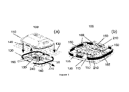
[0040] The present disclosure provides a subsea assembly 100 for imaging and
analysing a submerged net 130, e.g. that of a fish pen. The subsea assembly
100
according to the present disclosure comprises a first subsea unit 110 for
being
positioned on a first side of the net 130 and a second subsea unit 120 for
being
CA 03228647 2024- 2-9
WO 2023/018336 PCT/N02022/050192
6
positioned on a second side of the net 130, opposite to the first subsea unit
110.
The first subsea unit 110 and second subsea unit 120 are, as schematically
illustrated in figures la and lb, each provided with at least two parallelly
oriented
belt assemblies 150. The first subsea unit 110 and second subsea unit 120 may
according to any embodiment of the invention each be provided with two
parallelly oriented belt assemblies 150. The various embodiments of the
present
disclosure will be described and illustrated for an example where the first
subsea
unit 110 and second subsea unit 120 are each provided with two parallelly
oriented belt assemblies 150. A person skilled in the art with knowledge of
the
present disclosure will appreciate, however, that each embodiment of the
present
disclosure may be generalized such that at least one of the first subsea unit
110
and the second subsea unit 120 is/are provided with more than two parallelly
oriented belt assemblies 150.
[0041] A belt assembly 150 may in the context of the present disclosure be
understood
by a person skilled in the art as the collection of wheels, track 160,
bearings,
supports, etc. necessary to enable continuous track propulsion of the subsea
units, and hence the subsea assembly 100. Each belt assembly 150 may as
schematically illustrated in figures la and lb for example comprise a rear
road
wheel 170, optionally one or more middle road wheels 180, a front road wheel
190 and a track 160. Additional elements such as bearings, fastening
mechanisms etc., may be provided in a variety of ways as will be appreciated
by
a person skilled in the art with knowledge of the present disclosure. The
terms
"front", "middle" and "rear" may here be defined relative to the driving
direction
220 of the subsea assembly 100. However, as the driving direction 220 may be
reversed, said terms are largely used herein to refer to the relative position
of
the road wheels 170,180,190, meaning in practice that any middle road wheel
180 is placed between the front road wheel 190 and the rear road wheel 170. A
belt assembly 150, or more generally a subsea unit 110,120, may further be
considered as comprising a driving unit 380 for enabling the belt assembly to
provide continuous track propulsion for the subsea unit 110,120 to which it
belongs. A driving unit 380 may for example comprise a battery, and a
conventional motor, or alternatively a motor in the hub of any one or more
wheel
of the belt assembly 150. Figure 11 schematically illustrates a subsea unit
110,120, illustrated with a transparent base, where the subsea unit 110,120
comprises a driving unit 380 and an on-board computer 382.
CA 03228647 2024- 2-9
WO 2023/018336 PCT/N02022/050192
7
[0042] Each belt assembly 150 of the subsea units 110,120 may, as illustrated
in figures
la and lb, be arranged such that the ground pad 165 of the track 160 of each
belt assembly 150 protrudes a non-zero distance from the underside of the
relevant subsea unit 110,120. The ground pad 165 of each belt assembly 150 of
the first subsea unit 110 may thus in other words be said to protrude a
nonzero
distance from the underside of the first subsea unit 110, while the ground pad
165 of each belt assembly 150 of the second subsea unit 120 may be said to
protrude a nonzero distance from the underside of the second subsea unit 120.
A
person skilled in the art with knowledge of the present disclosure will
appreciate
that the ground pad 165 of any belt assembly 150 may be interpreted as the
part
of a track 160 that lies between any two road wheels. A ground pad 165 may
thus be considered as a part of a track 160. The ground pad 165 of any track
160
may according to the present disclosure be considered as planar, or at least
essentially planar, where "essentially planar" may be interpreted as meaning
for
example that the ground pad 165 of any belt assembly 150 may be tilted by <10
degrees, or be at least in part wavy, e.g. due to the track 160 not being
completely tight.
[0043] The first subsea unit 110 and second subsea unit 120 may, as
schematically
illustrated in figures la and lb, be arranged on opposite sides of the net
130.
The first subsea unit 110 and second subsea unit 120 may be aligned relative
to
one another such that the at least two belt assemblies 150 of the first
cleaning
110 unit are aligned with and adjoin separate belt assemblies 150 of the
second
subsea unit 120. The ground pad 165 of each respective track 160 of each belt
assembly 150 of the first subsea unit 110 may, as schematically illustrated in
figure lb, be positioned such that each said ground pad 165 adjoins the ground
pad 165 of the track 130 of separate belt assemblies 150 of the second subsea
unit 120. Note that in figure lb, one of the subsea units 110,120 of the
subsea
assembly 100 is schematically illustrated as partly transparent for
illustrative
purposes. A person skilled in the art with knowledge of the present disclosure
will
appreciate that a net 130 may be present between any two ground pads 165
described as adjoining in the above context. Figures la and lb illustrate an
example where the first subsea unit 110 and second subsea unit 120 are
positioned on opposite sides of a net 130 such that the ground pad 165 of the
track 160 of each belt assembly 150 of the first cleaning 110 unit adjoins,
via the
net 130, a ground pad 165 of the track 160 of a belt assembly 150 of the
second
subsea unit 120.
CA 03228647 2024- 2-9
WO 2023/018336 PCT/N02022/050192
8
[0044] The track 160 of each belt assembly 150 is, as schematically
illustrated in figure
lb, provided with magnets 210. The magnets 210 are provided in order to
generate an attractive force between the belt assemblies 150 of the first
subsea
unit 110 and the belt assemblies 150 of the second subsea unit 120 such that
the
subsea assembly 100 may adhere to a net 130. A track 160 of a belt assembly
150 of the first subsea unit 110 may as a way of example comprise magnets 210
with a first polarity, while a track 160 of a belt assembly 150 of the second
subsea unit 120 may comprise magnets 210 with a second polarity, opposite to
the first polarity. When the tracks 160 of said at least two belt assemblies
150
are positioned such that they adjoin, an attractive force will occur between
them
such that a frictional force will be obtained between each subsea unit 110,120
and the net 130. The subsea assembly 100 may thus due to this attractive
force,
and the resulting frictional force, adhere to the net 130 such that the two
subsea
units 110,120 may maintain a position on the net 130 relative to one another.
A
person skilled in the art with knowledge of the present disclosure will
appreciate
that there are numerous degrees of freedom in the configuration of the magnets
210 in each track 160. The magnets 210 in two, first and second, adjoining
tracks 160 may, as a way of example, be such that all the magnets 210 of the
first track 160 have the same polarity, while all the magnets 210 in the
second
track 160, adjoining the first track 160, have the opposite polarity of those
in the
first track 160. Another example is that the magnets 210 in two adjoining
tracks
160 may be such that any two adjacent magnets 210 in any one track 160 have
opposite polarities, but where the tracks 160 of the two subsea units are
adjoining each other with a relative shift such that magnets 210 of opposite
polarities are adjoining/attracting one another. The latter configuration may
be
utilized in order to counteract skidding of the tracks 160.
[0045] The subsea assembly may according to the present disclosure move across
a net
by means of the belt assemblies of the first subsea unit and the second subsea
unit. The adhesion to the net obtained by the magnetic attraction between
adjoining tracks of the two subsea units will result in a grip for the subsea
assembly such that movement is enabled. Said grip may thus be termed a
magnetically induced grip. A person skilled in the art with knowledge of the
present disclosure will appreciate that each belt assembly of the subsea
assembly
may operate as a continuous track vehicle propulsion system that is configured
to
operate under water, i.e. where each belt assembly is provided with one or
more
of a motor, gear system, water tight gaskets, power supply, etc. The subsea
CA 03228647 2024- 2-9
WO 2023/018336 PCT/N02022/050192
9
units may generally be provided with other parts necessary for allowing the
subsea assembly to move across a net. A person skilled in the art with
knowledge
of the present disclosure will appreciate that such parts may comprise e.g.
watertight housing, transmitter, receiver, lighting device, battery, etc. At
least
one of the first subsea unit and the second subsea unit may as a way of
example
comprise a driving unit, where the driving unit comprises at least one
electric
motor and a battery. The electric motor may here be connected to one or more
of the wheels of a belt assembly of the first subsea unit and/or the second
subsea unit via for example a shaft or another suitable power transfer
mechanism. In another example the first subsea unit and the second subsea unit
may each comprise a driving unit as described above. A person skilled in the
art
with knowledge of the present disclosure will appreciate that there are
several
options for how to drive the belt assemblies of the subsea units.
[0046] The subsea assembly 100 may, as illustrated in figures la and lb be
provided
with cleaning means 140 for cleaning a submerged net 130. Both or either of
the
first subsea unit 110 and the second subsea unit 120 may be provided with
cleaning means 140. Cleaning means 140 may according to the present
disclosure be any suitable means for cleaning a net 130. As a way of example,
the subsea assembly 100 may be provided with one or more brushes, e.g. a
rotating brush. The one or more brushes may be provided on only one of the
subsea units 110,120 or alternatively be distributed between the two subsea
units 110,120. A brush may brush against the net in order to clean the net of
unwanted substances such a biofouling. In another example the cleaning means
140 may comprise a water-based cleaning means 140, such as a pressure
cleaner. In yet another example the cleaning means 140 may comprise one or
more friction surfaces, such as a scrub or stationary brush, suitable for
cleaning a
net by being moved across the net 130.
[0047] The first subsea unit 110 is according to the present disclosure
provided with a
line camera 230. The latter is schematically illustrated in figures 2 and 5a.
The
line camera 230 may be considered as arranged on the side of the first subsea
unit 110 that faces the net 130 under operation of the subsea assembly 100.
The
line camera 230 may as a way of example span between two parallelly oriented
belt assemblies 150 of the first subsea unit 110, and optionally be arranged
perpendicularly to two parallelly oriented belt assemblies 150 of the first
subsea
unit 110. A line camera 230 may generally be arranged perpendicularly to the
driving direction of the subsea assembly 100, which may be beneficial in order
to
CA 03228647 2024- 2-9
WO 2023/018336 PCT/N02022/050192
optimize how much of the net that is captured per pass of the subsea assembly
100. As a way of example, a line camera 230 may be configured to span the full
width of the first subsea unit 110. The latter may be obtained by placing the
line
camera in front of, or behind, the parallelly oriented belt assemblies 150 of
the
first subsea unit 110. Figure 9a schematically illustrates a first subsea unit
provided with a line camera 230, where the line camera is configured to span
the
full width of the first subsea unit 110.
[0048] The line camera may according to the disclosure be used to capture
image data
in the form of line images of the net as the subsea assembly adheres to and
moves across the net. The image data may be captured continuously, and the
capture rate may for example be set according to a desired resolution and the
speed in which the subsea assembly moves across the net. The image data
captured by the line camera may further be communicated to an onboard
computer of the subsea assembly that is configured to generate a two-
dimensional image of a portion of the submerged net based on the received
image data. The portion of the net imaged in the two-dimensional image may
generally be any portion of the net, for example 0.5 square meter or the whole
net. By providing the subsea assembly with a line camera it is possible to
obtain
a short distance between the line camera and the net, a distance that due to
the
magnetic adhesion of the subsea assembly to the net will be fixed over time.
Using a line camera in combination with the subsea assembly according to this
disclosure has been found to result in images with a high contrast and
resolution.
Figure 8 shows an example of a two-dimensional image of a fish pen obtained
using a line camera configured to capture images with a resolution of 300 DPI.
The two-dimensional image may generally contain information about the net,
such as information on biofouling and information regarding the state of the
net,
i.e. signs of wear, holes, etc. The two-dimensional image may for example be
communicated to an operator or onshore computer, or alternatively be processed
on bord the subsea assembly, for example by an onboard computer.
[0049] According to the present disclosure, the two-dimensional image may be
used in
order to determine the strand thickness of at least one strand of the
submerged
net. As can be seen from figure 8, the two-dimensional image will have a
resolution where each pixel may be converted to a spatial distance. It will be
appreciated by a person skilled in the art with knowledge of the present
disclosure that said conversion, also known as a calibration, will be
dependent on
parameters such as the distance between the net and the line camera, the type
CA 03228647 2024- 2-9
WO 2023/018336 PCT/N02022/050192
11
of line camera used, the capture rate of the line camera and the speed in
which
the subsea assembly moves across the net. Said calibration may for example be
performed by capturing a reference image of a known object with a known size,
e.g. a strand of the net having a known thickness, and subsequently assigning
a
spatial distance represented by each pixel of the image. Once said conversion
has been performed, the two-dimensional image may then be analysed, either
manually or digitally to obtain information regarding the strand thickness of
one
or more strands of the net. It will be appreciated by a person skilled in the
art
with knowledge of the present invention that once the two-dimensional image
has been obtained according to this disclosure, the two-dimensional image may
be digitally analysed using a wide range of existing analytic tools, e.g.
commercially available software tools, in order to determine the strand
thickness
of one or more strands of the net. Said digital analysis may according to any
embodiment of the invention be performed by an on-board computer of the
subsea assembly.
[0050] According to the present disclosure, at least parts of the above method
may be
executed for example by an on-board computer of the subsea device or a
separate multi-purpose computer. Said method may be summarized as
comprising initially receiving by said computer, image data from a line camera
of
a subsea assembly as the subsea assembly adheres to and moves across the
submerged net. The computer may then, subsequently generate a two-
dimensional image of a portion of the submerged net based on the received
image data, before determining the strand thickness of the at least one strand
of
the submerged net based on the two-dimensional image. Parts of the method
described herein may generally be considered as a computer-implemented
method, particularly the steps of the method that may be performed by a
computer, e.g., an on-board computer of the subsea device.
[0051] As stated above, the exact process of determining the strand thickness
of the at
least one strand of the submerged net based on the two-dimensional image may
vary and said process may be implemented in a variety of ways. However, there
are certain process steps that may be implemented in the method in order to
for
example filter or modify the two-dimensional image in order to ease later
analysis. In an embodiment of the disclosure, determining the strand thickness
of
the strand of the submerged net may comprise a step of converting the two-
dimensional image into a first binary image. An example of a first binary
image is
show in figure 10a. Converting the two-dimensional image into a first binary
CA 03228647 2024- 2-9
WO 2023/018336 PCT/N02022/050192
12
image has the benefit that that the net may be made to appear more distinctly
outlined than in the two-dimensional image. Each pixel of the first binary
image
may in the process of converting the two-dimensional image into a first binary
image be made to represent a corresponding pixel in the two-dimensional image.
Each pixel of the first binary image may then be assigned a first binary value
if
the brightness of the corresponding pixel in the two-dimensional image is
above/below a first predetermined threshold. Likewise, each pixel of the first
binary image may assigned a second binary value if the brightness of the
corresponding pixel in the two-dimensional image is below/above a first
predetermined threshold. Each pixel of the first binary image may in a first
example be assigned a first binary value if the brightness of the
corresponding
pixel in the two-dimensional image is above a first predetermined threshold if
the
strands of the net appear bright in the two-dimensional image. The latter may
occur if the images taken by the line camera are taken using a front light,
i.e.
using a light source in front of the net relative to the line camera. In the
first
example each pixel of the first binary image may assigned a second binary
value
if the brightness of the corresponding pixel in the two-dimensional image is
below a first predetermined threshold. Each pixel of the first binary image
may in
a second example be assigned a first binary value if the brightness of the
corresponding pixel in the two-dimensional image is below a first
predetermined
threshold if the strands of the net appear as dark in the two-dimensional
image.
The latter may occur if the images taken by the line camera are taken using a
backlight, i.e. using a light source behind the net relative to the line
camera. In
the second example each pixel of the first binary image may assigned a second
binary value if the brightness of the corresponding pixel in the two-
dimensional
image is above a first predetermined threshold. The first predetermined
threshold
may be chosen for example based on the contrast level in the two-dimensional
image.
[0052] In order to further make it easier to determine the strand thickness of
the at
least one strand of the submerged net based on the two-dimensional image, one
may filter out the strand knots from the first binary image. The latter may be
beneficial as the knots do not represent a true thickness of any strand of the
submerged net. Said filtering of knots may be performed by initially
converting
the first binary image into a distance map image as shown in figure 10b. Each
pixel of the distance map image may be made to represent a corresponding pixel
in the first binary image, and each pixel of the distance map image may be
CA 03228647 2024- 2-9
WO 2023/018336 PCT/N02022/050192
13
assigned a value that denotes the distance between the corresponding pixel in
the first binary image and the most proximate pixel to that corresponding
pixel in
the first binary image having the second binary value. Any pixel in the
distance
map image corresponding to a pixel in the first binary image having the second
binary value, may be assigned a zero value in the distance map image. The
resulting distance map image will consequently be a map that illustrates the
density of the net in the two-dimensional image, where the knots will appear
with
a high value relative to a single strand. The knots may consequently be
filtered
out of the distance map image by assigning a zero value to each pixel of the
distance map image having a value above a second predetermined threshold
value. Said second predetermined threshold value may for example be chosen
based on a known size of said knots, which for example may be manually
measured. The distance map image may subsequently be converted into a
second binary image, where each pixel of the second binary image represents a
corresponding pixel in the distance map image. Each pixel of the second binary
image may then be assigned the first binary value if the brightness of the
corresponding pixel in the distance map image is non-zero and be assigned the
second binary value if the brightness of the corresponding pixel in the
distance
map image is zero. The resulting second binary image may thus take the form as
shown in figure 10c, i.e. be a black and white image showing only free-
standing
strands of the submerged net. The second binary image may then be used to
determine the strand thickness of the at least one strand of the submerged net
based on the second binary image. It will be appreciated that the above
process
may be used to filter out visible intact knots in the first binary image. A
hole in
the net, for example due to a loosened or missing knot, will appear in the two-
dimensional image, the first binary image, the distance map image and the
second binary image.
[0053] As previously indicated, the strand thickness of the at least one
strand of the
submerged net may be found based on the second binary image in a variety of
ways. In a particular example the strand thickness of the at least one strand
of
the submerged net may be found by initially defining a virtual rectangle
around
each of the free-standing strands of the submerged net, where the sides of
each
rectangle are adjoining the outer contour of one of the free-standing strands.
By
subsequently using the corner coordinates of each rectangle, lines may then be
drawn that cross each free-standing strand. Each of the said lines may then be
used to find the thickness of each free-standing strand, for example by
counting
CA 03228647 2024- 2-9
WO 2023/018336 PCT/N02022/050192
14
the number of pixels of each line that overlap a pixel having the first binary
value. Figure 10d shows an image where the resulting strand thicknesses of
some strands of the net are shown.
[0054] The above method may according to the present disclosure further
comprise a
step of generating a data file containing information on the thickness of the
at
least one strand of the submerged net and the position of the at least one
strand
in the two-dimensional image. Performing such a step at an onboard computer of
the subsea assembly has an advantage as said data file will be smaller in
size,
i.e. kB, MB, GB, ..., than the two dimensional image, hence reducing the need
for
bandwidth between the subsea assembly and any onshore server, controller or
similar, with which the subsea assembly may communicate. The presence of an
onboard computer of the subsea assembly generally has the advantage that the
subsea assembly may in itself perform pre-processing of the two-dimensional
image and send the results of this pre-processing to any onshore server,
controller or similar rather than to send the full two-dimensional image. The
requirements for bandwidth between the subsea assembly and server, controller
or similar is then reduced. The data
[0055] The first subsea unit 110 may as schematically illustrated in figure 2
be provided
with a line camera 230, while the second subsea 120 unit may, as schematically
illustrated in figure la be provided with a background element 240. The line
camera 230 and the background element 240 may be arranged such that they
face each other when the subsea assembly 100 adhere to the net 130. The line
camera 230 and background element 240 may thus respectively be considered as
arranged on the side of the first subsea unit 110 and second subsea unit 120
that
face the net 130 under operation of the subsea assembly 100. The line camera
230 and background element 240 may as a way of example be positioned
between two parallelly oriented belt assemblies 150 of the first subsea unit
110
and second subsea unit 120 respectively. The line camera 230 may more
specifically be positioned between two parallelly oriented belt assemblies 150
of
the first subsea unit 110, while the background element 240 may cover at least
a
part of the area between the two parallelly oriented belt assemblies 150 of
the
second subsea unit 120. In a particular embodiment of the disclosure the first
subsea unit 110 may be provided with a line camera 230 and a background
element 240, while the second subsea 120 unit may be provided with a line
camera 230 and a background element 240.
CA 03228647 2024- 2-9
WO 2023/018336 PCT/N02022/050192
[0056] A background element may generally in the context of the present
invention be
considered as an element shaped to provide a fixed homogeneous background
for the line camera when the latter captures an image. Generally, the
background
element may be shaped according to the type of camera used such that an image
of the background element results in an image with no or at least limited
contrast.
[0057] The use of a background element in the second subsea unit has been
found to be
beneficial as the background element provides a fixed background for the line
camera of the first subsea unit. The net to be imaged by the line camera will
during operation of the subsea assembly be present between the line camera and
the background element, thus enabling the line camera to image the net using
the background element as a fixed background. Multiple images of the net may
thus be compared without having to consider various lighting conditions that
for
example may occur if one where to image a net using the open sea as a
background. The open sea will for example give a lighting effect in a captured
image dependent on the depth of the subsea assembly during the capture of the
image. The fixed background provided by the background element has further
been found to enable high resolution images to be captured by the line camera.
The latter is useful for detecting holes in the net, wear of the net, and
particularly
early signs of wear of the net. Early signs of wear allow for example
maintenance
to be conducted prior to a hole developing in the net, thereby hindering for
example the fish escaping the fish pen. Figure 8 shows an example of an image
of a fish pen obtained using a line camera configured to capture images with a
resolution of 300 DPI and using a plane surface as a background element.
[0058] The background element 240 may as schematically illustrated in figure
la
comprise a plane surface, which may as a way of example be oriented in
parallel
with the ground pad 165 of the tracks 160 of the belt assemblies 150 of the
second subsea unit 120. A plane background element 240 may generally be
arranged such that it is parallel with the net 130 during operation of the
subsea
assembly. It will be appreciated by a person skilled in the art with knowledge
of
the present disclosure that the background element 240 in this embodiment
doesn't have to be perfectly in parallel with the net 130 during operation of
the
subsea assembly 100. A plane background element 240 may generally be
arranged such that it is within 10 degrees or 5 degrees of being in parallel
with
the net 130 during operation of the subsea assembly. A background element 240
CA 03228647 2024- 2-9
WO 2023/018336 PCT/N02022/050192
16
comprising a plane surface may as a way of example be a plate, for example a
metal plate, a plastic plate, polymer plate or a composite plate.
[0059] The first subsea unit 110 and/or the second subsea unit 120 may as
schematically illustrated in figure 3 further comprises one or more light
sources
250. The presence of a light source 250 in at least one of the first subsea
unit
110 and the second subsea unit 120 has/have been found to be beneficial in
order to illuminate the net 130 to be imaged by the line camera 250. As the
first
subsea unit 110 and the second subsea unit 120 are facing each other during
operation of the subsea assembly 100, with limited light from the ambient, a
light
source 250 may be present for example next to the line camera 230 on the first
subsea unit 110 in order to illuminate the net 130 to be imaged. A light
source
250 may additionally or alternatively be provided on the second subsea unit
120,
for example facing the line camera 230 of the first subsea unit 110 when the
subsea assembly 100 adhere to the net 130.
[0060] The light source may in any embodiment of the present disclosure be a
light
source configured to radiate white light. Other colours may alternatively be
used,
for example in order to enhance contrast between the net to be imaged and any
biofouling, or other substances of interest that may be present on the net.
The
light source may in any embodiment of the present disclosure comprise at least
one LED.
[0061] The light source 250 may as schematically illustrated in figure 4 be
integrated in
the background element 240. Integration in the background element 240 enables
for example bright field images to be captured by the line camera 230,
allowing
for a high contrast of the net. The background element 240 may as a way of
example comprise an array of light sources 250 such as LEDs 270. The
background element 240 may in a particular embodiment be configured to
generate Kohler illumination, i.e. even illumination, ensuring that the light
source
250 does not appear in images captured by the line camera 230. Kohler
illumination may for example be achieved at least in part by providing a
diffuse
transmitter in front of an array of light sources 250 such as LEDs 270. It
will be
appreciated by a person skilled in the art with knowledge of the present
disclosure that perfect Kohler illumination may generally be difficult to
obtain.
Kohler illumination may thus in the context of the present disclosure be
considered as illumination illuminating the field of view of the line camera
with a
relative intensity variation of maximum 15 % or alternatively maximum 5 %
CA 03228647 2024- 2-9
WO 2023/018336 PCT/N02022/050192
17
[0062] Figure 5b schematically illustrates an embodiment of the present
disclosure
where the light source 250 has an elongated shape, or where the light source
250 comprises a plurality of LEDs 270 arranged in a line. Either configuration
may optionally be arranged perpendicularly to the driving direction of the
subsea
assembly 100. The elongate shape may in other words be elongate in the
direction perpendicularly to the driving direction of the subsea assembly 100,
or
the line of LEDs may be arranged in the direction perpendicularly to the
driving
direction of the subsea assembly 100. An elongate light source 250 and/or a
light
source 250 comprising a plurality of LEDs 270 arranged in a line has been
found
to be beneficial in order to save power in the subsea assembly 100. Such a
light
source 250 may be used to selectively illuminate a section of the net 130,
hence
allowing for sampling of a linear segment of the net 130 per time. An elongate
light source 250 and/or a light source 250 comprising a plurality of LEDs 270
arranged in a line may for example be combined with the use of a line camera
230 where the elongate light source 250 and/or the light source 250 comprising
a plurality of LEDs 270 arranged in a line may be aligned with the line camera
230, e.g. such that any part of the elongate light source 250 and/or the light
source 250 comprising a plurality of LEDs 270 arranged in a line is arranged
facing into the line camera 230 when the subsea assembly 100 is being
operated.
The use of an elongate light source 250 and/or a light source 250 comprising a
plurality of LEDs 270 arranged in a line may in the latter case optimize power
consumption, as a limited amount of light will be wasted for illuminating
parts of
the net 130 not being imaged by the line camera 230. An elongate light source
250 and/or a light source 250 comprising a plurality of LEDs 270 arranged in a
line may as schematically illustrated in figure 5 and 9 be integrated in the
background element 240.
[0063] The light source may according to any embodiment of the present
disclosure be
configured to flash or alternatively be configured to pulsate. A light source
configured to flash or configured to pulsate may be used to reduce the power
consumption of the subsea assembly, as the light source may be synchronized
with the capture rate of the line camera. A camera having a capture rate of 1
fps
may thus only need illumination once per second, allowing the light source to
be
off or idle for the rest of the time. A person skilled in the art with
knowledge of
the present disclosure will appreciate how to obtain a light source that is
configured to flash or at least be configured to pulsate. The light source, or
a
CA 03228647 2024- 2-9
WO 2023/018336 PCT/N02022/050192
18
control unit for the light source may for example be provided with necessary
capacitors sufficiently sized in order to power the light source.
[0064] Figure 6 schematically illustrates an embodiment of the present
disclosure where
the second subsea unit 120 further comprises a filter 280 arranged in front of
the
line camera 230. A filter 280 may for example be used in order to filter out
the
colour of any biofouling on the net 130 in order to enhance contrast with the
net
130. A filter 280 may alternatively be used in order to filter out the colour
of the
surrounding water. As a way of example, the filter 280 may be a band-stop
filter
or a band pass filter.
[0065] Instead of, or in additional to using a filter, the line camera may
comprise a
spectrometer. A spectrometer may here be used in order to obtain images of the
net based on selected wavelengths of interest. The effects of using a
spectrometer may be considered similar to using a filter but has the
additional
advantage that more information may be obtained by any one image relative to
what may be obtained using for example a normal image sensor like a charge-
coupled device in combination with a filter.
[0066] When used to clean the net of a fish pen, the first subsea unit may in
a particular
embodiment of the present disclosure be positioned on the side of the net
facing
into the fish pen, while the second subsea unit may be positioned on the side
of
the net facing out from the fish pen. As obstacles such as ropes and rope
knots
are typically positioned on the outer surface of the fish pen, it is
beneficial to
image the net of the fish pen from the inside of the fish pen. The line camera
may thus in this embodiment be positioned on the side of the net facing into
the
fish pen, thus allowing for a shorter and more permanent distance between the
line camera and the net relative to what would have been possible if the line
camera was provided on the subsea unit positioned on the side of the net
facing
out from the fish pen.
[0067] The subsea assembly may according to the present disclosure be
dimensioned
according to the net. A typical extension of the subsea assembly is between 80
cm and 200 cm. The extension of the subsea assembly is according to a specific
embodiment of the present disclosure less than 150 cm.
[0068] Each road wheel 170,180,190 of the subsea assembly may, as
schematically
illustrated in figure 7, be provided with a suspension 200. The suspension 200
for
each road wheel 170,180,190 may be configured for shifting the position of
said
road wheel 170,180,190 in a direction at least in part perpendicular to a
driving
direction 220 of the subsea assembly. An example of such a distance is less
than
CA 03228647 2024- 2-9
WO 2023/018336 PCT/N02022/050192
19
centimetres, or more specifically a distance of between 3 and 5 centimetres.
The suspension 200 of the road wheels 170,180,190 aims inter alia to enable
the
subsea assembly to traverse obstacles of the net, such as ropes, knots or
similar.
The combination of the road wheel suspension 200 and the presence of three
road wheels 170,180,190 means that any two adjoining tracks 160 may retain
magnetic attraction even when the subsea assembly is traversing an obstacle.
As
a way of example one can assume a subsea assembly according to the present
disclosure traversing a rope of the net. As the subsea assembly drives across
the
rope, the front road wheels 190 of each pair of adjoining tracks 160 will be
displaced away from one another and the magnetic attraction between the part
of the ground pad 165 between the front road wheel 190 and middle road wheel
180 of the pair of adjoining tracks 160 will be strongly reduced. A subsea
assembly having only two road wheels would in such an instance likely lose its
magnet-induced grip on the net and consequently fall of the net. The subsea
assembly according to the present disclosure would on the contrary maintain
its
magnet induced grip on the net, as the part of the ground pad 165 between the
middle road wheel 180 and read road wheel 170 would still be adjoining, such
that sufficient magnetic attraction may be maintained. Following the same
example, the subsea assembly will upon continuing its traversing of said rope
move relative to the rope such that the front road wheels 190 once again are
brought in contact with each other, but where the middle road wheels 180
subsequently are displaced from their default position using their respective
suspension 200. At such a position the subsea assembly according to the
present
disclosure may maintain its adhesion to the net due to the magnet attraction
between the ground pad 165 around the front road wheels 190 and the rear road
wheels 170. The subsea assembly will upon continuing its traversing of said
rope,
move relative to the rope such that the middle road wheels 180 once again are
brought in contact with each other, but where the rear road wheels 170
subsequently are displaced from their default position using their respective
suspension 200. The latter situation is equivalent to the situation where the
front
road wheels 190 were displaced.
[0069] Figure lb and 7 schematically illustrate an embodiment of the present
disclosure
where each belt assembly 150 further comprises a damper wheel 225. Said
damper wheel 225 may typically be positioned at a non-zero distance from the
ground pad 165 of the belt assembly 150 to which it belongs. The latter
location
may here be in a direction perpendicular to the driving direction 220 of said
belt
CA 03228647 2024- 2-9
WO 2023/018336 PCT/N02022/050192
assembly 150. A damper wheel 225 may be utilized in order to compensate for
any strain in a track 160 caused when the subsea assembly traverses an
obstacle
that causes one of its road wheels 170,180,190 to be displaced from their non-
damped position. A road wheel 170,180,190 being displaced as a consequence of
the subsea assembly traversing an obstacle will result in the relevant track
160
having to conform to the shape of the object that is being traversed. Instead
of
the track 160 becoming strained due to the displacement of a road wheel
170,180,190, the damper wheel 225 may instead compensate for the shift in
position of the road wheel 170,180,190, i.e. compensate for the resulting
strain
in the track 160 by being itself displaced. Each damper wheel 225 may thus in
other words be provided with a suspension 200 for shifting the position of
said
damper wheel 225 in order to compensate for a shift in position of a road
wheel
170,180,190. As a way of example, if a road wheel 170,180,190 of a belt
assembly 150 is displaced in a direction perpendicular to the driving
direction 220
of said belt assembly 150, a damper wheel 225 of that belt assembly may be
displaced in the opposite direction of the displaced road wheel 170,180,190 in
order to compensate for the increased length requirement on the track 160 due
to the belt having to conform to the shape of the object that is being
traversed. A
typical object that needs to be traversed may as previously mentioned be a
rope
or a knot, which for example could have a diameter or extension of 3-5
centimetres. Each road wheel 170,180,190 may thus be provided with a
suspension 200 for shifting the position of said road wheel 170,180,190 a
distance of at least 3-5 centimetres in a direction at least in part
perpendicular to
a driving direction 220 of the subsea assembly. Each damper wheel 225 may
consequently be provided with a suspension 200 for shifting the position of
said
damper wheel 225 a distance of 3-5 centimetres. In general, any road wheel
170,180,190 may be provided with a suspension 200 for shifting the position of
said road wheel 170,180,190 a distance of up to 10 centimetres in a direction
at
least in part perpendicular to a driving direction 220 of the subsea assembly.
A
suspension 200 may generally be any suitable suspension 200. Examples of
suitable suspensions 200 are spring-based suspension and hydraulic suspension.
[0070] The subsea assembly may according to any embodiment of the present
disclosure be configured to traverse obstacles of a given size. As a way of
example, the subsea assembly may be configured to traverse an obstacle such as
a rope or a rope knot. In order for the subsea assembly to not loose adhesion
to
the net upon traversing an obstacle, the road wheels of each belt assembly may
CA 03228647 2024- 2-9
WO 2023/018336 PCT/N02022/050192
21
be spaced apart depending on the dimension of the obstacle to be traversed. In
one embodiment of the present disclosure the road wheels of each individual
belt
assembly may be separated by a distance of at least 3-5 centimetres. The
latter
distance is here measured between the surface of two adjacent road wheels. The
road wheels of each individual belt assembly may generally be separated by a
distance longer than 5 centimetres. It will be appreciated by a person skilled
in
the art that the upper limit for the spacing between two adjacent road wheels
of
the same belt assembly is determined by for example the obstacle that it is
desirable to traverse, and/or for example the dimension and weight of the
subsea
assembly. A distance between two adjacent road wheels of at least 3-5
centimetres, alternatively 5 - 10 centimetres, is considered adequate for most
fish pen. Such a distance will allow the subsea assembly to traverse ropes and
rope knots without having two adjacent road wheels of the same belt assembly
being displaced by the rope.
[0071] Any belt assembly 150 may, as illustrated in figure lb and 7, further
comprise
any number of drive wheels 320, damping wheels 225, road wheels, idlers
and/or tightener wheels 340. As a way of example, any belt assembly may be
provided by a driving wheel 320, i.e. a wheel that supplies driving power to
the
track 160. Any road wheel or damper wheel 225 may in any relevant
embodiments of the present disclosure be a driving wheel 320. A person skilled
in
the art would appreciate that the subsea assembly according to the present
disclosure may comprise any number of additional wheels, e.g. dependent on the
exact size and shape of the belt assemblies 150. A tightener wheel 340 may for
example be provided to form the previously described driving edge 245 or
trailing
edge 255. In a particular embodiment of the present disclosure, each belt
assembly 150 may further comprise an additional middle road wheel 180. An
additional middle road wheel 180 may contribute to increase the attraction
between two adjoining belt assemblies 150 when the subsea assembly traverses
an obstacle. An additional middle road wheel 180 may contribute to ensuring a
plane surface of the ground pad 165 of two adjoining tracks 160 being in
contact
during the traversing of said obstacle. The size of each wheel of the subsea
assembly will generally depend on the size of each subsea unit. The size of
each
wheel may typically be dimensioned according to the type of track used, for
example such that the track may run across the wheels without experiencing too
great a curvature. In a particular embodiment of the present disclosure each
wheel of each belt assembly has a diameter in the range of 60 mm to 120 mm.
CA 03228647 2024- 2-9
WO 2023/018336 PCT/N02022/050192
22
Such a diameter has been found to be preferable when the track is made from
silicone, rubber or plastic. Any wheel of a belt assembly that is positioned
farthest to the front or back along the driving direction of a belt assembly
will
typically inflict the largest curvature on the track. These farthermost wheels
may
thus have a diameter that is larger than that of any road wheels appurtenant
to
the same belt assembly, e.g. in the range from 10% - 250% larger, in
particularly in the range from 50% - 100 % larger. Any one or both of the
farthermost wheels may for example be a driving wheel 320.
[0072] The track of any belt assembly of the subsea assembly may according to
any
embodiment of the present disclosure be made at least in part from rubber,
plastic or silicone. A person skilled in the art will appreciate that the
track may be
made from other materials than those listed explicitly herein. The track may
for
example be made from a combination of materials, e.g. a combination of those
mentioned above.
[0073] It will be appreciated that the subsea assembly according to any
embodiment of
the present disclosure is not limited to cleaning a net. The subsea assembly
may
according to any embodiment of the present disclosure alternatively be used in
order to clean a seine, net cage, a water permeable sheet, water impermeable
sheet or similar. Other examples are watertight tarpaulin, perforated
tarpaulin, or
similar.
[0074] Other advantageous features will be apparent from the accompanying
claims.
CA 03228647 2024- 2-9