Note : Les descriptions sont présentées dans la langue officielle dans laquelle elles ont été soumises.
CA 03229594 2024-02-16
WO 2023/048623 PCT/SE2022/050833
1
CONTRAST AGENT MIXER
TECHNICAL FIELD
The present invention relates to mixer and more precisely to a contrast agent
mixer suitable for providing a per-oral negative contrast agent foam and
associated
method and system.
BACKGROUND
Computerized tomography (CT) is a diagnostic imaging technique that creates
detailed images of a body, e.g.õ a human body, with its interior by combining
series of
X-ray captions that create cross-sectional images or slices of parenchymal
organs,
muscles, fat tissue, bones, vessels, lymph nodules, etc. in health and
disease. Today CT
is a frequently used tool due to its lower cost and notably faster
examinations compared
to other tomography techniques such as magnetic resonance tomography, and also
due
to its higher availability worldwide. In addition to its common use in
diagnosing cancer,
CT is widely used to facilitate diagnosing a variety of other diseases and
disorders, such
as inflammatory diseases, trauma, anomalies, etc.
In CT of the abdomen (CT-abd), contrast agents are used for demarcating
structures by increasing differences in density between tissue compartments.
The
enhanced difference in contrast improves visualization of details necessary
for the
radiologist to detect and follow abnormalities within the abdomen and pelvis
over time
and thus, with a possible medical diagnosis. The radiodensity of structures
and/or
materials is measured in Hounsfield Units (HU). The abdominal organs and
structures
are displayed in a variety of colors in the grey scale depending on the
radiodensity of
their composition, from white (such as bones; around +1000 HU), to light grey
(such as
blood vessels; around +70 HU), and black (such as air in the lungs; around -
1000 HU).
A patient routinely referred to CT-abd is usually prepared with a per-oral
agent
for demarcating the gastro-intestinal tract. Up until now, the most commonly
used
demarcating agent has been a diluted solution of an iodine contrast medium
meant for
intra-venous application, resulting in a white bowel content, i.e., with
positive HU.
Other agents are iso-osmotic solutions that provide densities of around 10 HU,
CA 03229594 2024-02-16
WO 2023/048623
PCT/SE2022/050833
2
exhibiting bowel lumen in grey, close to the color of other body structures.
Thus,
positive oral filling agents provide no or unsatisfactory contrast between the
bowel wall
and the lumen of the small intestine on CT images. As a consequence, images of
the
bowel wall are less easy to read which may result in radiological diagnoses of
reduced
quality, including both false positive and negative diagnoses. Consequently, a
negative,
"black" filling, contrast agent, with notably larger contrast against the
mucosal lining
and of the gut wall, was introduced in EP 3589331 thereby creating an
opportunity for
improved medical evaluation.
The contrast agent introduced in EP 3589331 is a fluid, aqueous foam of
microbubbles. The foam is created from a dispersion obtained by stirring,
manually or
by magnetic stirrer, a contrast powder with a liquid until a completely
homogenous
dispersion was obtained. This dispersion was mixed into a foam by manually
using a
blender. A blade of the blender is continuously kept in the dispersion without
creating
any air pocket to avoid the incorporation of extra air and the formation of
new big
bubbles. The foam is whipped until the foam is homogenous and with no visible
bubbles. In case visible bubbles are detected by bear eye at the surface of
the foam, the
bubbles are removed with a spoon or with a suction device such as a Pasteur
pipette. If
too many bubbles that may not be removed are present at the surface and/or in
the bulk,
the foam will have to be discarded or re-whipped increasing the preparation
time and
the cost of the product.
The process of producing a contrast agent foam is sensitive. Excess air will
cause an increase in overrun and consequently produce a thicker foam, as well
as the
formation of big bubbles giving a non-homogenous and high polydispersity foam.
Such
a foam would negatively interfere with the quality of the x-ray images. The
foam should
not comprise any clearly visible bubbles among the microbubbles that the foam
is made
up of.
Thus, from the above it is understood that there is room for improvements.
SUMMARY
An object of the present invention is to provide a new type of mixer which is
improved over prior art and which addresses or at least mitigates the
drawbacks
CA 03229594 2024-02-16
WO 2023/048623 PCT/SE2022/050833
3
discussed above. More specifically, an object of the invention is to provide a
contrast
agent mixer suitable for providing a per-oral negative contrast agent foam for
e.g.,
abdominal computer tomography. These objects are addressed by the technique
set forth
in the appended independent claims with preferred embodiments defined in the
dependent claims related thereto.
In a first aspect, a contrast agent mixer for providing a foam type contrast
agent
is presented. The mixer comprises a holding arrangement for supporting a
mixing
container, a substantially homogeneous circular mixer blade for mixing a
contrast
powder with a liquid in the mixing container, and a controller configured to
control a
rotational speed of the mixer blade and a vertical distance between the
holding
arrangement and the mixer blade.
In one variant, the holding arrangement is movable by a second motor
arrangement of the mixer to control the vertical distance between the holding
arrangement and the mixer blade. The second motor arrangement is controlled by
the
controller. This is beneficial as it reduces noise and vibrations during
mixing and
controlling of the distance between the mixer blade and the holding
arrangement.
In one variant, the mixer blade is arranged on a mixer shaft rotatable about a
longitudinal axis of the mixer shaft by a first motor arrangement controlled
by the
controller. This is beneficial as motor arrangements provide a controllable
torque, are
energy efficient, silent, cost effective and comparably easy to control.
In one variant, the mixer blade is movable by the second motor arrangement of
the mixer to control the vertical distance between the holding arrangement and
the
mixer blade. The second motor arrangement is controlled by the controller.
This is
beneficial as the cost of the mixer may be reduced to less stringent
requirement on the
second motor arrangement.
In one variant, the mixer blade is operatively connected to the first motor
arrangement by means of a clutch. Having a clutch is beneficial as it allows
for the
removal of the mixer blade from the mixer to simplify replacement and/or
cleaning of
the mixer blade.
In one variant, the clutch is a magnetic clutch comprising an upper member
operatively connected to the first motor arrangement and a lower member
operatively
CA 03229594 2024-02-16
WO 2023/048623 PCT/SE2022/050833
4
connected to the mixer blade. The upper member is connected to the lower
member by
means of one or more magnets. Using magnets for the clutch is beneficial as it
allows
the tool-less removal of the mixer blade, it provides an improved user
experience and it
reduces the time and effort needed when replacing and/or cleaning the mixer
blade.
In one variant, the lower member or the upper member of the clutch is
concavely formed, and the other of the lower member or the upper member of the
clutch
is matingly convexly formed. This is beneficial as it allows for easy and
correct
positioning of the mixer blade to the first motor arrangement reducing the
time and
effort needed when replacing and/or cleaning the mixer blade.
In one variant, the mixer blade is arranged on the mixer shaft such that a
blade
angle is formed between a plane of the mixer blade and a reference plane
perpendicular
to a longitudinal axis of the mixer shaft. The blade angle is in the range of
0,5 to 5 ,
preferably in the range of 2 to 4 . This is beneficial as the blade angle can
be used to
control the amount of air incorporated in the foam and thereby the volume of
the foam.
The blade angle increases the effectiveness of the mixer blade.
In one variant, the negative oral contrast agent mixer further comprises a
liquid
container arranged to dispense the liquid into the mixing container. This is
beneficial as
a used does not have to ensure that liquid is in the mixing container before
starting the
mixer.
In one variant, the negative oral contrast agent mixer further comprises a
valve
arranged in a fluid pathway between the liquid container and the mixing
container and
controllable between an open position and a closed position by the controller.
This is
beneficial as the controller may control when the liquid is added to the
mixing container
and/or the amount of liquid added to the mixing container.
In one variant, the negative oral contrast agent mixer further comprises a
powder container arranged to dispense the contrast powder into the mixing
container.
This is beneficial as a used does not have to ensure that contrast powder is
in the mixing
container before starting the mixer.
In one variant, the negative oral contrast agent mixer further comprises a
powder dispenser controllable, between an open position and a closed position
by the
controller. This is beneficial as the controller may control when the contrast
powder is
CA 03229594 2024-02-16
WO 2023/048623
PCT/SE2022/050833
added to the mixing container and/or the amount of contrast powder added to
the
mixing container.
In a second aspect, a method for providing a per-oral negative contrast agent
foam for abdominal CT is presented. The method is performed by the controller
of the
5 negative oral contrast agent mixer according to the first aspect. The
mixer blade is
configurable to mix a contrast powder with a liquid in a mixing container. The
method
comprises controlling the mixer blade to rotate at a wanted rotational speed,
and
controlling a vertical distance between the mixer blade and the holding
arrangement
repeatedly change between an upper distance and a lower distance.
In one variant, wherein the contrast agent mixer comprises a liquid container
arranged to dispense liquid into the mixing container by means of a valve, the
method
further comprises controlling the valve to dispense liquid into the mixing
container.
This is beneficial as the controller may control when the liquid is added to
the mixing
container and/or the amount of liquid added to the mixing container.
In one variant, controlling the mixer blade to rotate at the wanted rotational
speed is initiated before controlling the valve to dispense liquid into the
mixing
container. This is beneficial as the addition of water during rotation of the
mixer blade
reduces the risk of the contrast powder forming lumps in the liquid.
In one variant, controlling the mixer blade to rotate at the wanted rotational
speed is initiated after controlling the valve to dispense the liquid into the
mixing
container. This is beneficial as it reduces a risk of spill and and/or
splashes.
In one variant, wherein the contrast agent mixer comprises a powder dispenser
arranged to dispense contrast powder into the mixing container by means of a
powder
dispenser, the method further comprises controlling the powder dispenser to
dispense
the powder into the mixing container. This is beneficial as the controller may
control
when the contrast powder is added to the mixing container and/or the amount of
contrast powder added to the mixing container.
In one variant, controlling the vertical position of the distance between the
mixer blade and the holding arrangement to repeatedly change between the upper
distance and the lower distance is performed at least 8 times, preferably at
least 12
CA 03229594 2024-02-16
WO 2023/048623 PCT/SE2022/050833
6
times. This is beneficial as it provides a foam especially suitable for per-
oral negative
contrast agent foam for abdominal CT.
In one variant, controlling the mixer blade to rotate at the wanted rotational
speed further comprises, during controlling the vertical distance between the
mixer
blade and the holding arrangement, stopping the rotation of the mixer blade
for a rest
period. This is beneficial as it allows for comparably large bubbles to rise
to a surface of
the mixing container where they will collapse, either by contact with the
surface of
when the rotation of the mixer blade is commenced.
In a third aspect, a mixer system comprising the negative oral contrast agent
mixer of the first aspect, a mixing container, a contrast powder and a liquid.
The mixing
container is arrangeable to receive the mixer blade of the mixer.
In one variant, a diameter of the mixer blade is less than half a diameter of
the
mixing container and larger than one third of the diameter of the mixing
container. This
is beneficial as it provides a foam especially suitable for per-oral negative
contrast agent
foam for abdominal CT.
In one variant, the vertical distance between the mixer blade and the holding
arrangement is controllable between an upper distance and a lower distance.
The mixer
blade is adjacent to a bottom of the mixing container at the lower position.
This is
beneficial as it allows for the production of a homogenous foam without
enlarged
bubbles or residue of the contrast powder.
In one variant, the upper distance between the mixer blade and the holding
arrangement is, during operation of the mixer, below 75 % of a wanted height
of the
negative contrast agent foam in the mixer container, preferably below 65 % of
the
wanted height of the negative contrast agent foam in the mixer container, and
most
preferably below 55 % of the wanted height of the negative contrast agent foam
in the
mixer container. This is beneficial as it allows for the production of a
homogenous foam
without enlarged bubbles or residue of the contrast powder.
In one variant, the contrast powder is an egg albumen powder.
In one variant, the liquid is water.
In a fourth aspect, a negative oral contrast agent mixer for providing a per-
oral
negative contrast agent foam for abdominal computer tomography, CT, is
presented.
CA 03229594 2024-02-16
WO 2023/048623 PCT/SE2022/050833
7
The mixer comprises a mixer blade for mixing a contrast powder with a liquid
in a
mixing container, and a controller configured to control a vertical position
of the mixer
blade and a rotational speed of the mixer blade.
In one variant, the mixer blade is arranged on a mixer shaft rotatable about a
longitudinal axis of the mixer shaft by a first electrical motor and movable
along the
longitudinal axis of the mixer shaft by a second electrical motor. The first
electrical
motor and the second electrical motor are controlled by the controller. This
is beneficial
as electrical motors provide a controllable torque, are energy efficient,
silent, cost
effective and comparably easy to control.
In one variant, the mixer blade is operatively connected to the first
electrical
motor by means of a clutch. Having a clutch is beneficial as it allows for the
removal of
the mixer blade from the mixer to simplify replacement and/or cleaning of the
mixer
blade.
In one variant, the clutch is a magnetic clutch comprising an upper member
operatively connected to the first electrical motor and a lower member
operatively
connected to the mixer blade. The upper member is connected to the lower
member by
means of one or more magnets. Using magnets for the clutch is beneficial as it
allows
the tool-less removal of the mixer blade, it provides an improved user
experience and it
reduces the time and effort needed when replacing and/or cleaning the mixer
blade.
In one variant, the lower member or the upper member of the clutch is
concavely formed, and the other of the lower member or the upper member of the
clutch
is matingly convexly formed. This is beneficial as it allows for easy and
correct
positioning of the mixer blade to the first electrical motor reducing the time
and effort
needed when replacing and/or cleaning the mixer blade.
In one variant, the mixer blade is arranged on the mixer shaft such that a
blade
angle is formed between a plane of the mixer blade and a reference plane
perpendicular
to a longitudinal axis of the mixer shaft. The blade angle is in the range of
0,5 to 50
,
preferably in the range of 2 to 4 . This is beneficial as the blade angle can
be used to
control the amount of air incorporated in the foam and thereby the volume of
the foam.
The blade angle increases the effectiveness of the mixer blade.
CA 03229594 2024-02-16
Attorney Ref.: 1099P084CA01
8
In one variant, the mixer blade is a homogenous substantially circular mixer
blade. This
is beneficial as it reduces the risk of turbulence in the mixing process and
provides a foam with a
more homogenous bubble size.
In one variant, the negative oral contrast agent mixer further comprises a
liquid
container arranged to dispense the liquid into the mixing container. This is
beneficial as a used
does not have to ensure that liquid is in the mixing container before starting
the mixer.
In one variant, the negative oral contrast agent mixer further comprises a
valve arranged
in a fluid pathway between the liquid container and the mixing container and
controllable
between an open position and a closed position by the controller. This is
beneficial as the
controller may control when the liquid is added to the mixing container and/or
the amount of
liquid added to the mixing container.
In one variant, the negative oral contrast agent mixer further comprises a
powder
container arranged to dispense the contrast powder into the mixing container.
This is beneficial
as a used does not have to ensure that contrast powder is in the mixing
container before starting
the mixer.
In one variant, the negative oral contrast agent mixer further comprises a
powder
dispenser controllable, by the controller, into at least dispensing position
at which contrast
powder is dispensed into the mixing container. This is beneficial as the
controller may control
when the contrast powder is added to the mixing container and/or the amount of
contrast powder
added to the mixing container.
In another aspect, this document discloses a contrast agent mixer for
providing a foam
type contrast agent, the contrast agent mixer comprising a holding arrangement
for supporting a
mixing container, a substantially homogeneous circular mixer blade for mixing
a contrast
powder with a liquid in the mixing container, and a controller configured to
control a rotational
speed of the mixer blade to a wanted rotational speed and a vertical distance
(D) between the
holding arrangement and the mixer blade.
In another aspect, this document discloses a method for providing a per-oral
negative
contrast agent foam for abdominal computer tomography, CT, performed by the
controller of the
contrast agent mixer, wherein the mixer blade is configurable to mix a
contrast powder with a
liquid in a mixing container, the method comprising: controlling the mixer
blade to rotate at a
wanted rotational speed, and controlling a vertical distance (Lp) between the
mixer blade and the
Date Recue/Date Received 2024-02-16
CA 03229594 2024-02-16
Attorney Ref.: 1099P084CA01
8a
holding arrangement to repeatedly change between an upper distance (Lu) and a
lower
distance (La
In another aspect, this document discloses a mixer system comprising the
contrast
agent mixer, a mixing container, a contrast powder and a liquid, wherein the
mixing container is
arrangeable to receive the mixer blade of the mixer.
BRIEF DESCRIPTION OF THE DRAWINGS
Embodiments of the invention will be described in the following; references
being made
.. to the appended diagrammatical drawings which illustrate non-limiting
examples of how the
inventive concept can be reduced into practice.
Fig. la is a perspective view of a contrast agent mixer according to some
embodiments
of the present invention;
Figs. lb is side view of a contrast agent mixer according to some embodiments
of the
present invention;
Date Recue/Date Received 2024-02-16
CA 03229594 2024-02-16
WO 2023/048623 PCT/SE2022/050833
9
Fig. lc is a perspective view of a contrast agent mixer according to some
embodiments of the present invention;
Figs. ld-e are side views of contrast agent mixers according to some
embodiments of the present invention;
Figs. 2a-d are perspective views of a clutch according to some embodiments of
the present invention;
Fig. 3a is a side view of a mixer blade according to some embodiments of the
present invention;
Fig. 3b is a perspective view of a mixer blade according to some embodiments
of the present invention;
Fig. 4a is a front view of a mixing container with a mixer blade according to
some embodiments of the present invention;
Fig. 4h is a time series plot of vertical movement of a mixer blade according
to
some embodiments of the present invention;
Fig. 5 is a partial side view of a mixer blade according to some embodiments
of
the present invention;
Fig. 6 is a top view of a mixer blade and a mixing container according to some
embodiments of the present invention;
Fig. 7 is a perspective view of a contrast agent mixer according to some
embodiments of the present invention;
Figs. 8a-b are perspective views of a contrast agent mixer according to some
embodiments of the present invention;
Fig. 8c is a partial block diagram of a contrast agent mixer according to some
embodiments of the present invention
Fig. 9 is a schematic block view of a mixer system according to some
embodiments of the present invention; and
Fig. 10 is a schematic block view of a method according to some embodiments
of the present invention.
CA 03229594 2024-02-16
WO 2023/048623 PCT/SE2022/050833
DETAILED DESCRIPTION OF EMBODIMENTS
Hereinafter, certain embodiments will be described more fully with reference
to the accompanying drawings. The invention may, however, be embodied in many
different forms and should not be construed as limited to the embodiments set
forth
5 herein; rather, these embodiments are provided by way of example so that
this
disclosure will be thorough and complete, and will fully convey the scope of
the
invention, such as it is defined in the appended claims, to those skilled in
the art.
The term "coupled" is defined as connected, although not necessarily directly,
and not necessarily mechanically. Two or more items that are "coupled" may be
integral
10 with each other. The terms "a" and "an" are defined as one or more
unless this
disclosure explicitly requires otherwise. The terms "substantially",
"approximately", and
"about" are defined as largely, but not necessarily wholly what is specified,
as
understood by a person of ordinary skill in the art. The terms "comprise" (and
any foi in
thereof, such as "comprises" and "comprising"), "have" (and any form thereof,
such as
"has" and "having"), "include" (and any form thereof, such as "includes" and
"including") and "contain" (and any form thereof, such as "contains" and
"containing")
are open-ended linking verbs. As a result, a method that "comprises", "has",
"includes"
or "contains" one or more steps possesses those one or more steps, but is not
limited to
possessing only those one or more steps.
Systems composed of air dispersion in aqueous media provide negative density
contrast values in the range of -1000 HU to 0 HU, depending on the proportion
of
dispersed air, and may thus be used as negative contrast agents. Such a
contrast agent is
usable for MRI, ultrasound and CT. As it is a food based contrast agent, it is
particularly
suitable for per-oral administration and therefor for abdominal imaging. The
present
disclosure is applicable for providing foam type contrast agents for all of
these
applications, positive and negative, regardless of use. The disclosure is
focused on a
per-oral contrast agent foam for abdominal CT imaging CT but this is but one
exemplary embodiment. The teachings of the present disclosure are also
applicable
when providing other filling agents with or without (negative) contrast agent
properties
on radiological images from abdominal CT-scans. For abdominal CT imaging, the
negative density contrast values provided should preferably be in the range -
300 to -800
CA 03229594 2024-02-16
WO 2023/048623 PCT/SE2022/050833
11
HU corresponding to a fairly high volume proportion of air. Further, a
contrast agent for
use in CT imaging should be sufficiently stable in the gastrointestinal tract
to provide
essentially the same CT negative density contrast values throughout the
gastrointestinal
tract. As recognized in the art, dispersion of air in liquids, i.e., foams,
may be provided
by whipping or beating an aqueous solution or dispersion, comprising a foaming
agent.
Typical examples of foaming agents are detergents. The type and amount of the
foaming agents will affect properties of the final foam. Further, also the
amount of air
incorporated into the aqueous solution or dispersion will influence in the
properties of
the final foam. The preparation of a negative contrast agent for abdominal CT
involves
stirring a dry powder 5 (see Fig. 9), further contrast powder 5 or powder 5,
with a liquid
to obtain a dispersion, typically using a magnetic stirrer. This dispersion is
mixed,
generally with a blender, to incorporate air into the dispersion thereby
creating a foam
that is orally administered to a patient. In order to arrive at repeatable and
comparable
results from e.g., CT involving the negative contrast agent, the foam must be
consistent
regardless of who, where or when the foam is prepared. In addition to this,
the use of
dual machinery, i.e., the magnetic stirrer and the blender, is tedious, adds
time and
requires several manual steps in addition to requiring two separate machines
to be
washed, maintained and services.
Regarding the contrast powder 5, among the food-based proteins, egg white
protein has been found to have exceptional functional properties on gelation
and foam
formation. Egg white protein, or egg albumen, is comprised by several globular
proteins
(ovalbumin, ovotransferin, ovomucoid, ovomucin, lysozyme, globulin, avidin).
Even
though ovalbumin is one of the critical proteins, the combination of different
proteins
contained in egg albumen is advantageous in foaming and foam stability
properties. A
mixture of opposed charges and the formation of intermolecular bonds improve
the
stabilization of food foams. The mixture may thus preferably comprise at least
ovalbumin, ovomucin and ovoglobulin. In the dispersion, the surfactant, e.g.,
egg
albumen, permits the formation of air bubbles and stabilization thereof, due
to their
amphiphilic nature. Albumen proteins turned out to have exceptional functional
properties on foam formation and gelation and here hence preferred. However,
in order
to enhance the stabilization of the dispersed air bubbles, a foam stabilizer,
e.g., a
CA 03229594 2024-02-16
WO 2023/048623 PCT/SE2022/050833
12
hydrocolloid acting as foam stabilizer, such as natural gum should be present
in the
liquid composition.
Although the telin "contrast powder" is used throughout this application, the
powder does not need to have contrast enhancing properties itself. The term
"contrast
powder" refers to powder used for providing a contrast agent, or in other
words, a
contrast agent in powder form. As further elaborated below, the contrast
powder may
have stabilizing properties for a foam, wherein the air bubbles of the foam
are contrast
enhancing, and the contrast powder may hence be described as contrast
facilitating.
A repeatable preparation process of a negative oral contrast agent foam 7 (see
Fig. 9) is provided by the negative oral contrast agent mixer 100 of Figs. la
and lb. The
negative oral contrast agent mixer 100, or mixer 100 for short, comprises a
mixer blade
110 for providing a per-oral negative contrast agent foam 7 for abdominal
computer
tomography by mixing the contrast powder 5 with a liquid 3 (see Fig. 9). That
is to say,
the mixer 100 is configured to provide the negative contrast agent foam 7
starting from
the contrast powder 5 and the liquid 3, i.e., there is no need to provide a
dispersion first.
The mixer 100 further comprises a controller 160 (see Fig. 9) configured to
control a
vertical distance LP (see Fig. 4b) between the mixer blade 110 and a holding
arrangement 109 (see Fig. lb) and a rotational speed of the mixer blade 110.
In some
embodiments, the controller 160 is further configured to control a rotational
direction of
the mixer blade 110. The control of the vertical distance Li' between the
mixer blade
110 and the holding arrangement 109 reduces a risk that comparably large air
bubbles
are part of the foam 7 and ensures that a homogenous foam 7 is provided. The
control of
the rotational speed of the mixer blade 110 enables control of the amount of
air
incorporated in the foam 7. An increase in rotation speed would cause more air
incorporation, and thus larger foam volume, and a decrease in rotational speed
would
consequently incorporate less air with a reduced foam volume as a result. In
this
configuration, the mixer 100 enables the forming of the negative contrast
agent foam 7
without having to first stir the dry powder 5 with the liquid 3 into a
dispersion. In
addition to greatly improving the quality of the foam 7, this significantly
reduces the
preparation time of the negative contrast agent foam 7 thereby saving precious
time of
caretakers, hospital personnel etc.
CA 03229594 2024-02-16
WO 2023/048623 PCT/SE2022/050833
13
Although the present disclosure is mainly made with reference to a contrast
agent mixer 100, it should be emphasized already now that such mixer may be
used also
for other purposes such as, but not limited to, ultrasonic gels etc. An
ultrasonic gel may
be composed of a mixture of propylene glycol and water and such a mixture may
very
.. well be obtained by the mixer 100 of the present disclosure.
As seen in Fig. lb, the mixing is preferably performed in a mixing container
200 which holds the dry powder 5 and the liquid 3 that are to be mixed into
the negative
contrast agent foam 7. The dry powder 5 and/or the liquid 3 may be manually
added to
the mixing container 200 by a user of the mixer 100 prior to starting the
mixer 100, or,
.. as will be explained in further detail in other sections of this
disclosure, be
automatically or semi-automatically added to the mixing container 200 by the
mixer
100. The mixing container may be supported by holding arrangement 109 that
may, as
will be further explained, be fixed or movable along the longitudinal axis of
the mixer
shaft L.
The mixer blade 110 is preferably arranged at one end of a mixer shaft 120 of
the mixer 100. The mixer shaft 120 may be formed as an integral part of the
mixer blade
110, or the mixer blade 110 may be attached to the mixer shaft by welding or a
suitable
attachment means such as one or more screws, pins etc. In some embodiments,
the
mixer blade 110 is removable from the mixer shaft 120. The mixer shaft 120 is
rotatable
about a longitudinal axis L of the mixer shaft 120 by means of a first motor
arrangement
130. That is to say, the mixer blade 110 is operatively connected to the first
motor 130.
A rotational speed of the first motor 130 preferably determines the rotational
speed of
the mixer blade 110 and the rotational speed of the mixer blade 110 is
preferably
controlled by the controller 160 controlling the rotational speed of the first
motor 130.
The operative connection between the first motor 130 and the mixer blade 110
may
comprise one or more transmissions (not shown) in order to assist in
controlling the
rotational speed and/or a torque of the mixer blade 110.
As previously mentioned, the vertical distance Lp between the mixer blade 110
and the holding arrangement 109 is controlled by the controller 160.
Preferably, the
mixer 100 further comprises a second motor arrangement 140 arranged to move
the
mixer blade 110, or as will be explained with reference to Fig. lc, the
holding
CA 03229594 2024-02-16
WO 2023/048623 PCT/SE2022/050833
14
arrangement 109 along the longitudinal axis L of the mixer shaft 120. In this
embodiment, the second motor arrangement 140 may be arranged to move the mixer
blade 110 along the longitudinal axis L of the mixer shaft 120 in any suitable
way such
that a distance D between the holding arrangement 109 and the mixer blade 110
is
changed. In one further embodiment, the mixer blade 110 is moved together with
the
first motor arrangement 130. This may be provided by having the second motor
arrangement 140 control a position of a carrier 170 of the mixer 100. The
carrier 170
may in turn may be arranged to support the first motor 130 and the mixer blade
110
such that when the carrier 170 is moved, the first motor arrangement 130 and
the mixer
blade 110 are moved with it. The mixer 100 may further comprise a base 103 and
a
column 105 attached to the base 103, preferably at a substantially
perpendicular angle to
the base 103. The second motor arrangement 140 may be attached to the column
103
and provided with a motor shaft 145 in the form of a lead screw 145, e.g., an
acme
shaft, connected to the carrier 170. As the second motor arrangement 140 is
actuated,
the lead screw 145 is rotated and the carrier 170 is moved along the
longitudinal axis L
of the mixer shaft 120. In some embodiments, the column 105 may be provided
with
guide rails 107 and the carrier 170 may be provided with mating guides (not
shown)
allowing it to be guided along the column 105. The vertical distance Lp
between the
mixer blade 110 and the holding arrangement 109 along the longitudinal axis L
of the
mixer shaft 120 is preferably controlled by the controller 160 controlling the
second
motor arrangement 140.
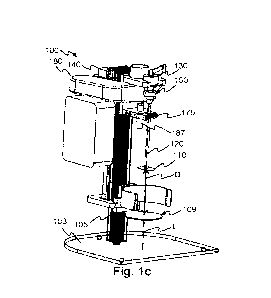
In Fig, lc, an alternative, or further, embodiment of the contrast agent mixer
100 is illustrated. In this embodiment, the holding arrangement 109 is movable
along
the longitudinal axis L of the mixer shaft 120. The movement of the holding
arrangement 109 may be controlled by the second motor arrangement 140
similarly to
the movement of the mixer blade 110 along the longitudinal axis L, e.g., by
means of
rotating of motor shaft 14.
In Fig. id, a side view of the mixer 100 according to some embodiments
wherein the connection between the motor shaft 145 and the holding arrangement
109 is
visible. The holding arrangement 109 is in this embodiment movable along the
column
CA 03229594 2024-02-16
WO 2023/048623 PCT/SE2022/050833
105 of the mixer such that the distance D between the holding arrangement 109
and the
mixer blade 110 is changed.
It should be mentioned that in some embodiments (not shown), the second
motor arrangement 140 may be configured to control a vertical positon of the
both the
5 holding arrangement 109 and the mixer blade 110. This may be provided by
the second
motor arrangement 140 being configured to move one of the mixer blade 110 and
the
holding arrangement in a first vertical direction, and the other of the motor
arrangement
140 and the mixer blade 110 in a second vertical direction, the second
vertical direction
being opposite the first vertical direction. In some embodiments, one or more
clutch
10 arrangements are provided between the second motor arrangement 140 and
one or both
of the mixer blade 110 and the holding arrangement 109. In such embodiments,
the
second motor arrangement 140 may be configured to selectively control the
vertical
positon of the mixer blade 110 and/or the holding arrangement 109.
In Fig. le, another embodiment of the contrast agent mixer 100 is shown in a
15 side view corresponding to that of Fig. lb. In this embodiment, the
contrast agent mixer
is similar to the contrast agent mixer 100 of the previous embodiment in every
aspect
except that it does not comprise a movable holding arrangement 109. It may
comprise a
fixed holding arrangement (not shown). This means that the second motor
arrangement
140 controls a vertical positon of the mixer blade 110 along the longitudinal
axis L.
This implies that, when the vertical position of the mixer blade 110 is
controlled, the
first motor arrangement 130 is moved together with the mixer blade 110.
It should be mentioned that by changing the distance D between the holding
arrangement 109 and the mixer blade 110 by moving the holding arrangement 109
along the longitudinal axis of the mixer shaft 120 may be beneficial as it
reduces
vibrations and noise. This is due to e.g., that the rotatable mixer blade 110
may be more
securely fastened in this embodiment. However, changing the distance D between
the
holding arrangement 109 and the mixer blade 110 by moving the mixer blade 110
along
the longitudinal axis of the mixer shaft 120 may be beneficial as the second
motor
arrangement 140 may be reduced in size and weight and thereby reducing cost.
This is
due to e.g., that the holding arrangement 109 together with the mixing
container 200
CA 03229594 2024-02-16
WO 2023/048623 PCT/SE2022/050833
16
with liquid 3 and powder 5 is, in most embodiments, heavier than the
corresponding
movable parts associated with the mixer blade.
The second motor arrangement 140 may be a stepper motor 140. The first
motor arrangement 130 may be a brushless DC motor 130.
It should be emphasized that although the embodiment in Figs. la and lb is
described as the mixer blade 110 being movable along the longitudinal axis L
of the
mixer shaft 120, and the embodiment in Figs. lc and id is described as the
holding
arrangement 109 being movable along the longitudinal axis L of the mixer shaft
120,
these embodiments are not mutually exclusive. The skilled person will
understand that
embodiments wherein both the mixer blade 110 and the holding arrangement 109
are
movable along the longitudinal axis L and that the second motor arrangement
140 may
be configured with e.g., gearing and/or clutches to facilitate this mutual
movement. In
summary, either one of or both of the mixer blade 110 and the holding
arrangement 109
are movable along the longitudinal axis L such that the distance D between the
holding
arrangement 109 and the mixer blade 110 is changed. It should be mentioned
that in
embodiments wherein the mixer 100 does not comprise a specific holding
arrangement
109, movable or stationary, the distance D between the holding arrangement 109
and
the mixer blade 110 is to be interpreted as a distance between the mixer blade
110 and a
surface for supporting the mixing container 200. Such a surface may be e.g.,
the base
103 or a table on which the mixer 100 is placed.
The mixer shaft 120 may in some embodiment be connected to the first motor
arrangement 130 by means of a clutch 150. The clutch 150 is beneficial as it
may be
configured to allow simple and quick connection and disconnection of the mixer
blade
110 to the mixer 100. If, for instance, the mixer blade 110 is reusable, it
may be easily
.. removed and cleaned. Additionally, if the mixer blade 110 is disposable, it
may be
easily removed and replaced. It should be mentioned that the mixer blade 110
may,
depending on embodiment, be interpreted as comprising also the mixer shaft
120. In one
embodiment, the mixer blade 110 is a stainless steel mixer blade 110 which is
beneficial
as it is easy to clean and durable. In another embodiment, the mixer blade 110
is a
plastic mixer blade 110 which is beneficial as it reduces the need of
cleaning.
CA 03229594 2024-02-16
WO 2023/048623 PCT/SE2022/050833
17
The clutch 150 may be formed in any suitable way that allows release of the
mixer blade 110 from the first motor arrangement 130. With reference to Figs.
2a to 2d,
one preferred embodiment of the clutch 150 will be explained in further
detail. In this
embodiment, the clutch 150 comprises an upper member 153 and a lower member
156.
The upper member 153 is operatively connected to the first motor arrangement
130 and
the lower member 156 operatively connected to the mixer blade 110. The
operative
connection of the lower member 156 to the mixer blade 110 may be via the mixer
shaft
120. The operative connection of the upper member 153 to the first motor 130
may
comprise a drive shaft 135 of the first motor arrangement 130. The upper
member 153
and the lower member 156 may, as best illustrated in the cross sectional view
of Fig. 2b,
be connected to respective shaft 135, 120 by any suitable fastening means 152
or
formed integral with the shafts 135, 120. The upper member 153 and the lower
member
156 are detachably attached to each other by one or more attachment means 155,
see
Figs. 2c and 2d illustrating the upper member 153 and the lower member 156
separated.
The attachment means 155 may be any suitable attachment means 155 such as a
bayonet
mount, a click mount, nut and bolt configuration etc. One of the upper member
153 or
the lower member 156 may be formed with guiding protrusions (not shown) and
the
other of the upper member 153 and the lower member 156 with mating notches
(not
shown).
However, in order to keep the surfaces of the upper member 153 and the lower
member 156 smooth and avoid difficult cleaning and buildup of dirt, the
attachment
means 155 are in a preferred embodiment formed as magnets 155. The attachment
means 155 may be one single magnet 155 provided in either of the upper member
153
or the lower member 156 provided that the other of the upper member 153 or the
lower
member 156 is magnetic. As the upper member 153 will transfer rotation about
the
longitudinal axis L of the mixer shaft 120, the clutch 150 will be subjected
to torque;
and the attachment means 155 has to be sufficiently strong to withstand this.
The
torque, and also Euler forces, subjected to the clutch 150 will depend on an
acceleration
provided by the first motor arrangement 130. A comparably weaker attachment
means
155 may be compensated by configuring the controller 160 to reduce the torque
exerted
by the first motor 130. The inventors behind this disclosure have realized
that a
CA 03229594 2024-02-16
WO 2023/048623 PCT/SE2022/050833
18
sufficiently strong clutch 150 is provided by arranging a plurality of magnets
155 at
each of the upper member 153 and the lower member 156. Preferably the magnets
155
are embedded in cavities of the upper member 153 and the lower member 156 and
arranged such that, when the clutch 150 is assembled, a south pole of magnets
155 in
the upper member 153 face a north pole of magnets 155 the lower member 156 or
vice
versa. In a preferred embodiment, the upper member 153 and the lower member
156 is
provided with three magnets each.
The magnets 155 and their associated cavities are preferably covered with a
suitable coating to reduce the presence of hard to clean nooks and crannies.
As seen in the cross sectional view of the clutch 150 as presented in Fig. 2b
and in the isolated views of the upper member 153 in Fig. 2c and the lower
member 156
in Fig. 2d, the lower member 156 may be formed with a convex shape and the
upper
member 153 with a mating concave shape. Although not illustrated, the opposite
setup
is also possible wherein the upper member 153 is formed with a convex shape
and the
lower member 156 with a mating concave shape although the convex shape is
easier to
clean and preferred for the lower member 156.
It should be noted that albeit shown together, the attachment means 155
provided as magnets 155 and the shape of the upper member 153 and the lower
member
156 are not directly linked and e.g., any suitable attachment means 155 may be
combined with any suitable shape of the upper member 153 and the lower member
156.
Additionally, or alternatively, as previously mentioned, the mixer blade 110
may be removable from the mixer shaft 120. In such embodiments, the mixer
blade 110
may be attached to the mixer shaft 120 by means of e.g.õ a twist lock, a snap-
in or other
suitable attachment means. Such arrangements are beneficial as the mixer blade
110 and
the mixer shaft 120 may be provided from different materials. In one
embodiment, the
mixer blade 110 is a plastic mixer blade 110 and the mixer shaft 120 is a
metal mixer
shaft. The mixer blade 110 may be a disposable mixer blade 110 and the mixer
shaft
120 may be a reusable mixer shaft 120.
With reference to Figs. 3a and 3b, in order to ensure a consistent and
efficient
foaming of the negative contrast agent foam 7, the inventors behind this
disclosure has,
through inventive thinking, concluded that the mixer blade 110 is preferably
arranged
CA 03229594 2024-02-16
WO 2023/048623
PCT/SE2022/050833
19
on the mixer shaft 120 such that a blade angle a is formed between a plane PB
of the
mixer blade 110 and a reference plane PR. Wherein the reference plane PR is
perpendicular to the longitudinal axis A of the mixer shaft 120. A large blade
angle a
will incorporate more air compared to a small blade angle a and thus provide a
larger
foam 7 volume assuming all other conditions are the same. Substantive research
and
experimenting has concluded that a blade angle a in the range of 0,5 to 5
provides an
acceptable per-oral negative contrast agent foam 7 for abdominal CT. If the
blade angle
a is within the range of 2 to 4 , a better contrast agent foam 7 is provided
and a blade
angle at substantially 3 has been shown to be most preferable.
The mixer blade 110 may be formed in various shapes, but experimental tests
and research has concluded that a homogenous mixer blade 110 provides a
suitable
negative contrast agent foam 7. Adding holes or cavities to the mixer blade
110 reduces
the effect of the mixing blade 110 as the increased turbulence caused by the
holes
provides a foam 7 that is less homogeneous and with many visible bubbles
compared to
a homogenous mixer blade 110. Further to this, the mixer blade 110 may be
formed in a
substantially circular circumferential shape, preferably with the mixer shaft
120
centered on the mixer blade 110 as this provides a balanced load and reduces
the risk of
vibrations when the mixer blade 110 is rotated. A lower surface of the mixer
blade 110
may comprise a bulge, or a stud. The lower surface may be saucer shaped. This
is
beneficial as it facilitates more turbulence during operation of the mixer
100, which is
advantageous for mixing and foam formation.
With reference to Figs. 4a and 4b, the movement of the mixer blade 110 and/or
the holding arrangement 109 along the longitudinal axis L will be explained in
further
detail. The mixer blade 110 and/or the holding arrangement 109 is preferably
moved
repeatedly up and down such that a vertical distance Lp between the mixer
blade 110
and the holding arrangement 109 is shifted between an upper distance Lu and a
lower
distance LL along the longitudinal axis L. This may be provided by the
controller 160
controlling the second motor arrangement 140 to move the mixer blade 110
and/or the
holding arrangement 109 up and down along the longitudinal axis L of the mixer
shaft
120. At the lower distance LL, the mixer blade 110 is preferably located close
to a
bottom of the mixing container 200 but may for various reasons be distanced
from the
CA 03229594 2024-02-16
WO 2023/048623
PCT/SE2022/050833
bottom of the mixing container 200. In some embodiments, at the upper distance
Lu, the
mixer blade 110 is fixed at a height of approximately half the height of the
mixing
container 200. In other embodiments, the upper distance Lu between the mixer
blade
110 and the holding arrangement 109 is determined based on a wanted height of
the
5 negative contrast agent foam 7 in the mixing container 200. In one
embodiment, the
upper distance Lu of between the mixer blade 110 and the holding arrangement
109 is
below 751%0 of a wanted height of the negative contrast agent foam 7,
preferably below
65 /0 of the wanted height of the negative contrast agent foam 7, and most
preferably
below 55 % of the wanted height of the negative contrast agent foam 7 in the
mixer
10 container 200. In some embodiments, the upper distance Lu is adapted
based on a
current height of the negative contrast agent foam 7 in the mixing container
200. The
upper distance may be adapted to be below 75%, preferably below 65 %, and most
preferably below 55 % of the current height of the negative contrast agent
foam 7 in the
mixer container 200.
15 As seen
in Fig. 4b, the controlling 320 of the vertical distance LP between the
mixer blade 110 and the holding arrangement 109 may be done with a
substantially
constant movement such that the vertical distance Lp between the mixer blade
110 and
the holding arrangement 109 plotted over time will describe a sawtooth curve
indicted
by the solid line of Fig. 4b. Alternatively, the controlling 320 of the
vertical distance LP
20 between the mixer blade 110 and the holding arrangement 109 may be done
with a
substantially sinusoidal movement such that the vertical distance Lp between
the mixer
blade 110 and the holding arrangement 109 plotted over time will describe a
sinusoidal
curve, indicated by the dotted line of Fig. 4b.
Through further research and experimental efforts, the inventors behind this
disclosure have concluded that there are further design features of the mixer
blade 110
that may be utilized to further improve the quality of the negative contrast
agent foam 7.
In Fig. 5, a vertical thickness T of the mixer blade 110 is indicated and the
mixer blade
thickness T has been shown to affect the size of the bubbles of the negative
contrast
agent foam 7. Reducing the thickness T of the mixer blade 110 will reduce the
size of
the bubbles. Reducing the thickness T too much may make the mixer blade 110
too
flexible and it may bend or otherwise deformed during handling. The mixer
blade 110 is
CA 03229594 2024-02-16
WO 2023/048623 PCT/SE2022/050833
21
in one embodiment configured with a thickness T of 0,4 to 1,8 mm, and in a
further
embodiment with a thickness of 0,5 to 1,1 mm and in an even further
embodiment, a
thickness T of from (and including) 0,7 to (and including) 1,0 mm. It should
be noted
that the size of the bubbles of the foam 7 will depend on other factors such
as the
rotational speed of the mixer blade 110.
With reference to Fig. 6, one further feature of the present disclosure will
be
explained. In order to incorporate a controllable volume of air when mixing
the dry
powder 5 and the liquid 3, a size of the mixer blade 110 in relation to the
mixing
container 200 is preferably controlled. Fig 5 is a top view of the mixing
container 200
with the mixer blade 110 substantially centered in the mixing container 200.
The mixer
blade 110 exhibits a projected diameter D's in the reference plane PR. That
is, assuming
a circular mixer blade 110 having a diameter DB (see Fig. 3a), this would
result in a
projected diameter D'B of the mixer blade 110 in the reference plane PR equal
to the
diameter Da of the mixer blade 110 multiplied by the cosine value of the blade
angle a,
D'B = DB = cos(a). The mixing container 200 correspondingly exhibits a
diameter Dc in
the reference plane P. Research and experimental efforts by the inventors of
this
disclosure have resulted in the teaching that a ratio of the diameter Dc of
the mixing
container 200 and the projected diameter D'B of the mixer blade 110 in the
reference
plane PR, Dc/D'B, of between 2 and 3 allows for a good incorporation of air in
the foam
7. Preferably, the diameter Dc of the mixing container 200 is between 2,4 and
2,7 times
larger than the projected diameter D's of the mixer blade 110 in the reference
plane PR,
most preferable about 2,5 times.
Generally, a diameter ratio between the mixer blade 120 and the mixing
container 200 may be in the range of 0,3 to 0,7, preferably around 0.4. As an
example,
the diameter DB of the mixer blade 120 may be in the range of 35 mm to 60 mm,
preferably 40 mm to 55 mm, more preferably 48 mm, and the diameter Dc of the
mixing container 200 may be 80-200 mm, preferably between 100-130 mm. A
diameter
of a bottom of the mixing container bottom may however be smaller, for
instance 40-70
mm.
In one embodiment of the negative contrast agent mixer 100, presented in a
perspective view in Fig. 7, it further comprises a liquid container 180
arranged to
CA 03229594 2024-02-16
WO 2023/048623 PCT/SE2022/050833
22
dispense the liquid 3 into the mixing container 200. The liquid container 180
may be of
any suitable shape, size or form and is not limited to the tubular shape as
illustrated in
Fig. 7. The liquid container 180 is preferably operatively connected to a tube
member
187 arranged to guide the liquid 3 from the liquid container 180 to the mixing
container
200. In one further embodiment, a valve 185 is arranged to control the flow of
liquid 3
from the liquid container 180 into the mixing container 200. The valve 185 may
be
arranged between the liquid container 180 and the tube member 187. The valve
185 is
controllable between an open and a closed position and in one embodiment, the
controlling of the position of the valve 185 is provided by the controller
160. The valve
185 may be controllable in one or more discrete steps or continuously and step-
less
between the open position and the closed position. The liquid container 180
may
optionally be provided with one or more sensors (not shown) configured to
detect a
presence of liquid 3 in the liquid container 180.
In alternative, or additional, embodiments of the mixer 100, it may further
comprise a powder container 181 (see Figs. 8a-b) arranged to dispense the
contrast
powder 5 into the mixing container 200. In one embodiment, the powder
container 181
is pivotably connected to the mixer 100 and controllable between a tilted
position, at
which the contrast powder 5 is dispensed into the mixing container 200, and an
upright
position, at which the contrast powder 5 is stayed in the powder container
181. The
control of the powder container 181 is preferably provided by the controller
160. The
powder container 181 may also be operatively connected to a tube member (not
shown)
for guiding the powder into the mixing container. The release of the contrast
powder 5
into the tube member may be controlled by e.g., a hinged trap-door
configuration. The
pivoted connection and the hinged trap-door configuration are referred to as a
powder
dispenser 183, see Fig. 9. The powder dispenser 183 is consequently arranged
between
the mixing container and the powder container 181 in a path of the contrast
powder 5.
Fig. 7 further illustrates a clip member 109 of the holding arrangement 109
that
in this embodiment is attached to the column 105. It should be emphasized
that, as
previously explained, the holding arrangement 109 may alternatively be
connected to
the second motor arrangement 140 such that it is movable along the
longitudinal axis L
of the mixer shaft 140. However, in embodiments in which only the mixer blade
110 is
CA 03229594 2024-02-16
WO 2023/048623 PCT/SE2022/050833
23
movable along the longitudinal axis L of the mixer shaft L, the holding
arrangement
may e.g., be attached to the column 105 as illustrated in Fig. 7, or form part
of the base
103. The clip member 109 is usable to hold the mixing container 200 in
position during
operation of the mixer 100.
In order to ensure that the mixer shaft 120 is in position and correctly
balanced,
the carrier 170 may be provided with a guide member 175 arranged distanced
from the
first motor arrangement 130 and the clutch 150. The guide member 175 is
provided to
guide the mixer shaft 120 and to ensure its centration in the mixing container
200. The
guide member 175 may be provided with a locking member 175' arranged to secure
the
mixer shaft 120 in e.g., a notch in the guide member 170 such that the mixer
shaft 120
may rotate freely about the longitudinal axis L of the mixer shaft 120 but it
is not
permitted to form an angle to the longitudinal axis L. The locking member
175', the
guide member 175 and/or a notch of the locking member 175' and/or the guide
member
175 may be provided with bearings or other suitable friction reducing means
allowing
the mixer shaft 120 to rotate freely even though it is guided by the guide
member 175
and optionally the locking member 175'.
The mixing container 200 as illustrated in Fig. 7 further comprises a
removable
lid 210. This lid 210 is provided to reduce spill and splatter of the liquid 3
and/or the
foam 7. The lid 210 is provided with an opening 215 configured to allow the
mixer
blade 110 to enter the mixing container 200.
It should be mentioned that the mixing container 200 may be any vessel
suitable for holding the liquid 3, the powder 5 and allowing them to be mixed
into a
foam. The mixing container 200 may be a glass, metal or plastic container and
in a
preferred embodiment, the mixing container is a paper material mixing
container 200.
In further embodiments, the guide member 175 may further be configured to
form a guide for the tube member 178 for the liquid container 180 and/or the
powder
container 181.
In Figs. 8a and 8b, perspective views of the mixer 100 is presented
illustrating
an embodiment where the mixer 100 comprises an outer housing 101. The outer
housing 101 may be made from any suitable material and in one embodiment the
outer
housing 101 is a plastic casing allowing the mixer 100 to, in at least some
countries, be
CA 03229594 2024-02-16
WO 2023/048623
PCT/SE2022/050833
24
powered by main power without a need for protective ground. The outer housing
101
makes the mixer 100 esthetically pleasing, dampens sounds from the mixer 100,
reduced the risk of splashes, provides protection for the mixer 100 etc. The
outer
housing 101 is preferably provided with an openable door 101', illustrated in
Fig, 8b,
that may be opened to provide access to the mixing container 200 and the mixer
blade
120. The liquid container 180 is preferably accessible from outside the outer
housing
101. The door 101' may of a different type of material than the other parts of
the outer
housing 101. In one embodiment, the door 101' is a transparent plastic door
101'
allowing a user of the mixer 100 to see the forming of the foam 7.
The mixer 100 may be provided with a user interface 190. The user interface
190 may be controlled by the controller 160 and may be used to communicate
operational data to a user of the mixer 100 and also to receive operational
data from the
user. In one embodiment, the user interface 190 is an illuminated button 190.
When the
button 190 is pressed, the mixer 100 is started and a color of the
illumination indicate
the status of the mixer 100. Different illumination colors and patterns may be
utilized to
indicate different states and/or different requested actions from the user.
Such states and
actions may be, but are not limited to, an off state where the mixer 100 is
unpowered, an
idle state where the mixer 100 is ready to use, a state wherein the door 101'
is open, a
state wherein the mixing container 200 is missing, a state wherein the liquid
container
180 is empty, a state wherein the powder container 181 is empty, a mixing
state wherein
mixing is in process, a mixing completed state etc.
As illustrated in Fig. 8c, a partial block diagram of the mixer 100 according
to
some embodiments, the mixer 100 may be provided with one or more external
interfaces 195. These external interfaces 195 may be one or more of any
suitable wired
or wireless interfaces e.g., serial interfaces (RS232, USB etc.), parallel
interface (IEEE
1284 etc.), WiFi, cellular interface (GSM, UMTS, LTE, NR etc.), Bluetooth
(BLE), low
power WAN (LoRa, Sigfox etc.), etc. The external interface 195 may be
configured to
allow the mixer to be connected to other devices directly or via e.g., a cloud
service
forming part of an Internet of Things, IoT network. The mixer 100 may be
configured
to, preferably by means of the controller 160, to communicate with a server in
order to
share a current operational status, receive control commands and/or receive
software or
CA 03229594 2024-02-16
WO 2023/048623 PCT/SE2022/050833
configurational updates. The current operational status may comprise one or
more of a
number of mixing cycles performed, any error messages, current amount of
liquid in the
liquid container 180, current amount of powder in the liquid container 180,
any need for
maintenance etc. The data provided by the mixer 100 may be used to schedule
5 maintenance of the mixer 100, place orders for powder and/or liquid etc.
The control
commands received through the external interface 195 may be service commands,
start
commands, stop commands etc. The control commands may be provided from a cloud
service or directly to the mixer via e.g., Bluetooth. The external interface
allows for
remote and/or touchless control of the mixer by e.g., a mobile device.
10 The mixer 100 may further be provided with one or more sensors 165.
Sensors
165 may be provided to detect an amount of liquid 3 added to the mixing
container 200,
an amount of contrast powder 5 added to the mixing container 200, a status of
the
foaming of the negative contrast agent foam 7, a height of the foam 7 in the
container
200, a weight of the container 200, a level of liquid 3 in the liquid
container 180, a level
15 of contrast powder 5 in the powder container 181, a rotational speed of
the mixer blade
110, a presence of the mixer blade 110, a closure of the locking member 175',
a
presence of the mixing container 200, the vertical distance Lp between the
mixer blade
110 and the holding arrangement 109 etc. The sensors 165 may be any type of
suitable
sensor 165 such as, but not limited to, switches, optical sensors, pressure
sensors,
20 ultrasonic sensors, accelerometers, current sensors, voltage detectors
etc. The controller
160 is preferably operatively connected to the sensors 165 and configured to
control the
operation of the mixer 100 based on data provided by the sensors 165.
In one embodiment, the controller 160 is configured to control, based on data
from one or more sensors 165, an amount of liquid 3 added to the mixing
container 200.
25 In a further, or alternative embodiment, the controller 160 is
configured to control,
based on data from one or more sensors 165, an amount of powder 5 added to the
mixing container 200.
With reference to Fig. 9, a mixer system 10 is shown. The mixer system
comprises the negative oral contrast agent mixer 100 as presented herein, the
mixing
container 200 as previously introduced, the contrast powder 5 and the liquid
3. As
presented, the mixing container 200 is arrangeable to receive the mixer blade
110 of the
CA 03229594 2024-02-16
WO 2023/048623 PCT/SE2022/050833
26
mixer 100. The liquid 3 may be provided in the liquid container 180 and
dispersed in
the mixing container 200 under control of the controller 160. The contrast
powder 5
may be provided in the powder container 181 and dispersed in the mixing
container 200
under control of the controller 160. The mixer system 10 is configured to
provide the
per-oral negative contrast agent foam 7 for abdominal CT as described herein.
With reference to Fig. 10 a method 300 for providing a per-oral negative
contrast agent foam 7 for abdominal CT will be presented. The method 300 may
be
performed by any suitable means configured to control a vertical distance Lp
between a
mixer blade and a holding arrangement and the rotational speed of the mixer
blade, but
.. is preferably performed by the controller 160 of the negative oral contrast
agent mixer
100 as disclosed herein. The mixer blade 110 is configurable to mix the
contrast powder
5 with the liquid in the mixing container 200. The method 300 comprises
controlling
310 the mixer blade 110 to rotate at a wanted rotational speed. This may be
provided by
the controller 160 controlling the first motor arrangement 130 to rotate at
the wanted
rotational speed. It may further comprise accelerating, for a predetermined or
configurable acceleration time period, the rotational speed mixer blade 110
until it
reaches the wanted rotational speed. This is beneficial as it reduces the wear
of the first
motor arrangement 130 and also the risk of splashes of the liquid due to
sudden changes
in rotational speed of the mixer blade 110. In one embodiment, the wanted
rotational
speed is in the range of 6500 to 10000 rpm, preferably in the range of 8000 to
8500
rpm. It should be mentioned that the wanted rotational speed may very well be
different
at different stages of the method 300. In one embodiment, the rotational speed
of the
mixer blade 110 is lower at a start of the method 300 than at the end of the
method 300.
As the dispersion will have a different viscosity compared to the negative
contrast agent foam 7, it is beneficial to control 310 a current of the first
motor
arrangement 130 when controlling the rotational speed of the mixer blade 110.
This
ensures a constant rotational speed of the first motor arrangement 130
regardless of the
load presented to the mixer blade 110.
The method 300 further comprises controlling 320 the vertical distance Li'
between the mixer blade 110 and the holding arrangement to repeatedly change
between
the upper distance Lu and the lower distance LL along the longitudinal axis L
of the
CA 03229594 2024-02-16
WO 2023/048623 PCT/SE2022/050833
27
mixer shaft 120. This may be provided by the controller 160 controlling the
second
motor arrangement 140 to move the mixer blade 110 and/or the holding
arrangement
109 up and down along the longitudinal axis L of the mixer shaft 120. The
controlling
320 of the vertical distance LP between the mixer blade 110 and the holding
.. arrangement may, as described in reference to Fig. 4b, be done with a
substantially
constant movement such that the vertical distance Lp between the mixer blade
110 and
the holding arrangement 109 plotted over time will describe a sawtooth curve.
Alternatively, the controlling 320 of the vertical distance Li' between the
mixer blade
110 and the holding arrangement 109 may be done with a substantially
sinusoidal
movement such that the vertical distance LP between the mixer blade 110 and
the
holding arrangement 109 plotted over time will describe a sinusoidal curve.
It should be mentioned that controlling 320 the vertical distance LP between
the
mixer blade 110 and the holding arrangement 109 to repeatedly move between the
upper distance Lu and the distance LL may be performed a predefined or
configurable
number of times. In one embodiment of the method 300, the vertical distance LP
between the mixer blade 110 and the holding arrangement 109 is cycled between
the
upper distance Lu and the lower distance LL at least 8 times, and in a
preferred
embodiment, the vertical distance Lp between the mixer blade 110 and the
holding
arrangement 109 is repeated at least 12 times. Alternatively, or additionally,
the vertical
distance Lp between the mixer blade 110 and the holding arrangement 109 is
cycled
between the upper distance Lu and the lower distance LL less than 25 times,
and in a
preferred embodiment, the movement of the vertical distance Lp between the
mixer
blade 110 and the holding arrangement 109 is cycled less than 17 times. The
speed of
the vertical movement of the mixer blade 110 and/or the holding arrangement
109 is
preferably such that the desired number of cycles is executed in less than 4
minutes,
preferably in between 2 and 3 minutes.
In some embodiments, the wanted rotational speed of the mixer blade 110 is
different depending on the vertical distance Lp between the mixer blade 110
and the
holding arrangement 109. In a preferred embodiment, the wanted rotational
speed of the
mixer blade 110 is lower at the lower distance LL than at the upper distance
Lu between
the mixer blade 110 and the holding arrangement 109.
CA 03229594 2024-02-16
WO 2023/048623 PCT/SE2022/050833
28
In embodiments of the mixer 100 wherein it comprises the liquid container 180
and the valve 185, the method 300 may further comprise controlling 302 the
valve 185
to dispense liquid 3 into the mixing container 200. The controlling 302 of the
valve 185
may be done subsequent to initiating the control 310 of the mixer blade 110 to
rotate at
the wanted rotational speed or before initiating the control 310 of the mixer
blade 110 to
rotate at the wanted rotational speed.
Similarly, in embodiments of the mixer 100 wherein it comprises the powder
container 181 and the powder dispenser 183, the method 300 may further
comprise
controlling 303 the powder dispenser 183 to dispense the contrast powder 5
into the
mixing container 200. The controlling 303 of the powder dispenser 183 may be
done
subsequent to initiating the control 310 of the mixer blade 110 to rotate at
the wanted
rotational speed or before initiating the control 310 of the mixer blade 110
to rotate at
the wanted rotational speed.
In order to reduce the risk of buildup of large bubbles of air in the foam 7,
it
may be beneficial to pause the rotation of the mixer blade 110 for a period to
allow any
oversized bubbles to raise to a surface of the foam 7 and collapse. This may
be provided
by stopping 315 the rotation of the mixer blade 110 for a rest period.
The method 300 may, as the skilled person will understand after digesting the
teachings of this disclosure, be modified to comprise reading data from any of
the
.. sensors mentioned in this disclosure. The method 300 may comprise ensuring
that liquid
3, contrast powder 5, the mixing container 200 etc. is present before
initiating the
mixing. The method 300 may be executed until a sensor indicate that sufficient
foaming
is accomplished.
Modifications and other variants of the described embodiments will come to
.. mind to one skilled in the art having benefit of the teachings presented in
the foregoing
description and associated drawings. Therefore, it is to be understood that
the
embodiments are not limited to the specific example embodiments described in
this
disclosure and that modifications and other variants are intended to be
included within
the scope of this disclosure. For example, while embodiments of the invention
have
been described with reference to a negative oral contrast agent mixer with
related
methods and systems, persons skilled in the art will appreciate that the
embodiments of
CA 03229594 2024-02-16
WO 2023/048623
PCT/SE2022/050833
29
the invention can equivalently be applied to mixing of other agents where a
homogenous and controlled foaming is desired. Furthermore, although specific
terms
may be employed herein, they are used in a generic and descriptive sense only
and not
for purposes of limitation. Therefore, a person skilled in the art would
recognize
numerous variations to the described embodiments that would still fall within
the scope
of the appended claims. Furthermore, although individual features may be
included in
different claims (or embodiments), these may possibly advantageously be
combined,
and the inclusion of different claims (or embodiments) does not imply that a
combination of features is not feasible and/or advantageous. In addition,
singular
references do not exclude a plurality. Finally, reference signs in the claims
are provided
merely as a clarifying example and should not be construed as limiting the
scope of the
claims in any way.