Note : Les descriptions sont présentées dans la langue officielle dans laquelle elles ont été soumises.
WO 2023/151859
PCT/EP2022/088084
1
Liquid target system
Technical field of the invention
The present invention relates to the field of radio-isotopes. More
specifically, the
present invention relates to a liquid target system for the production of
radio-isotopes,
as well as to the use thereof and a corresponding method.
Background of the invention
For the production of radio-isotopes, generally, solid targets are being used
for
their high yield in state-of-the-art systems, as for solid targets, a large
density of a parent
nuclide, from which the radio-isotopes, may be easily achieved. Indeed, a
drawback of
using a liquid targets is the limited solubility of most parent nuclide
compounds in water
(typically used as the liquid solvent) at room temperature. For example, salts
of Ra-226,
which may be used as basic chemicals for providing the parent nuclide for
producing
the radio-isotope Ra-225 that may decay to the radio-isotope Ac-225, have a
limited
solubility in water. By way of illustration, radium nitrate salt Ra(NO3)2 has
a solibulity of
13.9g per 100g of H20 at 20 C.
However, one advantage of using a liquid target rather than a solid target is
that
less (or no) liquid to solid and solid to liquid conversions are required in
the chemical
process for separating the radio-isotopes from the target. This chemical
process step
typically has a large risk on (uncontrolled) losses of radio-isotopes and
radio-active
waste generation. No such conversion is required for liquid targets, which is
a huge
advantage of such targets.
Furthermore, the potential disadvantage of a low parent nuclide concentration
in liquid targets must be placed in perspective. As an example, the production
of Ra-
225 from Ra-226 via a photonuclear reaction is considered. The production of
Ra-225
in function of time may depend on electron beam current (mA), electron energy
(MeV),
converter design and target design. Herein, the converter is designed for
stopping the
high energy electrons and producing high energy Bremsstrahlung photons that
are
needed for the photonuclear reaction. The more high energy photons that are
produced,
and the more Ra-226 directly in front of the photon beam, the more Ra-225 will
be
formed. However, assuming an electron-to- Bremsstrahlung photons conversion of
about 50%, still about half of the energy of the electrons may be deposited
into the
converter. The very high energy deposition in the small converter volume
associated
therewith can easily limit the production capacity, hence reducing the yield
of high
energy Bremsstrahlung photons.
CA 03232148 2024- 3- 18
WO 2023/151859
PCT/EP2022/088084
2
One way to deal with this is to have a plurality of thin slices of converter
material
separated by cooling means, and, in addition, to raster the electron beam over
a larger
surface area of the converter. However, the larger surface area will
inevitable have a
negative influence on the production rate. The consequence of a larger
converter
surface area is that Ra should be divided over the entire surface area where
the high
energy gammas are present, while the highest yields are obtained by
positioning the
Ra as close to the converter as possible. This can be considered a drawback
for any
kind of solid target, as the high density that can be achieved (e.g. 3-5
g/cc), cannot be
optimally exploited when the current density of the converter is the limiting
factor (e.g.
0.125 - 0.25 mA/cm2), and the surface to volume ratio needs to be increased.
US 2014/0362964 Al describes an isotope production system configured to
irradiate a starting liquid with a particle beam for generating radioisotopes
and for
transforming a portion of the starting liquid into vapor.
There are, therefore, a few drawbacks associated with solid targets.
Nevertheless, the efficiency and yield of liquid targets is generally very
low, so that in
the state of the art, the focus remains on solid targets. There is, thus,
still a need in the
art for devices and methods that may improve the efficiency and the yield of
liquid target
systems.
Summary of the invention
It is an object of the present invention to provide a good liquid target
system. It
is a further object of the present invention to provide a good method for
producing radio-
isotopes.
The above objective is accomplished by a method and apparatus according to
the present invention.
It is an advantage of embodiments of the present invention that the yield and
production of radio-isotopes may be comparable to that of a solid target. It
is a further
advantage of embodiments of the present invention that the amount of parent
nuclide
material needed for obtaining a certain amount of radio-isotopes is limited.
It is still a
further advantage of embodiments of the present invention that liquid targets
are
provided allowing production of radio-isotopes with low radio-active waste
generation.
It is an advantage of embodiments of the present invention that the liquid
target
system may be continuously and efficiently cooled, thereby preventing
overheating of
the liquid target. It is a further advantage of embodiments of the present
invention that
the liquid target system allows for evacuating the heat in a steady-state,
continuous and
reliable way.
CA 03232148 2024- 3- 18
WO 2023/151859
PCT/EP2022/088084
3
It is an advantage of embodiments of the present invention that the liquid
target
may have a large total volume, so that adverse effects expected from losses
by, e.g.,
hydrogen formation or uncondensed water, may be limited. It is a further
advantage of
embodiments of the present invention that the liquid target system may be safe
to
operate. It is still a further advantage of embodiments of the present
invention that
operation of the liquid target can be monitored, e.g., by accurately tracking
the
temperature and/or pressure, which is often difficult for solid targets.
In a first aspect, the present invention relates to a liquid target system for
the
production of radio-isotopes. The liquid target system comprises a boiling
chamber for
containing the liquid and basic chemicals from which the radio-isotopes can be
produced using irradiation. The boiling chamber comprises an irradiation
window for
allowing the liquid and basic chemicals to be irradiated, causing the liquid
to evaporate
into vapor. The liquid target system is configured so that overheating of the
liquid target
is controlled by the thermodynamics of the evaporation process.
Where in embodiments of the present invention reference is made to an
irradiation window, reference is made to an area in the wall of the boiling
chamber that
allows the radiation required for irradiating the basic chemicals from which
the radio
isotopes can be produced to enter the boiling chamber. The type of irradiation
window
that is used may depend on the type of irradiation. For example, in the case
of the use
of gamma radiation, the wall may for example be transparent for the radiation
anyway.
In embodiments, the liquid target system being configured so that overheating
of the
liquid target is controlled by the thermodynamics of the evaporation process,
may
comprise that the liquid target system is configured to use evaporation of the
liquid for
preventing said overheating, preferably for controlling the temperature of the
liquid
target. Overheating of the liquid target may result in evaporation of
substantially all liquid
in the liquid target, so that the basic chemicals are boiled to dryness.
It is an advantage of embodiments of the present invention that, as
overheating
of the liquid target may be prevented, the liquid target system allows to
avoid release
of non-condensable gasses from the chemical materials, allows for avoiding
sintering
of the chemical materials and/or allows for avoiding formation of insoluble
chemical
materials. Said overheating may occur as a result of the large amount of
irradiation
energy deposited in the liquid target. In particular, the so-called pair
production reaction
contributes to heating up of the liquid target. In the pair production
reaction, a high
energy photon in the presence of a high Z nucleus (e.g., a parent nuclide Ra-
226) is
converted to an electron and a positron with remaining kinetic energy. As the
charged
particles, i.e., the electron and the positron, slow down (and anneal in the
case of the
CA 03232148 2024- 3- 18
WO 2023/151859
PCT/EP2022/088084
4
positron), they will release their kinetic energy inside the liquid target,
which is
transferred into heat.
It is an advantage of embodiments of the present invention that a cooling
circuit
for the liquid target system, controlled by pumps, wherein the liquid and
basic chemicals
are pumped in the cooling circuit, may not be required. It is a further
advantage of
embodiments of the present invention that large heat exchangers requiring a
large
contact area with the liquid target may be avoided, so that the amount of
liquid target
that is required can be limited.
It is an advantage of embodiments of the present invention that the system
allows for up-concentrating during operation. More particularly, whereas the
initial
concentration of the basic chemicals used for producing radio-isotopes in the
liquid at
the starting temperature may be limited due to the solubility in the solvent,
e.g. water,
and higher concentrations at this starting temperature would result in
precipitation, it is
an advantage of embodiments of the present invention that the concentration
can be
increased during heating up of the liquid target, in line with the increase of
the solubility
of the basic chemicals in the solvent, e.g. water. The later is established by
evaporation
of the solvent, whereas the basic chemicals are maintained in the irradiated
area.
In embodiments, the evaporated water may be stored in the system as steam
or as liquid.
In embodiments, the liquid target system further comprises a condensation area
positioned above the boiling chamber, the condensation area having walls for
condensing the liquid vapour into liquid condensate, wherein the liquid
condensate can
be systematically returned or provided to the boiling chamber. Such walls also
may be
referred to as cooling surfaces. In embodiments, the liquid target system is
configured
for systematically returning the liquid condensate into the boiling chamber,
e.g., by a
direct fluidic connection between the condensation area and the boiling
chamber, or by
dropping of liquid condensate from the condensation area (e.g., due to
gravity)
systematically into the boiling chamber.
In embodiments, the at least one condensate collecting area thus may be
positioned at the walls for condensing the vapor and may be provided with a
dripping
mechanism for systematically returning the condensate to the boiling chamber.
In preferred embodiments, the liquid target system further comprises at least
one condensate collecting area for collecting the liquid condensate, the at
least one
condensate collecting area being positioned outside the boiling chamber (i.e.,
the at
least one condensate collecting area and the boiling chamber are separated
from each
other), wherein the at least one condensate collecting area and the boiling
chamber are
CA 03232148 2024- 3- 18
WO 2023/151859
PCT/EP2022/088084
interconnected so as to act as communicating vessels. In embodiments, the at
least
one condensate collecting area and the boiling room are configured such that a
ratio of
a volume of the liquid condensate, i.e., the liquid, present in the at least
one liquid
condensate collecting area to a volume of the liquid present in the boiling
chamber is at
5 least 0.5, preferably at least 1, more preferable at least 2. In
embodiments, a ratio of an
area of a horizontal cross-section of the at least one condensate collecting
area to an
area of a horizontal cross-section of the boiling chamber is at least 0.5,
preferably at
least 1, more preferably at least 2. The dimensions of the system may be
selected so
as to obtain an up-concentration to a factor 2. It is an advantage of these
embodiments
that, as the basic chemicals may become concentrated in the boiling chamber,
and may
be absent in the at least one condensate collecting area, during functioning
of the liquid
target system, up-concentration of the basic chemicals in the boiling chamber
is
possible that reaches at least 50%, preferably at least 100%, preferably at
least 200%,
higher than an initial concentration of the basic chemicals when present in
all liquid,
including in any liquid present in the at least one condensate collecting
area.
In embodiments, the volume of the boiling chamber is from 5mL to 500 mL. In
embodiments, the total volume of the at least one condensate collecting area
is from
5mL to 500mL.
In embodiments, said interconnection between the boiling chamber and the at
least one condensate collecting area comprises a gap or a tubing. In
embodiments, an
inlet of the interconnection for letting liquid into the boiling chamber is
located near a
bottom of the boiling chamber, e.g., in a wall or in the bottom. Preferably,
said inlet is
located at a height in the boiling chamber below 25% of the height of the
boiling
chamber, preferably below 10% of the height of the boiling chamber, more
preferably
substantially at the bottom of the boiling chamber. In embodiments, a cross-
sectional
area of said interconnection, perpendicular to the nominal flow direction
within said
interconnection, is at most 10%, preferably at most 5%, more preferably at
most 2%, of
at least one, e.g., both, of a vertical or horizontal cross-sectional area of
the boiling
chamber.
By way of illustration, embodiments not being limited thereto, an example is
discussed below. For a target that receives for example 1200 W, with 50% of
energy
effectively used to convert liquid to steam, and a single opening of 0.2 cm2
(corresponding to a radius of about 2.5mm in a circular opening), the liquid
would travel
at a velocity of 1.33cm/s. The smaller the opening, the larger the veloity
will be. By using
a small section for the interconnection, counter flow is avoided from the
irradiation
chamber towards the condensate chamber. By selecting the section small enough,
the
CA 03232148 2024- 3- 18
WO 2023/151859
PCT/EP2022/088084
6
liquid is flowing uniformly in one direction with a sufficiently high
velocity. The length
and/or diameter of the interconnection can be designed to create a pressure
drop that
will create a liquid level difference. In some embodiments, the design is made
so as to
store the condensate above the irradiation chamber irradiation level. This
ensures that
most of the condensate will return to the irradiation chamber when the
irradiation and
thus the boiling tops. In this way the chemicals are diluted and precipitation
is avoided
when the solution cools down.
In alternative examples, the inlet may be positioned at the top of the system
and operate
via drips.
It is an advantage of these embodiments that heat dissipation in the liquid
target
system (and hence prevention of overheating) is guaranteed by the boiling and
condensing process of the liquid. The condensation area may be cooled by a
secondary
system that contains a cooling fluid not containing radioactive material. In
embodiments, the liquid target system further comprises a coolant fluid bath
and/or a
coolant fluid circulation secondary system for cooling the condensation area.
In
preferred embodiments, the condensation area and the at least one condensate
collecting area is at least partly surrounded by the coolant fluid circulation
secondary
system.
It is an advantage of embodiments of the present invention that the liquid
target
system may automatically act as a concentrator, so that the concentration of
basic
chemicals may be increased in the irradiated volume during the heating
process, and
the subsequent liquid evaporation, caused by the irradiation. Furthermore, as
the
solubility of the basic chemicals in the liquid typically increases with
temperature, the
liquid target may contain a high concentration of basic chemicals, without
precipitating,
allowing efficient production of the radio-isotopes. Indeed, since the
solubility of the
basic chemical materials from which the radio-isotopes are generated is
relatively low
at room temperature, it is an advantage that the concentration may be
increased during
the heating process caused by the irradiation, taking advantage of the higher
solubility
of the basic chemical materials in the liquid at higher temperature.
In embodiments, the system further comprises an irradiation beam generator
configured for irradiating the liquid and basic chemicals. Herein, the
irradiation beam
generator is typically located outside of the boiling chamber, and is
configured for
irradiating the liquid and basic chemicals through the irradiation window. In
embodiments, the irradiation beam generator is selected from: an electron beam
gun;
a gamma beam gun; a proton beam gun; and a neutron beam gun. In embodiments
comprising the electron beam gun or the proton beam gun, the irradiation beam
CA 03232148 2024- 3- 18
WO 2023/151859
PCT/EP2022/088084
7
generator may further comprise a converter for converting a charged particle
beam (i.e.,
electron beam or proton beam) into high energy Bremsstrahlung photons, which
form
the irradiation beam.
In embodiments comprising the at least one condensate collecting area, the
irradiation beam generator may be configured such that the irradiation beam
propagates from the irradiation beam generator located outside of the boiling
chamber,
through the irradiation window, into the boiling chamber, without passing
through the at
least one condensate collecting area. It is an advantage of embodiments of the
present
invention that any liquid in the at least one condensate collecting area is
not boiled,
thereby transforming liquid in the at least one condensate collecting area
into vapor.
This may result in up-concentration of the basic chemicals present in the at
least one
condensate collecting area, which may result in a reduction in concentration
of the basic
chemicals in the boiling chamber. It is a further advantage of these
embodiments that
the irradiation beam may not be attenuated by absorption by the liquid
condensate in
the at least one condensate collecting area.
In embodiments, the liquid target system comprises a pressurizing unit for
pressuring the system for controlling the bubble size and the boiling
temperature of the
liquid. In these embodiments, the system may further comprise a pressure
sensor for
measuring the pressure of the boiling chamber or system.
In embodiments, the boiling chamber, the condensation area and the at least
one condensate collecting area form a system having a cylindrical design. It
is an
advantage of embodiments of the present invention that the number of welds in
a
cylindrical design is typically limited, which may render the system pressure
proof.
In embodiments, the boiling chamber comprises an inlet and outlet for
generating a flow
of an inert gas, e.g., argon, helium or nitrogen, preferably helium, though
the boiling
chamber. The loss of uncondensed water (humidity) leaving the liquid target
system at
the same flow rate as the inert gas, could be compensated by exposing the
inert gas to
water (humidity) prior to adding it to the target system. This way the mass
balance of
water can be kept as a constant (with the exception of hydrogen gas leaving
the
system).
It is an advantage of these embodiments that good pressure control may be
achieved. It is a further advantage that the inert gas flow may be used to
remove any
gaseous material formed in the boiling chamber out of the boiling chamber, for
collecting
said gaseous material (e.g., Rn when the parent nuclide comprises Ra-226). In
embodiments, the boiling chamber comprises an inlet for introducing and/or
removing
the liquid target, i.e., the liquid and basic chemicals, from the boiling
chamber.
CA 03232148 2024- 3- 18
WO 2023/151859
PCT/EP2022/088084
8
In embodiments, the basic chemicals comprises, or consists of, a salt
comprising a radionuclide for forming the radio-isotopes when exposed to the
irradiation. Said radionuclide is typically a cation, and the salt further
comprises an
anion. In embodiments, the liquid is water or heavy water and the basic
chemicals are
salts having a positive enthalpy for water. In embodiments, the basic
chemicals are any
or a combination of Ra(NO3)2, RaCl2, and Ba(NO3)2. It is to be noted that
whereas in
embodiments of the present invention reference is often made to production of
Ac-225,
embodiments are not limited thereto and liquid target systems for production
of other
isotopes are also envisaged. It is an advantage of embodiments of the present
invention that these salts have sufficient solubility in water. In
embodiments, the salt
comprises one of: a Ca salt, which may be used for Sc-47 production; a Zn
salt, which
may be used for Cu-67 production; a Ba salt, which may be used for Cs-131
production;
and Dy salt, which may be used for Tb-155 production. In embodiments, the
liquid target
system is adapted for producing Sc-47, Cu-67, Cs-131, Tb-155, Ra-225, or Ac-
225,
preferably Ac-225.
Any features of any embodiment of the first aspect may be independently as
correspondingly described for any embodiment of any of the other aspects of
the
present invention.
In a second aspect, the present invention relates to a method for producing
radio-isotopes. The method comprises irradiating a liquid target comprising
the liquid
and basic chemicals from which the radio-isotopes can be produced using
irradiation,
causing the liquid to evaporate into vapor. Herein, the thermodynamics of said
evaporation process are used so as to control overheating of the liquid
target.
In embodiments, the method may be performed using a liquid target system in
accordance with embodiments of the first aspect of the present invention.
In embodiments, the method comprises a step, after said irradiating, of
collecting the radio-isotopes from the liquid target.
In embodiments, said irradiating is performed using a power incident on the
liquid target of for example 1.5 kW, for example of a power between 0.5 kW and
10 kW,
e.g. between 0.5 kW and 5 kW, e.g. between 0.5 kW and 3 kW. In embodiments,
the
step of irradiating is performed at a pressure of between vacuum and 60 bar,
e.g.
between 0.5 bar and 10 bar. It is to be noted that in principle also higher
pressures can
be used.
In preferred embodiments, the liquid target has a concentration of basic
chemicals, e.g., at the location of irradiation, during at least part said
irradiating, that is
higher than a solubility, i.e., maximum concentration before precipitation
occurs, of the
CA 03232148 2024- 3- 18
WO 2023/151859
PCT/EP2022/088084
9
basic chemicals in the liquid at a temperature of 25 C and a pressure of 1
atm,
preferably at least 20% higher, more preferably at least 50% higher, even more
preferably at least 100% higher, yet more preferably at least 200% higher.
Typically,
the maximum concentration that may be achieved is equal to the solubility of
the basic
chemicals, as any further basic chemicals would not dissolve in the liquid,
e.g.,
precipitate from the liquid.
Any features of any embodiment of the second aspect may be independently as
correspondingly described for any embodiment of any of the other aspects of
the
present invention.
In a third aspect, the present invention relates to a use of the liquid target
system
according to embodiments of the first aspect for producing radio-isotopes.
Any features of any embodiment of the third aspect may be independently as
correspondingly described for any embodiment of any of the other aspects of
the
present invention.
Particular and preferred aspects of the invention are set out in the
accompanying independent and dependent claims. Features from the dependent
claims may be combined with features of the independent claims and with
features of
other dependent claims as appropriate and not merely as explicitly set out in
the claims.
Although there has been constant improvement, change and evolution of
devices in this field, the present concepts are believed to represent
substantial new and
novel improvements, including departures from prior practices, resulting in
the provision
of more efficient, stable and reliable devices of this nature.
The above and other characteristics, features and advantages of the present
invention will become apparent from the following detailed description, taken
in
conjunction with the accompanying drawings, which illustrate, by way of
example, the
principles of the invention. This description is given for the sake of example
only, without
limiting the scope of the invention. The reference figures quoted below refer
to the
attached drawings.
Brief description of the drawings
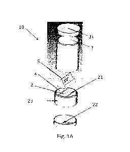
Fig. 1A is a schematic exploded view of at least part of a liquid target
system in
accordance with embodiments of the present invention.
Fig. 1B is a schematic vertical cross-section of at least part of the liquid
target
system of Fig. 1A that is in accordance with embodiments of the present
invention.
Fig. 2 is a a plot of the solubility, in grams of the salt per 100 mL of H20,
as
dependent on temperature, in degrees Celsius, for Ba(NO3)2 and Ra(NO3)2.
CA 03232148 2024- 3- 18
WO 2023/151859
PCT/EP2022/088084
Fig. 3 is a diagrammatic illustration of a liquid target system in accordance
with
embodiments of the present invention.
Fig. 4 is a schematic vertical cross-section a liquid target system in
accordance
with embodiments of the present invention.
5 Fig.
5 is a schematic vertical cross-section the liquid target system of Fig. 4,
after heating of the liquid target by irradiation of said liquid target.
In the different figures, the same reference signs refer to the same or
analogous
elements.
Description of illustrative embodiments
10 The
present invention will be described with respect to particular embodiments
and with reference to certain drawings but the invention is not limited
thereto but only
by the claims. The drawings described are only schematic and are non-limiting.
In the
drawings, the size of some of the elements may be exaggerated and not drawn on
scale
for illustrative purposes. The dimensions and the relative dimensions do not
correspond
to actual reductions to practice of the invention.
Furthermore, the terms first, second, third and the like in the description
and in
the claims, are used for distinguishing between similar elements and not
necessarily for
describing a sequence, either temporally, spatially, in ranking or in any
other manner.
It is to be understood that the terms so used are interchangeable under
appropriate
circumstances and that the embodiments of the invention described herein are
capable
of operation in other sequences than described or illustrated herein.
Moreover, the terms top, bottom, over, under and the like in the description
and
the claims are used for descriptive purposes and not necessarily for
describing relative
positions. It is to be understood that the terms so used are interchangeable
under
appropriate circumstances and that the embodiments of the invention described
herein
are capable of operation in other orientations than described or illustrated
herein.
It is to be noticed that the term "comprising", used in the claims, should not
be
interpreted as being restricted to the means listed thereafter; it does not
exclude other
elements or steps. It is thus to be interpreted as specifying the presence of
the stated
features, integers, steps or components as referred to, but does not preclude
the
presence or addition of one or more other features, integers, steps or
components, or
groups thereof. The term "comprising" therefore covers the situation where
only the
stated features are present and the situation where these features and one or
more
other features are present. The word "comprising" according to the invention
therefore
also includes as one embodiment that no further components are present. Thus,
the
CA 03232148 2024- 3- 18
WO 2023/151859
PCT/EP2022/088084
11
scope of the expression "a device comprising means A and B" should not be
interpreted
as being limited to devices consisting only of components A and B. It means
that with
respect to the present invention, the only relevant components of the device
are A and
B.
Similarly, it is to be noticed that the term "coupled" should not be
interpreted as
being restricted to direct connections only. The terms "coupled" and
"connected", along
with their derivatives, may be used. It should be understood that these terms
are not
intended as synonyms for each other. Thus, the scope of the expression "a
device A
coupled to a device B" should not be limited to devices or systems wherein an
output
of device A is directly connected to an input of device B. It means that there
exists a
path between an output of A and an input of B which may be a path including
other
devices or means. "Coupled" may mean that two or more elements are either in
direct
physical or electrical contact, or that two or more elements are not in direct
contact with
each other but yet still co-operate or interact with each other.
Reference throughout this specification to "one embodiment" or "an
embodiment" means that a particular feature, structure or characteristic
described in
connection with the embodiment is included in at least one embodiment of the
present
invention. Thus, appearances of the phrases "in one embodiment" or "in an
embodiment" in various places throughout this specification are not
necessarily all
referring to the same embodiment, but may. Furthermore, the particular
features,
structures or characteristics may be combined in any suitable manner, as would
be
apparent to one of ordinary skill in the art from this disclosure, in one or
more
embodiments.
Similarly it should be appreciated that in the description of exemplary
embodiments of the invention, various features of the invention are sometimes
grouped
together in a single embodiment, figure, or description thereof for the
purpose of
streamlining the disclosure and aiding in the understanding of one or more of
the
various inventive aspects. This method of disclosure, however, is not to be
interpreted
as reflecting an intention that the claimed invention requires more features
than are
expressly recited in each claim. Rather, as the following claims reflect,
inventive aspects
lie in less than all features of a single foregoing disclosed embodiment.
Thus, the claims
following the detailed description are hereby expressly incorporated into this
detailed
description, with each claim standing on its own as a separate embodiment of
this
invention.
Furthermore, while some embodiments described herein include some but not
other features included in other embodiments, combinations of features of
different
CA 03232148 2024- 3- 18
WO 2023/151859
PCT/EP2022/088084
12
embodiments are meant to be within the scope of the invention, and form
different
embodiments, as would be understood by those in the art. For example, in the
following
claims, any of the claimed embodiments can be used in any combination.
Furthermore, some of the embodiments are described herein as a method or
combination of elements of a method that can be implemented by a processor of
a
computer system or by other means of carrying out the function. Thus, a
processor with
the necessary instructions for carrying out such a method or element of a
method forms
a means for carrying out the method or element of a method. Furthermore, an
element
described herein of an apparatus embodiment is an example of a means for
carrying
out the function performed by the element for the purpose of carrying out the
invention.
In the description provided herein, numerous specific details are set forth.
However, it is understood that embodiments of the invention may be practiced
without
these specific details. In other instances, well-known methods, structures and
techniques have not been shown in detail in order not to obscure an
understanding of
this description.
The invention will now be described by a detailed description of several
embodiments of the invention. It is clear that other embodiments of the
invention can
be configured according to the knowledge of persons skilled in the art without
departing
from the technical teaching of the invention, the invention being limited only
by the terms
of the appended claims.
In a first aspect, the present invention relates to a liquid target system for
the
production of radio-isotopes. The liquid target system comprises a boiling
chamber for
containing the liquid and basic chemicals from which the radio-isotopes can be
produced using irradiation. The boiling chamber comprises an irradiation
window for
allowing the liquid and basic chemicals to be irradiated, causing the liquid
to evaporate
into vapor. The liquid target system is configured so that overheating of the
liquid target
is controlled by the thermodynamics of the evaporation/condensation process.
In a second aspect, the present invention relates to a method for producing
radio-isotopes. The method comprises irradiating a liquid target comprising
the liquid
and basic chemicals from which the radio-isotopes can be produced using
irradiation,
causing the liquid to evaporate into vapor. Herein, the thermodynamics of said
evaporation process are used so as to control overheating of the liquid
target.
In a third aspect, the present invention relates to a use of the liquid target
system
according to embodiments of the first aspect for producing radio-isotopes.
CA 03232148 2024- 3- 18
WO 2023/151859
PCT/EP2022/088084
13
Reference is made to Fig. 1A, which is a schematic exploded view of at least
part of a liquid target system 10 in accordance with embodiments of the
present
invention. Simultaneously, reference is made to Fig. 1 B, which is a schematic
vertical
cross-sectional view of said at least part of the liquid target system 10. In
this example,
the liquid target system, that is for the production of radio-isotopes,
comprises a boiling
chamber 2 for containing a liquid target 8, that consists of a liquid and
basic chemicals
from which radio-isotopes can be produced using irradiation. An irradiation
window 23,
that is in this example part of a wall of the boiling chamber 2, through which
said
irradiation may propagate, is comprised in a wall of the boiling chamber 2. In
this
example, the liquid comprised in the liquid target 8 in the boiling chamber 2
is water,
and the basic chemicals dissolved in the water is a salt comprising parent
nuclide Ra-
226, e.g., (Ra-226)(NO3)2, although the invention is not limited thereto. As
such, in this
example, the liquid target 8 consists of the liquid and the salt comprising Ra-
226.
The liquid target 8 is continuously irradiated by a high energy photon beam
through the irradiation window 23. As a result, the liquid target 8 will boil
under said
continuous irradiation, thereby transforming the liquid into vapor, i.e.,
water vapor (white
arrows). The water vapor is, subsequently, condensed in a condensation area 3
located
above the boiling chamber 2, thereby transforming the vapor into liquid
condensate. At
least the condensation area 3, but possibly also the condensate collection
area 4, and
possible also the boiling chamber 2, may be cooled by a water coolant fluid
bath and/or
a forced coolant fluid water circulation secondary system 32.
In this example, the liquid target system further comprises two condensate
collecting areas 4, different from the boiling chamber 2 and, in this example,
separated
from each other by separation walls 21. The two condensate collecting areas 4
are
located on opposite sides of the boiling chamber 2, each time separated by the
separation walls 21. The liquid target system is configured so that condensate
formed
in the condensation area 3 moves, e.g., drops, into the condensate collecting
areas 4
(arrows filled with horizontal stripes). This is, in this example, achieved as
walls of the
condensate collecting areas 4 are connected to walls of the condensation area
3, such
that liquid condensed on the walls of the condensation area 3 may move, e.g.,
downwards over said wall, into the condensate collecting areas 4. Furthermore,
in this
example, the liquid target system comprises a condensate steering element 5,
that
steers any condensate, away from the boiling chamber, to the condensate
collection
areas 4 (which may otherwise be called condensate collection chambers).
The condensate collecting areas 4 are fluidically coupled to the boiling
chamber
2, e.g., via openings 24 in the separation walls 21. For example, as in this
example, at
CA 03232148 2024- 3- 18
WO 2023/151859
PCT/EP2022/088084
14
least a portion of the separation walls 21 may be separated from a bottom of
the boiling
chamber 2 by a gap 24, through which the liquid may move between the
condensate
collecting areas 4 and the boiling chamber 2. Alternatively, e.g., tubing may
be used to
implement said fluidic coupling. Thereby, liquid condensate 41 collected in
the
condensate collecting areas 4 may flow into the boiling chamber 2 (black
arrows).
As such, the condensate collecting areas 4 and the boiling chamber 2 may be
considered as functioning as, in this example, three communicating vessels,
wherein
the liquid target 8 in the boiling chamber 2 is boiling, being directly
positioned in the
high energy photon beam, while the condensate is collected in the condensate
collecting areas 4, which is not boiling due to the lower energy deposition
into the
condensate collecting areas 4. Indeed, the condensate, i.e., liquid, in the
condensate
collecting areas 4 may not comprise Ra-226 in significant quantities for
absorbing the
irradiation, due to a continuous effective liquid flow (black arrows) from the
condensate
collecting areas 4, through the gap, to the boiling chamber 2, which
compensates a flow
of vapor (white arrows) and a flow of condensate (arrows with horizontal
stripes) via the
condensation area 3. In a steady state, the rates of each of these three flows
may be
substantially equal. The condensate 41 will be at a significantly lower
irradiation level.
Furthermore due to the absence of Ra, there is a lower heat absorption causing
the
condensate not to boil. In other words, as the condensate collecting areas 4
and the
boiling chamber 2 are essentially communicating vessels, the continuous loss
of water
mass in the boiling chamber 2 due to said boiling will be compensated by a
continuous
flow of water from the condensate collecting areas 4, through the hole at the
bottom of
the target, into the boiling chamber 2. The size of the gap (or, alternative,
a diameter of
the tubing) is preferably optimized in a way such that there is a continuous
flow of
condensate, i.e., liquid, towards the boiling chamber 2, so that substantially
no Ra-226
moves in the opposite direction, i.e., from the boiling chamber 2, towards and
into the
condensate collecting areas 4. The opening should therefore be not be too
narrow, and
not too large. Preferably, a liquid flow rate through the opening, towards the
boiling
chamber is from 0.1 cm/s to 20 cm/s, preferably from 0.5 cm/s to 5 cm/s, for
example,
1 cm/s. Preferably, said liquid flow rate substantially completely results
from the loss of
liquid in the boiling chamber 2 due to the boiling due to the irradiation, and
the gain of
liquid in the condensate collection area 4 due to the subsequent collection of
condensate therein. Due to the continuous flow back of condensate, i.e.,
liquid to the
liquid target in the boiling chamber 2, the liquid target may not boil to
dryness, and
overheating is prevented.
CA 03232148 2024- 3- 18
WO 2023/151859
PCT/EP2022/088084
In this example, the irradiation of the liquid target 8 results in the
production of
Ac-225, by the photonuclear reaction Ra-226 (y,n) Ra-225 (p-) Ac-225. It is
preferred
that any Ac-225 formed may be separated from the liquid target 8. In this
example, the
liquid target system comprises an opening 22 in a bottom of the boiling
chamber 2,
5 functioning as an inlet and/or outlet for the liquid target 8, e.g.,
before and after, but
preferentially not during, the irradiation. Thereby, the liquid target 8 may,
after
irradiation, be moved through the opening 22 to, e.g., a hot cell facility for
chemical
separation and purification of Ac-225. After said separation, the liquid
target may be
moved back through said opening 22 into the boiling chamber 2. To avoid
crystallization
10 and losses in any fluidic path, e.g., tubing, interconnecting the
boiling chamber 2 and
the hot cell facility, preferentially a certain rinsing volume of liquid, e.g.
diluted nitric acid,
is used directly after transferring the liquid target 8 through said fluidic
path. This may
further dilute the basic chemicals in the liquid target 8 and thus reduce
yields, that is,
by the excess volume introduced by the rinsing volume. Said excess volume may
be
15 removed by boiling, in the boiling chamber 2, the liquid target 8 while
establishing a flow
of an inert gas, e.g., helium or N2, from opening 22 to opening 31, thereby
removing
any excess vapor. However, by appropriate design of the target (ratio of the
volume of
the boiling chamber 2 to the volume of the condensate chambers 4), this excess
volume
may not be a problem. Indeed, the volume ratio between liquid in the boiling
room 2,
i.e., irradiated by the beam, and liquid in the condensate collection chambers
4 may be
optimized, and the concentration of Ra in the boiling chamber may be
increased. For
example, in the case of a 1/1 volume ratio, the concentration of Ra in the
beam may be
doubled in operation, i.e., during irradiation of the liquid target 8,
compared to a design
not comprising the condensate collection chambers 4. As a result, the
production yields
will also double. It is an advantage of this up-concentration that a low
amount of parent
nuclide, e.g., Ra-226, may be needed for the gamma production route to obtain
a high
isotope yield of Ra-225. This increased concentration may, during the
irradiation, not
be a problem with respect to a maximum in radium solubility, as the liquid
target may
be strongly heated, e.g., to 100 C that is the boiling temperature of water at
standard
pressure or even above 100 C when the pressure is above standard pressure,
such
that the solubility may be further increased.
In this example, the at least part of the liquid target system 10, i.e., the
boiling
chamber 2, the condensation area 3, and condensate collection areas 4, form a
cylindrical shape, so as to limit the amount of welds, and which increases the
strength
of this part of the liquid target system that may operate at elevated
pressures. Said
higher pressure may be used to increase the boiling point of the water, and
may
CA 03232148 2024- 3- 18
WO 2023/151859
PCT/EP2022/088084
16
influence the thermodynamics of the evaporation process. Indeed, when
operating this
liquid target 8 in the beam, any generated heat should be evacuated in a way
that
steady-state operation is safe and reliable. A boiling liquid target 8 is
preferred, as it is
an efficient and convenient way to remove the excess heat from a solution,
i.e., the
liquid target 8. Due to the relative small size of the liquid target 8,
pressurizing may be
strongly preferred to control the bubble size in the boiling liquid target 8.
The higher the
pressure, the smaller may be the bubbles and the better may be the boiling
performance. Pressure and steady-state temperature may be controlled for
optimizing
the thermohydraulic performance of the liquid target 8.
(Ra-226)(NO3)2 is well-suited for use in embodiments of the present invention,
as it has a relatively high solubility in water compared to other Ra-226
salts. The
compound is soluble for 13.9 g/ 100g water at 20 C and standard pressure (see
Erbacher, 0. Loslichkeits-Bestimmungen einiger Radiumsaltze; Berichte der
deutschen
chemischen Gesellschaft, 1930; Vol. 63: 141-156). However, also other
compounds,
e.g., (Ra-226)Cl2, may be used instead. Solubility of (Ra-226)(NO3)2 increases
significantly at higher temperatures. To approximate the solubility of (Ra-
226)(NO3)2 at
elevated temperatures, the solubility of barium nitrate can be taken as a good
approximation, due to very similar behaviour of alkaline earth metals Ra and
Ba or
Group 2 atoms (although the solubility of Ba(NO3)2 is slightly lower than that
of
Ra(NO3)2). Reference is made to Fig. 2, which is a plot of the solubility, in
grams of the
salt per 100 mL of H20, as dependent on temperature, in degrees Celsius. Data
are
shown for
Ba(NO3)2
(from http://periodic-table-of-elements.org/SOLUBILITY/barium_nitrate) that
are the
dark dots connected by the dotted curve, over a temperature range of from 0 C
to 100
C, and for Ra(NO3)2, for which we have only data at 20 C. It may be observed
that at
100 C, the solubility of Ba(NO3)2 increases by a factor of 3 compared to its
solubility at
20 C. As such, the solubility at 100 C is expected to be around 3 times
higher also for
Ra(NO3)2. We expect even higher solubility above 100 C. Indeed, the boiling
point of
water may be increased, firstly by the presence of the salt dissolved therein,
and
secondly by an increase in pressure.
A pressure dependence of Ra(NO3)2 may also be derived by comparing with
Ba(NO3)2. The water solubility of Ba(NO3)2 increases from 0.394 to 0.841
0.005 mol/kg
(from 13.79 to 29.435 0.175 g/100 g H20) when increasing the pressure from
standard
pressure up to 200MPa. (B.R. Churagulov, S.L. Lyubimov, A.N. Baranov, A.A.
Burukhin. Influence of Pressures up to 300 MPa on the Water Solubilities of
Poorly
Soluble Salts. September 1999. Russian Journal of Inorganic Chemistry
44(9):1489-
CA 03232148 2024- 3- 18
WO 2023/151859
PCT/EP2022/088084
17
1493). As such, it is not expected that elevated pressures in the boiling
chamber may
have a negative influence (decrease) on the solubility of Ra(NO3)2 in the
water of the
liquid target.
We now proceed with a quantitative example. VVith reference back to Fig. 1A
and Fig. 1B, as one example, we may consider a liquid target 8 having a volume
of 25
cm3, and it is not preferred to exceed solubility at room temperature, which
is 13.9 g/
100g water. Indeed, the liquid target 8 should be pumped in an out of the
boiling
chamber 2, i.e., between the boiling chamber 2 and the hot cell facility,
which is typically
approximately at room temperature. A higher concentration may, thus, result in
precipitation in the fluidic path connecting the boiling chamber 2 with the
hot cell facility.
As such, when at room temperature, the liquid target may only contain around 2
grams
of Ra-226. The goal is however to have 6 grams of the basic chemicals in the
boiling
chamber 2, to increase efficiency and yield of the liquid target system. As
such, instead,
a 6 gram Ra-226 target dissolved in 125 ml may be envisioned, and a volume
ratio
between liquid in the boiling chamber 2 and the condensate collection chambers
4 that
is equal to 1/4. As such, initially, 100 m L of the liquid target is present
in the condensate
collection chambers 4, and 25 mL is present in the boiling chamber 2. At the
start of the
irradiation, the Ra-226 is homogeneously divided among the compartments. When
the
boiling chamber 2 starts to boil under influence of said irradiation, due to
the mechanism
explained above, the Ra-226 from the condensate collection chambers 4 will
flow
towards the boiling chamber 2, and remain there during the course of the
irradiation. As
such, over the course of time, Ra-226 will become depleted in the condensate
collection
chambers 4, such that the condensate collection chambers 2 only comprise
liquid, i.e.,
condensate 41. Furthermore, the boiling chamber 2, comprising 25 cm3 of the
liquid
target, contains all remaining Ra-226 (i.e., 6 grams minus what has reacted to
form Ra-
225 or Ac-225). That is, effectively only the boiling chamber 2 comprises
liquid target 8.
As the water is heated, e.g., to 80 C or 100 C, the concentration of basic
chemicals in
the liquid target 8 is still below the solubility limit for Ra(NO3)2.
In addition to heating due to the irradiation, forced heating (not resulting
from
the irradiation) of the boiling chamber 2, until steady-state is achieved, may
be
performed. It is an advantage that a steady-state, therein thermodynamics are
continuous and predictable, may be rapidly achieved. Furthermore, when cooling
down
the liquid target 8 after said irradiation, slow cool-down may be preferred to
avoid any
precipitation of the Ra(NO3)2. One of the ways to achieve this could be to
submerge the
cylinder or target container, and then at least the boiling chamber 2 and
condensate
collection areas 4, in a water bath operating at, e.g., 70-80 C.
Alternatively, a purge
CA 03232148 2024- 3- 18
WO 2023/151859
PCT/EP2022/088084
18
gas, causing forced mixing, may be introduced, e.g., through opening 22 and
leaving
through further opening 31 located above the boiling chamber 2.
Reference is made to Fig. 3, which is a schematic view of a liquid target
system
1 in accordance with embodiments of the present invention, which may comprise
the at
least part of the liquid target system 10 of Fig. 1A and Fig. 1B. The boiling
chamber
comprised in the at least part of the liquid target system 10 may be
irradiated by an
irradiation beam 26 originating from an irradiation beam generator 25. In this
example,
an opening 22 in a bottom of the boiling chamber may be coupled to a buffer
vessel 6
via valve V3. Said buffer vessel 6 is coupled, via valve V8, to a hot cell
facility 61. Said
buffer vessel 6 is further connected, via valve V5, to an inlet for
introducing
demineralized water 62. Said inlet for introducing demineralized water 62 is
further
connected, via valve V7, to the further opening 31. In this example,
compressed gas,
e.g., N2 or He, may be introduced, from a compressed gas source 63, e.g., a
compressed gas cylinder, through the opening 22, via valve V4, buffer vessel
6, and
valve V3, or through the further opening 31, through valve V2. Furthermore, a
vacuum
may be introduced, from a vacuum source 64, e.g., a pump, through the opening
22,
via valve V6, buffer vessel 6 and valve V3, or alternatively through the
further opening
31, through valves V6, V4, and V2. The further opening 31 may be coupled to a
chimney
7, via a volume comprising active coal 71 or any other system for capturing
radioactive
non-condensable gasses.
In an initial state, all valves V1-8 are closed. The buffer vessel 6 may be,
subsequently, filled with liquid target by opening valves V6 and V8, such that
a vacuum
pulls the liquid target from the hot cell facility 61.
Subsequently, the liquid target may be moved to the boiling chamber and the
condensate collecting areas by opening valves V4, V3 and V1, for introducing a
gas
flow (e.g., He or N2) through the buffer vessel 6 via the boiling chamber in
the at least
part of the liquid target system 10, then through the active coal 71, and to
the chimney
7, thereby moving the liquid target from the buffer vessel 6 to the boiling
chamber. The
fluid connection connecting the boiling chamber with the buffer vessel 6 may
be flushed
with demineralized water from the inlet for introducing demineralized water
62, by first
filling the buffer vessel 6 with demineralized water by only having valve V5
opened, then
close V5, open valve V4, and open valve V3. Alternatively, flushing may be
performed
by opening valve V7. This may result in additional liquid in the boiling
chamber, but in
the present invention, this may not be a problem due to potential up-
concentration of
the basic chemicals in the boiling chamber. Furthermore, in the next step,
excess liquid
in the boiling chamber may be evaporated and removed from the boiling chamber
by a
CA 03232148 2024- 3- 18
WO 2023/151859
PCT/EP2022/088084
19
gas flow from the compressed gas source 63, through the boiling chamber, to
the
chimney 7, thereby reducing the volume of liquid in the boiling chamber.
In the next step, valve V1 is opened, and the liquid target in the boiling
chamber
is boiled by using a low power irradiation beam 26 originating from the
irradiation beam
generator 25. Then irradiating, no valves, or, alternatively, possible only
valves V4 and
V3 may be opened, and V1 slightly opened, so as to introduce compressed gas
(e.g.,
Ar, He or N2) in the at least part of the liquid target system 10, and so as
to obtain a
preferred, e.g., high, pressure in the at least part of the liquid target
system 10. The flow
may be controlled via flow controller 631 and pressure regulator 632. The
increased
pressure in the boiling chamber may enable the liquid in the boiling chamber
to be at
an increased temperature compared to atmospheric pressures, which may improve
solubility of the basic chemicals. Furthermore, for example when the basic
chemicals
comprise Ra-226, a small gas flow may be retained so as to remove and collect
any
gases, e.g., Rn, formed in the boiling chamber. It is an advantage of
embodiments of
the present invention that the liquid target system is compatible with Rn
collection.
After the photonuclear reaction in the boiling chamber, any radio-isotopes
formed in the boiling chamber may be collected. For this, all valves may be
closed, then
valves V2 and V3 may be opened, to move, by a gas flow, the liquid target,
comprising
the radio-isotopes, from the boiling chamber to the buffer vessel 6. Possibly,
afterwards,
the tubing connecting the boiling chamber to the buffer vessel 6 may be
flushed with
demineralized water by opening valve V7. Finally, the buffer vessel 6 may be
emptied
to the hot cell facility 61, by closing all valves, then opening valves V8 and
V4, followed
by shortly opening valve V5 for flushing with demineralized water.
Although the at least part of the liquid target system 10 in the above
explanation
has been assumed to be the embodiment of the example relating to Fig. 1A and
Fig.
1B, the at least part of the liquid target system 10 may instead be the
embodiments of
the subsequent example, or comprise features of both examples.
Reference is made to Fig. 4, which is a schematic representation of a further
example of a liquid target system in accordance with embodiments of the
present
invention. The boiling chamber 2 comprises a liquid target 8, comprising the
liquid and
basic chemicals from which radio-isotopes can be produced. Irradiation 26
incident on
the liquid target 8 results in heating of the liquid target 8, such that the
liquid is
evaporated to form vapor in a volume 9 above the boiling chamber 2. Walls of
said
volume thermally insulated by insulation material 91, so that a high
temperature of the
vapor in said volume may be achieved. Thereby, a higher concentration of the
vapor in
the volume may achieved, enabling pressure to build up. In other words, the
volume 9
CA 03232148 2024- 3- 18
WO 2023/151859
PCT/EP2022/088084
may comprise a large amount of the liquid in the vapor phase, i.e., the vapor.
In
embodiments, a ratio between a volume of the gas vapor in the volume 9 and a
volume
of the liquid target 8 in the boiling chamber 9 is at least 2, preferably at
least 5.
In other words, aside from directly condensing the vapor that is formed,
5
alternatively the volume above the boiling chamber thus can be used for
storing the
evaporated solvent as vapor.
Reference is made to Fig. 5. As a result of the evaporation due to the
irradiation,
and the large amount of vapor that is formed, the volume of the liquid target
8 is
reduced. Thereby, the concentration of the basic chemicals therein is
increased, which
10 may
increase the efficiency and yield of the nuclear reaction, e.g., a
photonuclear
reaction, of the basic chemicals to form the radio-isotopes. In embodiments,
the
irradiation is adapted for producing a pressure in the volume 9 that is up to
20 bar, e.g.
up to 10 bar. The upper limit of the pressure is typically limited by the
pressure that the
walls of the liquid target system may withstand. The high pressure that is
used may
15
improve solubility of the basic chemicals in the liquid target 8 as it
increases the boiling
temperature, enabling, in turn, more liquid to evaporate without resulting in
precipitation
of the basic chemicals from the liquid target 8. During the irradiation of the
liquid target
8, the concentration of basic chemicals in the liquid is preferably higher
than a solubility
of the basic chemicals in the liquid at room temperature, e.g., in absence of
the
20
irradiation. In this example, a high irradiation may thus result in a high
yield both
because of said high irradiation, and the up-concentration of basic chemicals
in the
liquid target 8. Overheating may, furthermore, be prevented by finding a
balance
between irradiation power and power loss due to evaporation of the liquid from
the liquid
target 8.
It is to be noted that in embodiments of the present invention, the operating
conditions as well as additional measures can be selected so as to limit or
prevent
radiolysis, or reverse it by re-combination of oxygen with hydrogen. Such
measures are
known in the art. On example of a technical solution is given by
https://link.springercom/article/10.1007/BF02387473.
It is to be understood that although preferred embodiments, specific
constructions and configurations, as well as materials, have been discussed
herein for
devices according to the present invention, various changes or modifications
in form
and detail may be made without departing from the scope of this invention.
Steps may
be added or deleted to methods described within the scope of the present
invention.
CA 03232148 2024- 3- 18