Note : Les descriptions sont présentées dans la langue officielle dans laquelle elles ont été soumises.
WO 2023/064286
PCT/US2022/046297
TITLE OF APPLICATION
Utilizing a Seat Assembly Having a Set of Limit Straps to Limit Deflection
BACKGROUND
The U.S. Department of Transportation has set forth Federal Motor Vehicle
Safety
Standards (FMVSS). For example, FMVSS 207 relates to seating systems, the
contents
and teachings of which are hereby incorporated by reference in their entirety.
As another
example, FMVSS 210 relates to seat belt assembly anchorages, the contents and
teachings of which are hereby incorporated by reference in their entirety.
In compliance with such standards, a conventional vehicle may be equipped with
a columnar seat mount having an upper post mounted to the vehicle's ceiling
and a lower
leg mounted to the vehicle's floor. The lower leg slides into the bottom of
the upper post
to reduce movement.
SUMMARY
Unfortunately, there are deficiencies to the above-described conventional
vehicle.
For example, although the columnar seat mount may comply with Federal
Regulations,
the columnar seat mount is made of relatively heavy steel material which
increases the
weight of the vehicle thus imposing significant demands on features such as
the vehicle's
suspension, fuel efficiency, serviceability, and so on.
Moreover, under certain potentially high deformation situations, it may be
possible for the columnar seat mount to sustain significant damage. For
example, in the
context of a conventional vehicle, a collision may cause shearing of one or
more of the
steel parts of the columnar seat mount due to forward momentum. As another
example,
in the context of an armored vehicle, a blast may cause severe deformation or
rupture of
the steel parts of the columnar seat mount due to the uneven direction of the
momentum.
In contrast to the above-described conventional vehicle, improved techniques
are
directed to utilizing a seat assembly having a set of limit straps to limit
deflection in the
direction of the collision. Along these lines, such a seat assembly may
include a seat
1
CA 03234988 2024-4- 12
WO 2023/064286
PCT/US2022/046297
support that supports a vehicle seat from a vehicle ceiling and a base that
forms a slip
joint with the seat support from a vehicle floor. In such a situation, the set
of limit straps
limits deflection of the slip joint in response to a change in momentum caused
by an
abrupt halt or collision. In the event of a blast, the set of limit straps may
limit excessive
overall deflection of the columnar seat mount while allowing some movement
therefore
reducing stress in seat mount material and likelihood of a rupture or failure.
In some
arrangements, at least a portion of the seat assembly may be formed of light-
weight
metallic material such as aluminum which provides more compliance than steel
to reduce
the likelihood of shearing and is lighter in weight than steel thus lowering
the weight of
the vehicle.
One embodiment is directed to a vehicle which includes a vehicle ceiling, a
vehicle floor, and a vehicle seat assembly that couples with the vehicle
ceiling and the
vehicle floor. The vehicle seat assembly includes a seat support that supports
a vehicle
seat from the vehicle ceiling, a base that forms a slip joint with the seat
support from the
vehicle floor, and a set of limit straps constructed and arranged to limit
deflection of the
slip joint in response to deformation between the vehicle ceiling and the
vehicle floor
(e.g., a vehicle collision, deformation between the vehicle ceiling and the
vehicle floor
possibly due to a blast, etc.). Each limit strap of the set of limit straps
has a first end that
attaches to a portion of the slip joint and a second end that attaches to the
vehicle floor.
It should be understood that the vehicle ceiling and the vehicle floor may
form at
least a portion of a vehicle cabin. Accordingly, the vehicle may be configured
for a
variety of different environments, applications, functions, etc. Suitable
arrangements
include reconnaissance vehicles, armored vehicles, commercial vehicles, and
the like.
In some arrangements, the vehicle includes an armored vehicle suspension
coupled with an armored vehicle cabin. The armored vehicle suspension is
constructed
and arranged to maneuver the vehicle within a blast-prone environment.
Another embodiment is directed to a vehicle seat assembly which includes:
(A) a seat support constructed and arranged to support a vehicle seat
from a
vehicle ceiling,
2
CA 03234988 2024-4- 12
WO 2023/064286
PCT/US2022/046297
(B) a base constructed and arranged to form a slip joint with the seat
support
from a vehicle floor, and
(C) a set of limit straps constructed and arranged to limit deflection of
the slip
joint in response to a large force that may cause deformation between the
vehicle ceiling and the vehicle floor.
Each limit strap of the set of limit straps has a first end constructed and
arranged to attach
to a portion of the slip joint and a second end constructed and arranged to
attach to the
vehicle floor.
In some arrangements, the seat support includes a midsection that attaches to
the
vehicle seat, an upper end constructed and arranged to connect with the
vehicle ceiling,
and a lower end constructed and arranged to reside above the vehicle floor
when the seat
support forms the slip joint with the base.
In some arrangements, the set of limit straps includes a first limit strap
having a
first end that attaches to the seat support and a second end that attaches to
the vehicle
floor.
In some arrangements, the set of limit straps further includes a second limit
strap
having a first end that attaches to the seat support and a second end that
attaches to the
vehicle floor. The first and second limit straps are disposed parallel to each
other.
In some arrangements, each limit strap of the set of limit straps includes a
belt
formed of nylon webbing, a first metallic anchor plate disposed at the first
end to fasten to
the lower end of the seat support, and a second metallic anchor plate disposed
at the
second end to fasten to the vehicle floor.
In some arrangements, the vehicle seat assembly further includes a first set
of
bolts that attaches the first metallic anchor plate of each limit strap of the
set of limit
straps to the lower end of the seat support and a second set of bolts that
attaches the
second metallic anchor plate of each limit strap of the set of limit straps to
the vehicle
floor. It should be understood that such bolts enable easy serviceability such
as strap
installation, replacement, removal, and so on. Furthermore, the use of
multiple limit
straps that attach using multiple anchor plates enables loads/stresses to be
distributed
3
CA 03234988 2024-4- 12
WO 2023/064286
PCT/US2022/046297
across the bolts rather than at single points thus improving bolt performance
and
reliability.
In some arrangements, at least a portion of the seat support and the base are
formed of aluminum or similar light weight material. Such material does not
compromise blast mitigation (e.g., in the context of an armored vehicle).
In some arrangements, the seat support and the base have rectangular
cross-sections. Such arrangements provide certain advantages such as strength,
manufacturability, etc.
Other embodiments are directed to apparatus, devices, and related componentry.
Some embodiments are directed to various vehicles, systems, sub-systems,
manufacturing
processes, installation processes, methods regarding use, serviceability, and
so on, which
utilize a seat assembly having a set of limit straps to limit deflection.
This Summary is provided merely for purposes of summarizing some example
embodiments so as to provide a basic understanding of some aspects of the
disclosure.
Accordingly, it will be appreciated that the above described example
embodiments are
merely examples and should not be construed to narrow the scope or spirit of
the
disclosure in any way. Other embodiments, aspects, and advantages will become
apparent from the following detailed description taken in conjunction with the
accompanying drawings which illustrate, by way of example, the principles of
the
described embodiments.
BRIEF DESCRIPTION OF THE DRAWINGS
The foregoing and other objects, features and advantages will be apparent from
the following description of particular embodiments of the present disclosure,
as
illustrated in the accompanying drawings in which like reference characters
refer to the
same parts throughout the different views. The drawings are not necessarily to
scale,
emphasis instead being placed upon illustrating the principles of various
embodiments of
the present disclosure.
4
CA 03234988 2024-4- 12
WO 2023/064286
PCT/US2022/046297
Fig. 1 is a perspective view of an example vehicle which utilizes a seat
assembly
having a set of limit straps to limit deflection in accordance with certain
embodiments.
Fig. 2 is a side view of an interior portion of a vehicle which utilizes a
seat
assembly having a set of limit straps to limit deflection in accordance with
certain
embodiments.
Fig. 3 is a perspective view of a portion of a seat assembly in accordance
with
certain embodiments.
Fig. 4 is a front view of the seat assembly in accordance with certain
embodiments.
Fig. 5 is yet another view of the seat assembly in accordance with certain
embodiments.
Fig. 6 is a rear (or reverse) view of the seat assembly in accordance with
certain
embodiments.
Fig. 7A is a side view of the seat assembly in accordance with certain
embodiments.
Fig. 7B is a detailed side view of a portion of the seat assembly in
accordance
with certain embodiments.
Fig. 8A is a reverse perspective view of the seat assembly in accordance with
certain embodiments.
Fig 8B is a detailed reverse perspective view of a portion of the seat
assembly in
accordance with certain embodiments.
Fig. 9A is a reverse view of the seat assembly in accordance with certain
embodiments.
Fig. 9B is a detailed reverse view of a portion of the seat assembly in
accordance
with certain embodiments.
DETAILED DESCRIPTION
An improved technique is directed to utilizing a seat assembly having a set of
limit straps to limit deflection. Along these lines, such a seat assembly may
include a seat
5
CA 03234988 2024-4- 12
WO 2023/064286
PCT/US2022/046297
support that supports a vehicle seat from a vehicle ceiling and a base that
forms a slip
joint with the seat support from a vehicle floor. In such a situation, the set
of limit straps
limits deflection of the slip joint in response to a large force that may
cause deformation
between the vehicle ceiling and the vehicle floor. In some arrangements, at
least a
portion of the seat assembly may be formed of light-weight metallic material
such as
aluminum which provides more compliance than steel to reduce the likelihood of
shearing and is lighter in weight than steel thus lowering the weight of the
vehicle.
The various individual features of the particular arrangements,
configurations, and
embodiments disclosed herein can be combined in any desired manner that makes
technological sense. Additionally, such features are hereby combined in this
manner to
form all possible combinations, variants and permutations except to the extent
that such
combinations, variants and/or permutations have been expressly excluded or are
impractical. Support for such combinations, variants and permutations is
considered to
exist in this document.
FIG. 1 shows an example vehicle 100 residing within an environment 110 in
accordance with certain embodiments. The vehicle 100 includes, among other
things, a
vehicle seat assembly 120 which utilizes a set of limit straps to limit
deflection. The
vehicle 100 may further include various vehicle equipment 130 (e.g., a
suspension/frame/body, a propulsion system, a vehicle cabin, specialized
componentry,
etc) and non-vehicle equipment 140 (es , cargo, add-ons, sensing devices,
communications systems, etc.).
During operation, the vehicle 100 may undergo certain stresses due to one or
more
environmental factors. Along these lines, the vehicle 100 may be called upon
to
maneuver within extreme environmental conditions, to ride over rough terrain,
to operate
within in a war zone, and so on.
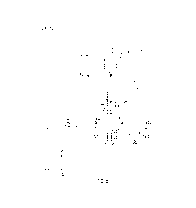
FIG. 2 shows a side view of an interior portion 200 of the vehicle 100 which
includes the vehicle seat assembly 120 in accordance with certain embodiments.
The seat
assembly 120 includes a seat support 210 constructed and arranged to support a
vehicle
seat 212 from a vehicle ceiling 214. The seat assembly 120 further includes a
base 220
6
CA 03234988 2024-4- 12
WO 2023/064286
PCT/US2022/046297
constructed and arranged to form a slip joint 222 with the seat support 210
from a vehicle
floor 224. The seat assembly 120 further includes a set of limit straps 230
(i.e., one or
more limit straps 230) constructed and arranged to limit deflection of the
slip joint 222 in
response to deformation between the vehicle ceiling 214 and the vehicle floor
224.
In some arrangements, the vehicle ceiling 214 and the vehicle floor 224 form
at
least a portion of an armored vehicle cabin. In such arrangements, the vehicle
100
(FIG. 1) may be equipped with an armored vehicle suspension, coupled with the
armored
vehicle cabin, to enable the vehicle 100 to maneuver effectively within a
blast-prone
environment (over off-road terrain, while encountering blasts and/or under
attack, and so
on).
As shown in FIG. 2, the seat support 210 includes a midsection 240 that
attaches
to the vehicle seat 212, an upper end 242 that connects with the vehicle
ceiling 214, and a
lower end 244 that resides above the vehicle floor 224 when the seat support
210 forms
the slip joint 222 with the base 220.
As further shown in FIG. 2, each limit strap 230 of the set of limit straps
has a
first end 252(1) that attaches to a portion of the slip joint 222 and a second
end 252(2)
that attaches to the vehicle floor 224. As will be described in further detail
shortly, the
first ends 252(1) fasten to the lower end 244 (e.g., a bottom portion) of the
seat support
210.
During operation, it is possible for the seat support 210 and the base 220 to
move
relative to each other. For example, the vehicle ceiling 214 and the vehicle
floor 224 may
move relative to each other along the Y-axis causing the slip joint 222 to
actuate or
translate. During such translation, the seat portion 210 slides over the base
220 while
supporting and maintaining proper positioning of the seat 212.
In some situations, the vehicle ceiling 214 and the vehicle floor 224 may move
in
a different or awkward manner such as side to side, in a torqueing or twisting
manner,
combinations thereof, and so on. In such situations, the set of limit straps
230 prevents
the slip joint 222 from over-deflecting. For example, although the bottom
portion 240 of
the seat portion 210 may be urged in the positive Z-direction, the set of
limit straps 230
7
CA 03234988 2024-4- 12
WO 2023/064286
PCT/US2022/046297
limits the range of motion of the bottom portion 240 thus preventing the slip
joint 222
from extending too far in the Z-direction. In accordance with certain
embodiments, the
set of limit straps 230 limits the lower end 244 of the seat support 210 to a
predefined
displacement threshold in the Z-direction (e.g., an inch, two inches, four
inches, six
inches, etc.). Accordingly, the seat assembly 120 is able to withstand such
movement and
avoid damage.
FIGS. 3 through 9B show further details. Along these lines, FIG. 3 provides a
detailed view 300 of a portion of the seat assembly 120. In accordance with
certain
embodiments, there are multiple limit straps 230, e.g., two limit straps 230
which are
parallel to each other as shown in FIGS. 8B and 9B.
Each limit strap 230 of the set of limit straps (e.g., see FIG. 3) includes a
belt 310,
a first metallic anchor plate 312(1) that fastens to the lower end 240 of the
seat support
210, and a second metallic anchor plate 312(2) that fastens to an anchor 320
on the
vehicle floor 224 (FIG. 2).
In accordance with certain embodiments, the belts 310 are formed of a material
that provides compliance, pull strength, and resiliency. Suitable material
includes mil
spec nylon webbing, other forms of seat belt material, and/or other fabric-
like substances
that provide similar properties.
In some arrangements, the anchor plates 312 fasten using hardware. In
accordance with certain embodiments, a single bolt 330 attaches multiple
anchor plates
312 of multiple limit straps 230. Accordingly, stresses/loading on the bolt
330 and
through the limit straps 230 are more effectively distributed throughout thus
avoiding
failure at a single point.
In some arrangements, the slip joint 222 may be provisioned with a bushing 340
that separates the ends of the seat support 210 and the base 220. Such a
bushing 340
permits further compliance between the seat support 210 and the base 220.
In accordance with certain embodiments, the seat assembly 120 is shown as
supporting a seat for a single user. However, this is by way of example only
and in other
embodiments, the seat assembly 120 supports a seat configured for multiple
users.
8
CA 03234988 2024-4- 12
WO 2023/064286
PCT/US2022/046297
A front view of an example seat is provided in FIG. 5. A reverse view of the
example seat is provided in FIG. 6. It should be appreciated that the set of
limit straps
230 limit over-deflection of the seat assembly 120 in the forward direction.
This forward
direction is the positive Z-direction in FIG. 2.
A similar set of limit straps 230 may be employed to limit over-deflection of
the
seat assembly 120 in other directions such as the rear direction, the side
directions, and so
on. In another embodiment, another set of limit straps 230 restrains the seat
assembly
120 from deflecting too far in the negative Z-direction in FIG. 2. In yet
another
embodiment, other sets of limit straps 230 may restrain the seat assembly 120
from
deflecting too far along in different directions along the X-axis in FIG. 2,
and so on. It
should be appreciated that the limit straps 230 may be employed to limit
deflecting in a
single direction or multiple directions in accordance with certain
embodiments.
Other views of the example seat are provided in FIG. 7A, FIG. 8A, and FIG. 9A
to illustrated the context of further connection details shown in FIG. 7B,
FIG. 8B, and
FIG. 9B, respectively. Also shown in these figures are views of a foot rest
710 which is
angled (or inclined) in an upward, rear-to-front direction. Such a foot rest
may be used by
one or more passengers other than the passenger sitting on the seat assembly
120 (e.g., a
passenger sitting in another seat assembly 120 immediately behind that shown
in FIG.
7A, FIG. 8A, and FIG. 9A).
As described above, improved techniques are directed to utilizing a seat
assembly
120 having a set of limit straps 230 to limit deflection. Along these lines,
such a seat
assembly 120 may include a seat support 210 that supports a vehicle seat 212
from a
vehicle ceiling 214 and abase 220 that forms a slip joint 222 with the seat
support 210
from a vehicle floor 224. In such a situation, the set of limit straps 230
limits deflection
of the slip joint 222 in response to a change in momentum caused by an abrupt
halt, a
collision, etc. In the event of a blast, the set of limit straps 230 may limit
excessive
overall deflection of the columnar seat mount while allowing some movement
therefore
reducing stress in seat mount material and likelihood of a rupture or failure.
In some
arrangements, at least a portion of the seat assembly 120 may be formed of
light-weight
9
CA 03234988 2024-4- 12
WO 2023/064286
PCT/US2022/046297
metallic material such as aluminum which provides more compliance than steel
to reduce
the likelihood of shearing and is lighter in weight than steel thus lowering
the weight of
the vehicle 100.
It should be understood that other sets of limit straps 230 may be employed to
limit deflection of the seat assembly 120 in various other directions such as
the negative
Z-direction, the positive X-direction, the negative X-direction, combinations
thereof, etc.
Moreover, such limit straps 230 may be angled more steeply from the vehicle
floor 224 to
limit deflection along the Y-axis in accordance with certain embodiments.
Furthermore, in accordance with certain embodiments, one or more limit straps
230 may attach to a portion of the vehicle 100 other than the vehicle floor
224. For
example, in accordance with certain embodiments, the end of one or more limit
strap 230
attaches to a wall, the vehicle ceiling 214, a beam or other structure
accessible within the
vehicle cabin, combinations thereof, and so on.
As shown in the figures, there are two limit straps extending in a side-by-
side
configuration in accordance with certain embodiments. As a result, the loading
on the
attaching hardware is distributed, e.g., each limit strap applies loading to a
different
portion of the attaching bolt. In some embodiments, the number of limit straps
230 in
each set of limit straps 230 is a number different than two, such as one,
three, four, etc.
In some embodiments, the number of limit straps 230 in different sets of limit
straps 230
is different to accommodate different scenarios (e g , different deflection
limits, different
deflection directions, etc.).
Additionally, it should be understood that the portions of the seat assembly
120,
which are mounted to the various other portions of the vehicle 100, may be
robustly and
reliably attached. Techniques for attaching these portions of the set assembly
120 to the
portions of the vehicle 100 include bolts, anchors, welds, combinations
thereof, etc.
Furthermore, the attachment points may be plating (e.g., a floor plate), a
beam, a support
member, trusswork, combinations thereof, and so on.
It should be appreciated that, conventionally, a company may design a seat
post or
mount that can withstand the FMVSS pull test for compliance by hard mounting
the post
CA 03234988 2024-4- 12
WO 2023/064286
PCT/US2022/046297
to other parts of the vehicle. This can have the downsides of increased weight
or in the
case of an armored vehicle, negative blast mitigation performance.
It should be appreciated that certain improvements disclosed herein can be
utilized to drastically reduce weight from the seat post structure or
alternate material
options without compromising compliance to certain standards. In the case of
armored
vehicles, this use case also has the benefit of not adding any consequences to
blast
mitigation steps that a hard mounted seat post may have. Such improvements may
be
employed in both military and commercial automotive vehicles.
Moreover, the various improvements disclosed herein may be implemented in
craft other than land vehicles In accordance with certain embodiments, the
improvements are deployed in non-land vehicles such as aircraft, watercraft,
amphibious
vehicles, combinations thereof, and so on.
In accordance with certain embodiments, there are one or more of the following
differentiators:
Ultra-Lightweight
- Universally Applicable
- No added negative effects to blast mitigation in armored vehicles
- Utilization of automotive limit straps which use mil-spec nylon webbing
The various individual features of the particular arrangements,
configurations, and
embodiments disclosed herein can be combined in any desired manner that makes
technological sense. Additionally, such features are hereby combined in this
manner to
form all possible combinations, variants and permutations except to the extent
that such
combinations, variants and/or permutations have been expressly excluded or are
impractical. Support for such combinations, variants and permutations is
considered to
exist in this document
11
CA 03234988 2024-4- 12