Note : Les descriptions sont présentées dans la langue officielle dans laquelle elles ont été soumises.
CA 03235285 2024-04-11
WO 2023/075841 PCT/US2022/026468
REAR-FACING POULTRY CLAW SYSTEM AND METHOD
RELATED APPLICATION
This application claims the benefit under 35 U.S.C. 119 of U.S. Provisional
Application Serial No. 63/273,423, filed 29 October 2021, and titled REAR-
FACING
POULTRY CLAW SYSTEM AND METHOD, which is incorporated herein by reference
in its entirety.
FIELD
Rear-facing poultry claw systems and methods are described herein.
BACKGROUND
Precise positioning of poultry toes and claws is difficult due to the size and
activity
levels of birds. In some instances, birds are handled manually, i.e.,
individuals must
physically hold the bird to position its toes and claws in selected locations
and/or
orientations. Manual handling of birds to position their toes and claws is, in
addition to
being difficult, also potentially dangerous to the bird.
Although carriers and other restraints designed to hold birds are known, the
focus
has largely been on precise positioning of beaks and bills. U.S. Patent No.
5,651,731
(Gorans et al.) describes devices designed to restrain the heads of birds with
the remainder
of the bird being either manually restrained or unrestrained.
U.S. Patent No. 9,808,328 (Gorans et al.) describes carriers designed to
restrain the
heads and torsos of birds, as well as their legs above the hock joint with no
restraint on the
shanks of the birds. U.S. Patent No. 9,901,432 (Erickson et al.) discloses a
system and
method for processing the rear claw (sometimes referred to as the hind claw or
anatomically identified as "phalange I") of birds restrained in, e.g., the
carriers of U.S.
Patent No. 9,808,328.
1
CA 03235285 2024-04-11
WO 2023/075841 PCT/US2022/026468
SUMMARY
Rear-facing poultry claw systems and methods are described herein. In one or
more
embodiments, the systems and methods may be used to position and/or detect the
claw of
the rear-facing toe on one or both shanks of birds.
The rear-facing poultry claw systems and methods may allow for accurate
detection
of the claws on one or both of the rear-facing toes of poultry (such as, e.g.,
ducks,
chickens, geese, and turkeys) where the rear-facing toes are those anatomical
digits found
on the shanks of birds above/proximal/superior to the distal ends of the
shanks. Each shank
of a bird contains the metatarsus and extends from the hock joint (sometimes
referred to as
.. the ankle joint) to the joints between the distal phalanges (sometimes
referred to as the
toes). The rear-facing toes on the shanks are located proximal from the distal
phalanges,
are commonly referred to anatomically as "phalange I" and generally face in
the rearward
(dorsal) direction. The rear-facing toe on each shank can be distinguished
from the distal
phalanges which are commonly referred to anatomically as "phalanges II, III,
and IV" and
extend from the distal end of the shank in a forward-facing (ventral)
direction.
In one or more embodiments, the rear-facing poultry claw systems and methods
may allow for simultaneous positioning of the rear-facing toes on both shanks
of a bird to,
for example, expedite any inspections, processing, etc. of the claws on the
rear-facing toes.
In one or more embodiments, the rear-facing poultry claw systems and methods
involve moving the forward-facing toes on one or both shanks in a direction
towards the
torso or head of the bird while restraining the shanks. Such manipulation of
the forward-
facing toes on a shank typically causes the rear-facing toe to extend away for
the shank,
thus making detection of the claw on the rear-facing toe easier and more
consistent.
Extension of the rear-facing toe also typically makes any inspection,
processing, etc. of the
claw on the rear-facing toe easier and more consistent.
In one or more embodiments, the rear-facing poultry claw systems include claw
sensors that are used to deliver energy to rear-facing claws to process the
rear-facing claws
to retard their growth.
2
CA 03235285 2024-04-11
WO 2023/075841 PCT/US2022/026468
In a first aspect, one or more embodiments of a rear-facing poultry claw
system as
described herein include: a seat lift operably attached to a system frame, the
seat lift
configured to move between a ready position and a lift position; a toe control
bar operably
attached to the system frame, the toe control bar configured to move between a
retracted
.. position and a control position; a claw sensor configured to detect a claw
of a rear-facing
toe on a shank of a bird; a sensor track operably attached to the system
frame, the sensor
track defining a sensing axis, wherein the claw sensor is mounted on the
sensor track and
configured to move along the sensing axis between a home position and a
forward
position, wherein the claw sensor is closer to the toe control bar in the
forward position
than the home position; a seat lift actuator operably connected to the seat
lift, the seat lift
actuator configured to rotate the seat lift about the lift axis to move the
seat lift between the
ready position and the lift position; a control bar actuator operably
connected to the toe
control bar, the control bar actuator configured to move the toe control bar
between the
retracted position and the control position; a claw sensor actuator operably
connected to
the claw sensor, the claw sensor actuator configured to move the claw sensor
along the
sensing axis between the home position and the forward position; and a
controller operably
connected to the seat lift actuator, the control bar actuator, and the claw
sensor actuator,
wherein the controller is configured to: operate the seat lift actuator such
that the seat lift
actuator moves the seat lift from the ready position to the lift position,
operate the control
bar actuator such that the control bar actuator moves the toe control bar from
the retracted
position to the control position after operating the seat lift actuator to
rotate the seat lift
from the ready position to the lift position, and operate the claw sensor
actuator such that
the claw sensor actuator moves the claw sensor along the sensing axis from the
home
position to the forward position after operating the control bar actuator to
move the toe
control bar from the retracted position to the control position.
In one or more embodiments of rear-facing poultry claw systems described
herein
according to the first aspect, the seat lift is configured to rotate about a
lift axis when
moving between the ready position and the lift position.
3
CA 03235285 2024-04-11
WO 2023/075841 PCT/US2022/026468
In one or more embodiments of rear-facing poultry claw systems described
herein
according to the first aspect, the toe control bar is configured to rotate
about a control bar
axis when moving between the retracted position and the control position.
In one or more embodiments of rear-facing poultry claw systems described
herein
according to the first aspect, the system further comprises a track actuator
operably
attached to the sensor track, wherein the track actuator is configured to move
the sensor
track between a base position and a sensing position, and wherein the
controller is operably
connected to the track actuator, the controller being configured to operate
the track actuator
such that the track actuator moves the sensor track from the base position to
the sensing
position after operating the control bar actuator to move the toe control bar
from the
retracted position to the control position. In one or more embodiments, the
track actuator is
configured to move the sensor track between the sensing position and a finish
position,
wherein the controller is configured to operate the track actuator such that
the sensor track
actuator moves the sensor track from the sensing position to the finish
position after
moving the sensor track to the sensing position. In one or more embodiments,
the track
actuator is configured to rotate the sensor track about a track axis when
moving the sensor
track between the base position and the sensing position. In one or more
embodiments, the
lift axis is offset from one or both of the control bar axis and the track
axis, and wherein,
optionally, the lift axis is generally parallel to one or both of the control
bar axis and track
axis.
In one or more embodiments of rear-facing poultry claw systems described
herein
according to the first aspect, the claw sensor is selected from an RF electric
field
generator/sensor, a capacitive sensor, and an optical detector.
In one or more embodiments of rear-facing poultry claw systems described
herein
according to the first aspect, the system comprises a poultry cradle located
in a selected
position relative to the system frame, wherein the poultry cradle is
configured to restrain a
bird such that the seat lift acts on a seat of the bird when the poultry
cradle is in the
selected position and the seat lift is in the lift position. In one or more
embodiments, the
poultry cradle comprises: a torso support shaped to support and atraumatically
retain a
4
CA 03235285 2024-04-11
WO 2023/075841 PCT/US2022/026468
torso of the bird restrained in the poultry cradle; a head support operably
attached to the
torso support and positioned to receive a head of the bird restrained in the
poultry cradle
with its chest supported against the torso support; a head clamp operably
attached to the
head support, wherein the head clamp and the head support cooperate to receive
and
atraumatically retain the head of the bird between the head clamp and the head
support; a
shank clamp operably attached to the torso support, the shank clamp positioned
to receive
and atraumatically retain a shank of the bird restrained in the poultry
cradle, wherein the
shank clamp comprises an open configuration in which the shank can be
positioned in the
shank clamp and a closed configuration in which the shank is retained in the
shank clamp;
and an optional shank guide positioned between the shank clamp and the torso
support, the
shank guide restraining the shank of the bird restrained in the poultry cradle
from
movement in the lateral and medial directions when the shank clamp is in the
open
configuration and the closed configuration. In one or more embodiments, a
position of the
shank guide relative to the torso support and the shank clamp is fixed. In one
or more
embodiments, a distance between an inferior/distal/bottom side the shank clamp
and an
inferior/distal/bottom side of the shank guide along a longitudinal
(superior/inferior) axis
extending through the head support and the torso support is 5 millimeters or
more, 1
centimeter or more, or 2 centimeters or more. In one or more embodiments, the
distance
between an inferior/distal/bottom side the shank clamp and an
inferior/distal/bottom side of
the shank guide along a longitudinal (superior/inferior) axis extending
through the head
support and the torso support is 3 centimeters or less, 2 centimeters or less,
or 1 centimeter
or less. In one or more embodiments, the toe control bar is configured to act
on forward-
facing toes on the shank of the bird retained in the shank clamp. In one or
more
embodiments, the toe control bar is configured to move the forward-facing toes
towards
the head of the bird restrained in the poultry cradle.
In a second aspect, one or more embodiments of a rear-facing poultry claw
system
as described herein includes: a seat lift operably attached to a system frame,
the seat lift
configured to move between a ready position and a lift position; a toe control
bar operably
attached to the system frame, the toe control bar configured to move between a
retracted
5
CA 03235285 2024-04-11
WO 2023/075841 PCT/US2022/026468
position and a control position; a claw sensor configured to detect a claw of
a rear-facing
toe on a shank of a bird; a sensor track operably attached to the system
frame, the sensor
track defining a sensing axis, wherein the claw sensor is mounted on the
sensor track and
configured to move along the sensing axis between a home position and a
forward
position, wherein the claw sensor is closer to the toe control bar in the
forward position
than the home position, and wherein the sensor track is configured to rotate
about a track
axis when moving between the base position and the sensing position; a seat
lift actuator
operably connected to the seat lift, the seat lift actuator configured to
rotate the seat lift
about the lift axis to move the seat lift between the ready position and the
lift position; a
control bar actuator operably connected to the toe control bar, the control
bar actuator
configured to move the toe control bar between the retracted position and the
control
position; a claw sensor actuator operably connected to the claw sensor, the
claw sensor
actuator configured to move the claw sensor along the sensing axis between the
home
position and the forward position; a track actuator operably attached to the
sensor track,
wherein the track actuator is configured to move the sensor track between a
base position
and a sensing position and further configured to move the sensor track between
the sensing
position and a finish position; and a controller operably connected to the
seat lift actuator,
the control bar actuator, the track actuator, and the claw sensor actuator,
wherein the
controller is configured to: operate the seat lift actuator such that the seat
lift actuator
moves the seat lift from the ready position to the lift position, operate the
control bar
actuator such that the control bar actuator moves the toe control bar from the
retracted
position to the control position after operating the seat lift actuator to
rotate the seat lift
from the ready position to the lift position, operate the claw sensor actuator
such that the
claw sensor actuator moves the claw sensor along the sensing axis from the
home position
to the forward position after operating the control bar actuator to move the
toe control bar
from the retracted position to the control position, operate the track
actuator such that the
track actuator moves the sensor track from the base position to the sensing
position after
operating the control bar actuator to move the toe control bar from the
retracted position to
the control position, and operate the track actuator such that the sensor
track actuator
6
CA 03235285 2024-04-11
WO 2023/075841 PCT/US2022/026468
moves the sensor track from the sensing position to the finish position after
moving the
sensor track to the sensing position.
In one or more embodiments of rear-facing poultry claw systems described
herein
according to the second aspect, the seat lift is configured to rotate about a
lift axis when
moving between the ready position and the lift position.
In one or more embodiments of rear-facing poultry claw systems described
herein
according to the second aspect, the toe control bar is configured to rotate
about a control
bar axis when moving between the retracted position and the control position.
In one or more embodiments of rear-facing poultry claw systems described
herein
according to the second aspect, the seat lift is configured to rotate about a
lift axis when
moving between the ready position and the lift position, and wherein the toe
control bar is
configured to rotate about a control bar axis when moving between the
retracted position
and the control position. In one or more embodiments, the lift axis is offset
from one or
both of the control bar axis and the track axis, and wherein, optionally, the
lift axis is
.. generally parallel to one or both of the control bar axis and track axis.
In one or more embodiments of rear-facing poultry claw systems described
herein
according to the second aspect, the claw sensor is selected from an RF
electric field
generator/sensor, a capacitive sensor, and an optical detector.
In one or more embodiments of rear-facing poultry claw systems described
herein
according to the second aspect, wherein the system comprises a poultry cradle
located in a
selected position relative to the system frame, wherein the poultry cradle is
configured to
restrain a bird such that the seat lift acts on a seat of the bird when the
poultry cradle is in
the selected position and the seat lift is in the lift position. In one or
more embodiments,
the poultry cradle comprises: a torso support shaped to support and
atraumatically retain a
torso of the bird restrained in the poultry cradle; a head support operably
attached to the
torso support and positioned to receive a head of the bird restrained in the
poultry cradle
with its chest supported against the torso support; a head clamp operably
attached to the
head support, wherein the head clamp and the head support cooperate to receive
and
atraumatically retain the head of the bird between the head clamp and the head
support; a
7
CA 03235285 2024-04-11
WO 2023/075841 PCT/US2022/026468
shank clamp operably attached to the torso support, the shank clamp positioned
to receive
and atraumatically retain a shank of the bird restrained in the poultry
cradle, wherein the
shank clamp comprises an open configuration in which the shank can be
positioned in the
shank clamp and a closed configuration in which the shank is retained in the
shank clamp.
In one or more embodiments, the poultry cradle comprises an optional shank
guide
positioned between the shank clamp and the torso support, the shank guide
restraining the
shank of the bird restrained in the poultry cradle from movement in the
lateral and medial
directions when the shank clamp is in the open configuration and the closed
configuration.
In one or more embodiments, a position of the shank guide relative to the
torso support and
the shank clamp is fixed. In one or more embodiments, a distance between an
inferior/distal/bottom side the shank clamp and an inferior/distal/bottom side
of the shank
guide along a longitudinal (superior/inferior) axis extending through the head
support and
the torso support is 5 millimeters or more, 1 centimeter or more, or 2
centimeters or more.
In one or more embodiments, the distance between an inferior/distal/bottom
side the shank
clamp and an inferior/distal/bottom side of the shank guide along a
longitudinal
(superior/inferior) axis extending through the head support and the torso
support is 3
centimeters or less, 2 centimeters or less, or 1 centimeter or less. In one or
more
embodiments, wherein the toe control bar is configured to act on forward-
facing toes on
the shank of the bird retained in the shank clamp. In one or more embodiments,
the toe
control bar is configured to move the forward-facing toes towards the head of
the bird
restrained in the poultry cradle.
In a third aspect, one or more embodiments of a method of detecting a claw of
a
rear-facing toe on a shank of a bird as described herein include: positioning
a bird in a
poultry cradle in a selected position relative to a system frame, wherein a
left shank of the
bird is located in a left shank clamp and a left shank guide of the poultry
cradle; moving a
seat of the bird away from the left shank clamp after positioning the bird in
the poultry
cradle in the selected position relative to the system frame; moving a distal
end of the left
shank of the bird towards the left shank clamp while moving the seat of the
bird away from
the left shank clamp; moving a claw sensor to a forward position proximate the
left shank
8
CA 03235285 2024-04-11
WO 2023/075841 PCT/US2022/026468
of the bird after moving the distal end of the left shank of the bird towards
the left shank
clamp; and detecting an anatomical feature on the left shank of the bird using
the claw
sensor.
In one or more embodiments of a method of detecting a claw of a rear-facing
toe on
a shank of a bird as described herein, the anatomical feature comprises a rear-
facing claw
on the left shank of the bird.
In one or more embodiments of a method of detecting a claw of a rear-facing
toe on
a shank of a bird as described herein, detecting the anatomical feature
comprises detecting
the anatomical feature while moving the claw sensor to the forward position.
In one or more embodiments of a method of detecting a claw of a rear-facing
toe on
a shank of a bird as described herein, detecting the anatomical feature
comprises detecting
the anatomical feature after moving the claw sensor to the forward position.
In one or more embodiments of a method of detecting a claw of a rear-facing
toe on
a shank of a bird as described herein, moving the seat of the bird away from
the left shank
clamp comprises moving the seat of the bird away from the left shank clamp by
moving a
seat lift from a ready position to a lift position, and wherein, optionally,
moving the seat
lift from the ready position to the lift position comprises rotating the seat
lift about a lift
axis.
In one or more embodiments of a method of detecting a claw of a rear-facing
toe on
a shank of a bird as described herein, the method comprises moving the forward-
facing
toes on the left shank of the bird towards the head of the bird before moving
the claw
sensor to the forward position.
In one or more embodiments of a method of detecting a claw of a rear-facing
toe on
a shank of a bird as described herein, the method comprises moving the forward-
facing
toes on the left shank of the bird towards the head of the bird while moving
the claw sensor
to the forward position.
In one or more embodiments of a method of detecting a claw of a rear-facing
toe on
a shank of a bird as described herein, the method comprises moving the forward-
facing
toes on the left shank of the bird towards the head of the bird after moving
the claw sensor
9
CA 03235285 2024-04-11
WO 2023/075841 PCT/US2022/026468
to the forward position. In one or more embodiments, moving the forward-facing
toes on
the left shank of the bird towards the head of the bird comprises moving a toe
control bar
from a retracted position to a control position, and wherein, optionally,
moving the toe
control bar from the retracted position to the control position comprises
rotating the control
bar about a control bar axis.
In one or more embodiments of a method of detecting a claw of a rear-facing
toe on
a shank of a bird as described herein, the method comprises moving the claw
sensor along
the left shank of the bird towards the distal end of the left shank after
moving the claw
sensor to the forward position, and wherein, optionally, moving the claw
sensor towards
the distal end of the left shank comprises rotating the claw sensor about a
track axis.
In one or more embodiments of a method of detecting a claw of a rear-facing
toe on
a shank of a bird as described herein, detecting the anatomical feature on the
left shank of
the bird comprises one or both of optically detecting the anatomical feature,
capacitively
detecting the anatomical feature, and detecting a change in an RF electric
field caused by
the anatomical feature.
In one or more embodiments of a method of detecting a claw of a rear-facing
toe on
a shank of a bird as described herein, the method comprises delivering energy
to the rear-
facing claw using the claw sensor, wherein the energy is sufficient to retard
growth of the
rear-facing toe.
In a fourth aspect, one or more embodiments of a rear-facing poultry claw
system as
described herein includes: a toe control bar operably attached to the system
frame, the toe
control bar configured to move between a retracted position and a control
position; a
control bar actuator operably connected to the toe control bar, the control
bar actuator
configured to move the toe control bar between the retracted position and the
control
position; a seat lift operably attached to a system frame, the seat lift
configured to move
between a ready position and a lift position; a seat lift actuator operably
connected to the
seat lift, the seat lift actuator configured to rotate the seat lift about the
lift axis to move the
seat lift between the ready position and the lift position; and a controller
operably
connected to the seat lift actuator and the control bar actuator, wherein the
controller is
CA 03235285 2024-04-11
WO 2023/075841 PCT/US2022/026468
configured to: operate the seat lift actuator such that the seat lift actuator
moves the seat lift
from the ready position to the lift position, and operate the control bar
actuator such that
the control bar actuator moves the toe control bar from the retracted position
to the control
position after operating the seat lift actuator to rotate the seat lift from
the ready position to
the lift position.
In one or more embodiments of a rear-facing poultry claw system according to
the
fourth aspect as described herein, the seat lift is configured to rotate about
a lift axis when
moving between the ready position and the lift position.
In one or more embodiments of a rear-facing poultry claw system according to
the
.. fourth aspect as described herein, the toe control bar is configured to
rotate about a control
bar axis when moving between the retracted position and the control position.
In one or more embodiments of a rear-facing poultry claw system according to
the
fourth aspect as described herein, the system comprises: a claw sensor
configured to detect
a claw of a rear-facing toe on a shank of a bird; a sensor track operably
attached to the
system frame, the sensor track defining a sensing axis, wherein the claw
sensor is mounted
on the sensor track and configured to move along the sensing axis between a
home position
and a forward position, wherein the claw sensor is closer to the toe control
bar in the
forward position than the home position; and a claw sensor actuator operably
connected to
the claw sensor, the claw sensor actuator configured to move the claw sensor
along the
sensing axis between the home position and the forward position; and wherein
the
controller is operably attached to the claw sensor actuator, the controller
configured to
operate the claw sensor actuator such that the claw sensor actuator moves the
claw sensor
along the sensing axis from the home position to the forward position after
operating the
control bar actuator to move the toe control bar from the retracted position
to the control
position.
In one or more embodiments of a rear-facing poultry claw system including a
claw
sensor according to the fourth aspect as described herein, the system further
comprises a
track actuator operably attached to the sensor track, wherein the track
actuator is
configured to move the sensor track between a base position and a sensing
position, and
11
CA 03235285 2024-04-11
WO 2023/075841 PCT/US2022/026468
wherein the controller is operably connected to the track actuator, the
controller being
configured to operate the track actuator such that the track actuator moves
the sensor track
from the base position to the sensing position after operating the control bar
actuator to
move the toe control bar from the retracted position to the control position.
In one or more embodiments of a rear-facing poultry claw system including a
claw
sensor according to the fourth aspect as described herein, the track actuator
is configured to
move the sensor track between the sensing position and a finish position,
wherein the
controller is configured to operate the track actuator such that the sensor
track actuator
moves the sensor track from the sensing position to the finish position after
moving the
sensor track to the sensing position.
In one or more embodiments of a rear-facing poultry claw system including a
claw
sensor according to the fourth aspect as described herein, the track actuator
is configured to
rotate the sensor track about a track axis when moving the sensor track
between the base
position and the sensing position.
In one or more embodiments of a rear-facing poultry claw system according to
the
fourth aspect as described herein, the lift axis is offset from one or both of
the control bar
axis and the track axis, and wherein, optionally, the lift axis is generally
parallel to one or
both of the control bar axis and track axis.
In one or more embodiments of a rear-facing poultry claw system according to
the
fourth aspect as described herein, the claw sensor is selected from an RF
electric field
generator/sensor, a capacitive sensor, and an optical detector.
In one or more embodiments of a rear-facing poultry claw system according to
the
fourth aspect as described herein, the system comprises a poultry cradle
located in a
selected position relative to the system frame, wherein the poultry cradle is
configured to
restrain a bird such that the seat lift acts on a seat of the bird when the
poultry cradle is in
the selected position and the seat lift is in the lift position.
In one or more embodiments of a rear-facing poultry claw system including a
poultry cradle according to the fourth aspect as described herein, the poultry
cradle
comprises: a torso support shaped to support and atraumatically retain a torso
of the bird
12
CA 03235285 2024-04-11
WO 2023/075841 PCT/US2022/026468
restrained in the poultry cradle; a head support operably attached to the
torso support and
positioned to receive a head of the bird restrained in the poultry cradle with
its chest
supported against the torso support; a head clamp operably attached to the
head support,
wherein the head clamp and the head support cooperate to receive and
atraumatically retain
the head of the bird between the head clamp and the head support; a shank
clamp operably
attached to the torso support, the shank clamp positioned to receive and
atraumatically
retain a shank of the bird restrained in the poultry cradle, wherein the shank
clamp
comprises an open configuration in which the shank can be positioned in the
shank clamp
and a closed configuration in which the shank is retained in the shank clamp;
and an
optional shank guide positioned between the shank clamp and the torso support,
the shank
guide restraining the shank of the bird restrained in the poultry cradle from
movement in
the lateral and medial directions when the shank clamp is in the open
configuration and the
closed configuration; wherein, optionally, a position of the shank guide
relative to the torso
support and the shank clamp is fixed; wherein, optionally, a distance between
an
inferior/distal/bottom side the shank clamp and an inferior/distal/bottom side
of the shank
guide along a longitudinal (superior/inferior) axis extending through the head
support and
the torso support is 5 millimeters or more, 1 centimeter or more, or 2
centimeters or more;
and wherein, optionally, the distance between an inferior/distal/bottom side
the shank
clamp and an inferior/distal/bottom side of the shank guide along a
longitudinal
(superior/inferior) axis extending through the head support and the torso
support is 3
centimeters or less, 2 centimeters or less, or 1 centimeter or less.
In one or more embodiments of a rear-facing poultry claw system including a
poultry cradle according to the fourth aspect as described herein, the toe
control bar is
configured to act on forward-facing toes on the shank of the bird retained in
the shank
__ clamp. In one or more embodiments, the toe control bar is configured to
move the forward-
facing toes towards the head of the bird restrained in the poultry cradle.
In a fifth aspect, one or more embodiments of methods of positioning a claw of
a
rear-facing toe on a shank of a bird as described herein include: positioning
a bird in a
poultry cradle in a selected position relative to a system frame, wherein a
left shank of the
13
CA 03235285 2024-04-11
WO 2023/075841 PCT/US2022/026468
bird is located in a left shank clamp and an optional left shank guide of the
poultry cradle;
moving a seat of the bird away from the left shank clamp after positioning the
bird in the
poultry cradle in the selected position relative to the system frame; and
moving a distal end
of the left shank of the bird towards the left shank clamp while moving the
seat of the bird
away from the left shank clamp.
In one or more embodiments of methods of positioning a claw of a rear-facing
toe
on a shank of a bird according to the fifth aspect as described herein, moving
the seat of
the bird away from the left shank clamp comprises moving the seat of the bird
away from
the left shank clamp by moving a seat lift from a ready position to a lift
position, and
wherein, optionally, moving the seat lift from the ready position to the lift
position
comprises rotating the seat lift about a lift axis.
In one or more embodiments of methods of positioning a claw of a rear-facing
toe
on a shank of a bird according to the fifth aspect as described herein, the
method comprises
moving the forward-facing toes on the left shank of the bird towards the head
of the bird
after moving the seat of the bird away from the left shank clamp. In one or
more
embodiments, moving the forward-facing toes on the left shank of the bird
towards the
head of the bird comprises moving a toe control bar from a retracted position
to a control
position, and wherein, optionally, moving the toe control bar from the
retracted position to
the control position comprises rotating the control bar about a control bar
axis.
In one or more embodiments of methods of positioning a claw of a rear-facing
toe
on a shank of a bird according to the fifth aspect as described herein, the
method further
comprises: moving a claw sensor to a forward position proximate the left shank
of the bird
after moving the distal end of the left shank of the bird towards the left
shank clamp; and
detecting an anatomical feature on the left shank of the bird using the claw
sensor.
In one or more embodiments of methods of positioning a claw of a rear-facing
toe
on a shank of a bird according to the fifth aspect that include moving a claw
sensor as
described herein, the method comprises moving the claw sensor along the left
shank of the
bird towards the distal end of the left shank after moving the claw sensor to
the forward
14
CA 03235285 2024-04-11
WO 2023/075841 PCT/US2022/026468
position, and wherein, optionally, moving the claw sensor towards the distal
end of the left
shank comprises rotating the claw sensor about a track axis.
In one or more embodiments of methods of positioning a claw of a rear-facing
toe
on a shank of a bird according to the fifth aspect that include moving a claw
sensor as
described herein, the anatomical feature comprises a rear-facing claw on the
left shank of
the bird.
In one or more embodiments of methods of positioning a claw of a rear-facing
toe
on a shank of a bird according to the fifth aspect that include moving a claw
sensor as
described herein, detecting the anatomical feature comprises detecting the
anatomical
feature while moving the claw sensor to the forward position.
In one or more embodiments of methods of positioning a claw of a rear-facing
toe
on a shank of a bird according to the fifth aspect that include moving a claw
sensor as
described herein, detecting the anatomical feature comprises detecting the
anatomical
feature after moving the claw sensor to the forward position.
In one or more embodiments of methods of positioning a claw of a rear-facing
toe
on a shank of a bird according to the fifth aspect that include moving a claw
sensor as
described herein, moving the seat of the bird away from the left shank clamp
comprises
moving the seat of the bird away from the left shank clamp by moving a seat
lift from a
ready position to a lift position, and wherein, optionally, moving the seat
lift from the
ready position to the lift position comprises rotating the seat lift about a
lift axis.
In one or more embodiments of methods of positioning a claw of a rear-facing
toe
on a shank of a bird according to the fifth aspect that include moving a claw
sensor as
described herein, the method comprises moving the forward-facing toes on the
left shank
of the bird towards the head of the bird before moving the claw sensor to the
forward
position.
In one or more embodiments of methods of positioning a claw of a rear-facing
toe
on a shank of a bird according to the fifth aspect that include moving a claw
sensor as
described herein, the method comprises moving the forward-facing toes on the
left shank
CA 03235285 2024-04-11
WO 2023/075841 PCT/US2022/026468
of the bird towards the head of the bird while moving the claw sensor to the
forward
position.
In one or more embodiments of methods of positioning a claw of a rear-facing
toe
on a shank of a bird according to the fifth aspect that include moving a claw
sensor as
described herein, the method comprises moving the forward-facing toes on the
left shank
of the bird towards the head of the bird after moving the claw sensor to the
forward
position.
In one or more embodiments of methods of positioning a claw of a rear-facing
toe
on a shank of a bird according to the fifth aspect that include moving a claw
sensor as
described herein, detecting the anatomical feature on the left shank of the
bird comprises
one or both of optically detecting the anatomical feature, capacitively
detecting the
anatomical feature, and detecting a change in an RF electric field caused by
the anatomical
feature.
In one or more embodiments of methods of positioning a claw of a rear-facing
toe on a
shank of a bird according to the fifth aspect that include moving a claw
sensor as described
herein, the method comprises delivering energy to the rear-facing claw using
the claw
sensor, wherein the energy is sufficient to retard growth of the rear-facing
toe.
As used herein with respect to the restraint of live birds, the term
"atraumatic
restraint" (and variations thereof) means restraint that does not require
puncturing the skin
of the bird to restrain the bird.
As used herein, the term "aligned with" as used in connection with various
components, axes, directions of travel, etc. includes both parallel and
generally parallel
arrangements. For example, two axes may be described as "aligned with" when
the axes
are both perfectly parallel with each other or nearly parallel, e.g., the axes
may form an
angle with each other that is greater than 00 but 100 or less.
Numeric values used herein include normal variations in measurements as
expected
by persons skilled in the art and should be understood to have the same
meaning as
"approximately" and to cover a typical margin of error, such as 5 % of the
stated value.
16
CA 03235285 2024-04-11
WO 2023/075841 PCT/US2022/026468
Terms such as "a," "an," and "the" are not intended to refer to only a
singular entity
but include the general class of which a specific example may be used for
illustration.
The terms "a," "an," and "the" are used interchangeably with the term "at
least
one." The phrases "at least one of' and "comprises at least one of' followed
by a list refers
to any one of the items in the list and any combination of two or more items
in the list.
As used here, the term "or" is generally employed in its usual sense including
"and/or" unless the content clearly dictates otherwise. The term "and/or"
means one or all
of the listed elements or a combination of any two or more of the listed
elements.
The words "preferred" and "preferably" refer to embodiments that may afford
certain benefits, under certain circumstances. However, other embodiments may
also be
preferred, under the same or other circumstances. Furthermore, the recitation
of one or
more preferred embodiments does not imply that other embodiments are not
useful and is
not intended to exclude other embodiments from the scope of the disclosure,
including the
claims.
BRIEF DESCRIPTION OF THE DRAWING
The views of the drawing depict various features of only some illustrative
embodiments of the present invention, with like reference numerals indicating
like features
in the figures.
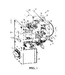
FIG. 1 is a top perspective view of one illustrative embodiment of a rear-
facing
poultry claw system as described herein.
FIG. 2 is a top view of the rear-facing poultry claw system of FIG. 1.
FIG. 3 is a left side view of the rear-facing poultry claw system of FIGS. 1
and 2
with the left side plate removed to expose components of the poultry detection
system.
FIG. 4 is a left side view of the rear-facing poultry claw system of FIGS. 1-
3, with
a bird restrained in a poultry cradle in a selected position relative to the
system.
FIG. 5 is an enlarged top perspective view of the poultry detection system of
FIG.
4.
17
CA 03235285 2024-04-11
WO 2023/075841 PCT/US2022/026468
FIG. 6 is a perspective view of one illustrative embodiment of a poultry
cradle that
can be used in connection with the rear-facing poultry claw systems as
described herein.
FIG. 7 is front plan view of the poultry cradle of FIG. 6.
FIG. 8 is a side plan view of the poultry cradle of FIG. 6.
FIG. 9 is an enlarged view of the shank guides and shank clamps of the poultry
cradle of FIG. 6.
FIG. 10 depicts the poultry detection system of FIG. 4 after movement of a
seat lift
to act on the bird restrained in the poultry cradle.
FIG. 11 depicts the rear-facing poultry claw system of FIG. 10 after movement
of
.. the toe control bar to a control position and movement of a sensor track to
a sensing
position from the base position as depicted in FIG. 10.
FIG. 12 depicts the rear-facing poultry claw system of FIG. 11 after movement
of
the claw sensor to a forward position from a home position as seen in FIG. 11.
FIG. 13 depicts the rear-facing poultry claw system of FIG. 12 after movement
of
the sensor track to a finish position from the sensing position as seen in
FIG. 12.
FIG. 14 depicts the rear-facing poultry claw system of FIG. 13 after movement
of
the sensor track to its base position, movement of the toe control bar to its
retracted
position, movement of the claw sensor to its home position on the sensor
track, and
movement of the seat lift away from the bird restrained in the poultry cradle.
FIG. 15 is a top perspective view of one illustrative embodiment of a claw
sensor
that can be used in one or more embodiments of a rear-facing poultry claw
systems as
described herein.
FIG. 16 is a front end view of the claw sensor of FIG. 15.
FIG. 17 depicts a portion of another illustrative embodiment of a bird
restrained in
a poultry cradle in a selected position relative to a rear-facing poultry claw
system as
described herein before movement of a seat lift to act on the bird restrained
in the poultry
cradle.
FIG. 18 depicts the poultry cradle and seat lift of FIG. 17 after movement of
the
seat lift to act on the bird restrained in the poultry cradle.
18
CA 03235285 2024-04-11
WO 2023/075841 PCT/US2022/026468
FIG. 19 depicts one illustrative embodiment of a rear-facing poultry claw
system as
described herein with the poultry cradle of FIG. 18 in a selected position
with respect to
the system and the illustrative embodiment of a toe control bar of the system
in its
retracted position.
FIG. 20 depicts the forward-facing toes and the rear-facing toe on the right
shank of
the bird in the poultry cradle of FIG. 19 after the toe control bar has been
moved to its
control position to raise the forward-facing toes of the bird.
FIG. 21 depicts the forward-facing toes and the rear-facing toe on the right
shank of
the bird in the poultry cradle of FIG. 20 after the claw sensor in its forward
position to
position the detection apparatus of claw sensor proximate the shank of the
bird B.
FIG. 22 is a schematic diagram of components in one illustrative embodiment of
a
rear-facing poultry claw system as described herein.
FIG. 23 is a schematic diagram of one illustrative embodiment of a system as
described herein that includes multiple poultry cradles, a loading station,
and unloading
station, and one illustrative embodiment of a rear-facing poultry claw system
along with
locations for one or more additional stations.
While the above-identified figures (which may or may not be drawn to scale)
set
forth embodiments of the invention, other embodiments are also contemplated,
as noted in
the discussion. In all cases, this disclosure presents the invention by way of
representation
and not limitation. It should be understood that numerous other modifications
and
embodiments can be devised by those skilled in the art, which fall within the
scope of this
invention.
DESCRIPTION OF ILLUSTRATIVE EMBODIMENTS
Before any illustrative embodiments are described in detail, it is to be
understood
that the invention is not limited in its application to the details of
construction and the
arrangement of components set forth in the following description or
illustrated in the
figures of the drawing. The invention is capable of other embodiments and of
being
practiced or of being carried out in various ways.
19
CA 03235285 2024-04-11
WO 2023/075841 PCT/US2022/026468
FIGS. 1-3 are views of one illustrative embodiment of a rear-facing poultry
claw
system 10 that may be used to detect the claws of the rear-facing toes on
shanks of a bird
as described herein. FIG. 1 is a top perspective view of the illustrative
system 10, FIG. 2 is
a top view of the system 10 and FIG. 3 is a left side view of the system 10
with the left side
plate removed to expose components of the rear-facing poultry claw system 10.
The rear-facing poultry claw system 10 includes a seat lift 20, toe control
bar 30,
claw sensor 40, and claw sensor carriage 50 mounted on a sensor track which,
in the
depicted embodiment, is constituted by rail assembly 52. These components are
all
mounted on a system frame that includes a base plate 12 and pair of side
plates 16 attached
to and extending away from the base plate 12. In one or more embodiments, the
base plate
12 of the system frame may be configured for attachment to a larger system
capable of
processing many birds. Some illustrative examples of such systems may be
described in,
e.g., U.S. Patent No. 7,066,112, titled AUTOMATED POULTRY PROCESSING
METHOD AND SYSTEM.
In the depicted illustrative embodiment, the seat lift 20 includes a lift end
22
configured to contact the seat of a bird B restrained in a poultry cradle C10
located in a
selected position relative to the system frame and, therefore, the components
of the rear-
facing poultry claw system 10. The seat lift 20 is operably attached to the
system frame
and is configured to move between a ready position (seen in, e.g., FIGS. 1-5
and 14) and a
lift position (seen in, e.g., FIGS. 10-13). The depicted seat lift 20 is
configured to rotate
about a lift axis 21 when moving between the ready position and the lift
position, but
motion other than rotation can be used to move the seat lift 20 between its
ready and lift
positions.
The depicted illustrative embodiment of rear-facing poultry claw system 10
includes a seat lift actuator 28 operably connected to the seat lift 20.
Operation of the seat
lift actuator 28 moves the seat lift 20 from its ready position as seen in,
e.g., FIG. 5 to its
lift position as seen in, e.g., FIG. 10. In the depicted illustrative
embodiment, seat lift
actuator 28 is in the form of a pneumatic piston/cylinder that extends and
retracts to move
the seat lift 20 between its ready and lift positions. The depicted
illustrative embodiment of
CA 03235285 2024-04-11
WO 2023/075841 PCT/US2022/026468
seat lift actuator 28 is only one example of an actuator that may be used to
move the seat
lift 20 between its ready and lift positions. Examples of potentially useful
alternative
actuators include, but are not limited to, a piston/cylinder operated
hydraulically,
pneumatically, using a solenoid, etc., a motor with or without a gear assembly
(e.g., a rack
and pinion, etc.), magnetic/electromagnetic linear actuators, rotary actuators
(e.g.,
pneumatic actuators, magnetic/electromagnetic actuators, etc.), etc.
The depicted illustrative embodiment of rear-facing poultry claw system 10
also
includes a toe control bar 30 operably attached to the system frame (which, in
the depicted
illustrative embodiment, includes base plate 12 and side plates 16). The toe
control bar 30
is configured to move between a retracted position (as seen in, e.g., FIGS. 1-
5, 10, and 14)
and a control position (as seen in, e.g., FIGS. 11-13). In the depicted
illustrative
embodiment, toe control bar 30 is configured to rotate about a control bar
axis 31 when
moving between the retracted position and the control position, but motion
other than
rotation can be used to move the toe control bar 30 between its retracted and
control
positions.
The depicted illustrative embodiment of toe control bar 30 includes a frame 32
attached to side plates 16 of the system frame and toe platform 34 mounted
centrally on the
frame 32 such that the toe platform 34 is located proximate the claw sensor 40
when the
claw sensor 40 is in its forward position as described herein. As a result,
the toe platform
34 is configured to control and support the forward-facing toes of a bird
during detection
of the rear-facing toes on the shanks of a bird as described herein.
The depicted illustrative embodiment of rear-facing poultry claw system 10
includes a control bar actuator 38 operably connected to the toe control bar
30. Operation
of the control bar actuator 38 moves the toe control bar 30 from its retracted
position as
seen in, e.g., FIG. 10, to its control position as seen in, e.g., FIG. 11. In
the depicted
illustrative embodiment, the control bar actuator 38 is in the form of a
pneumatic cylinder
that extends and retracts to move the toe control bar 30 between its retracted
and control
positions. The depicted illustrative embodiment of control bar actuator 38 is
only one
example of an actuator that may be used to move the toe control bar 30 between
its
21
CA 03235285 2024-04-11
WO 2023/075841 PCT/US2022/026468
retracted and control positions. Examples of potentially useful alternative
actuators
include, but are not limited to, a piston/cylinder operated hydraulically,
using a solenoid,
etc., a motor with or without a gear assembly (e.g., a rack and pinion, etc.),
magnetic/electromagnetic linear actuators, rotary actuators (e.g., pneumatic
actuators,
.. magnetic/electromagnetic actuators, etc.), etc.
The depicted illustrative embodiment of rear-facing poultry claw system 10
also
includes a claw sensor 40 operably attached to the system frame which, in the
depicted
illustrative embodiment, includes a base plate 12 and side plates 16. The claw
sensor 40 is
attached to and supported above a carriage 50. In the depicted embodiment, the
claw
sensor 40 is attached to carriage 50 using clamps 49 (see, e.g., FIGS. 3 and
5).
With reference to FIG. 15 as well as FIGS. 1-3, the depicted illustrative
embodiment of claw sensor 40 includes a pair of radiofrequency (RF) energy
applicators
70 which can be used to detect the rear-facing toes on one or both shanks of
birds as
described herein. Although the depicted embodiment of claw sensor 40 includes
a pair of
RF energy applicators 70, one or more alternative embodiments may include only
a single
RF energy applicators 70 positioned to detect the rear-facing toe on either
the left or right
side of a bird. One advantage of providing a pair of RF energy applicators 70
arranged to
detect rear-facing toes on both the left and right shanks of a bird is that
both rear-facing
toes can be detected at the same time using a rear-facing poultry claw system
as described
.. herein.
The illustrative embodiment of the rear-facing poultry claw system 10 also
includes
a sensor track operably attached to the system frame which, in the depicted
illustrative
embodiment, includes the base plate 12 and side plates 16. In the depicted
illustrative
embodiment, the sensor track is defined by rail assembly 52 including two
rails that
extends away from the base plate 12 between the side plates 16. Carriage 50 is
configured
to move along the sensor track/rail assembly 52. Because claw sensor 40 is
attached to
carriage 50, movement of carriage 50 along the sensor track/rail assembly 52
causes
corresponding movement of the claw sensor 40 along the sensing axis 41 that is
aligned
with the sensor track/rail assembly 52.
22
CA 03235285 2024-04-11
WO 2023/075841 PCT/US2022/026468
In the depicted embodiment, carriage 50 is operably attached to a claw sensor
actuator in the form of a motor assembly 56 configured to operate on a belt 54
aligned with
the toe sensing axis 41 and rails 52. The carriage 50 is operably attached to
the belt 54
such that movement of the belt 54 in a direction aligned with the sensing axis
41 moves the
carriage 50 and attached claw sensor 40 along the sensing axis 41.
The claw sensor actuator is, in the depicted illustrative embodiment, in the
form of
a motor assembly 56 operating on belt 54. The depicted embodiment of motor
assembly 56
is in the form of a stepper motor operably connected to a controller 14 as
described herein.
In one or more alternative embodiments, however, motor assembly 56 may be
provided in
the form of any other electric/electromagnetic motor, pneumatic motor,
hydraulic motor,
etc.
Although the claw sensor actuator is, in the depicted illustrative embodiment,
in the
form of a motor assembly operating on belt 54, any suitable combination of
components
configured to move the carriage 50 and attached claw sensor 40 along the
sensing axis 41
could be used in place of the depicted motor assembly 56 and belt 54. Suitable
alternatives
providing linear motion to move the carriage 50 and claw sensor 40 may
include, but are
not limited to, pistons or cylinders (e.g., hydraulic, pneumatic, solenoid-
driven, etc.),
motor assemblies combined with lead screws and followers, a rack and pinion,
etc.
As will be described herein, the claw sensor 40 is mounted on the sensor track
and
configured to move along the sensing axis 41 between a home position (as seen
in, e.g.,
FIGS. 4, 5, 10-11, and 14) and a forward position (as seen in, e.g., FIGS. 12-
13). In the
home position, the claw sensor 40 is located further from the toe platform 34
on toe control
bar 30 (when toe control bar 30 is in its control position) than when the claw
sensor 40 is
in the forward position.
The depicted illustrative embodiment of the rear-facing poultry claw system 10
also
includes a track actuator operably connected to the sensor track (which, in
the depicted
embodiment, is in the form of rail assembly 52) and configured to move the
sensor
track/rail assembly 52 between a base position, and a finish position. Because
the claw
sensor 40 is mounted on carriage 50 which moves along sensor track/rail
assembly 52,
23
CA 03235285 2024-04-11
WO 2023/075841 PCT/US2022/026468
movement of the sensor track/rail assembly 52 between the base, sensing, and
finish
positions moves the sensing axis 41 along with the claw sensor 40 and carriage
50 between
those positions as well.
The track actuator in the depicted illustrative embodiment of system 10 is
seen in,
e.g., FIGS. 3 and 4 and includes a motor assembly 58 operable on a drive link
59 to move
the end of the rail assembly 52 of the sensor track relative to the base plate
12 between the
base, sensing, and finish positions. In the sensing position, the sensor
track/rail assembly
52 is located closer to the seat lift 20 and lift axis 21 than when the sensor
track/rail
assembly 52 is in either of its base or finish positions. Although the
depicted embodiment
of the sensor track/rail assembly 52 rotates about track axis 51 when moving
between the
base, sensing, and finish positions, in one or more alternative embodiments,
the sensor
track/rail assembly 52 and components carried thereon may be moved towards and
away
from the seat lift 20 and seat lift axis 21 through translational motion or a
combination of
rotation and translation.
Motor assembly 58 of the depicted illustrative embodiment of a track actuator
may
be in the form of a stepper motor or other rotary device capable of providing
precisely
controlled movement of the sensor track/rail assembly 52 between its base,
sensing, and
finish positions using drive link 59.
Although motor assembly 58 and drive link 59 form one illustrative embodiment
of
a track actuator that may be used in one or more embodiments of the rear-
facing poultry
claw systems described herein, the track actuators used in the rear-facing
poultry claw
systems described herein may take many other forms including, but not limited
to, pistons
or cylinders (e.g., hydraulic, pneumatic, solenoid-driven, etc.), motor
assemblies combined
with lead screws and followers, a rack and pinion, etc.
The illustrative embodiment of rear-facing poultry claw system 10 is depicted
in
FIGS. 4 and 5 along with a poultry cradle C10 in which a bird B is restrained
(preferably
atraumatically). The poultry cradle C10 is located in a selected position
relative to the
system frame (i.e., represented by base plate 12 and side plate 16 in FIG. 4)
such that the
seat lift 20, toe control bar 30, and claw sensor 40 can be used to detect the
rear-facing toes
24
CA 03235285 2024-04-11
WO 2023/075841 PCT/US2022/026468
on the shanks of the bird B restrained in the poultry cradle C10. Although
depicted in
space, i.e., not attached to any other components, it should be understood
that the poultry
cradle C10 will preferably be carried on a carrier system such as, e.g., a
belt, chain, etc. In
some embodiments, however, the poultry cradle C10 may be manually placed on a
stationary holder such that the poultry cradle C10 is in the selected position
relative to the
system frame.
The illustrative embodiment of poultry cradle C10 is depicted separately in
FIGS.
6-9 in the absence of the bird B as seen in FIGS. 4 and 5. The poultry cradle
C10 is
depicted in a perspective view in FIG. 6, a front plan view in FIG. 7, and a
side plan view
in FIG. 8 (similar to the view of cradle C10 in FIG. 4). The end of the
poultry cradle is
depicted in an enlarged view in FIG. 9. The depicted poultry cradle C10
includes a torso
support C40, a pair of shank control apparatus each including a shank clamp
C50 and and
optional shank guide C60, and an optional head support C70. The various
components
may be operably attached in a manner that provides for atraumatic restraint of
a bird
positioned in the poultry cradle C10.
In one or more embodiments, the torso support C40 includes a support surface
C42
shaped to generally follow the anatomical shape of the torso of a bird located
in the poultry
cradle C10 such that the torso of the bird is generally evenly supported. As a
result, the
shape of the support surface C42 may be different depending on the breed, age,
gender,
etc. of the birds that are to be restrained in the poultry cradle C10.
The shank control apparatus are provided and positioned to restrain the left
and
right shanks of a bird having its torso supported by the torso support C40.
Each shank
control apparatus includes a shank clamp C50 positioned to retain a shank of a
bird at a
location below the joint commonly referred to as the "hock" joint and above
the joints of
the forward-facing toes at the distal/inferior end of the shank, while the
optional shank
guide C60 is positioned to act on the shank above or proximal/superior to the
shank clamp
C50.
While the shank clamps C50 prevent the bird from moving its shank in any
direction other than along the length of its shank (aligned with axes C51),
the depicted
CA 03235285 2024-04-11
WO 2023/075841 PCT/US2022/026468
illustrative embodiments of shank guides C60 can help to limit or prevent
movement of the
shanks contained therein along the lateral and medial directions of the
restrained bird. The
shank guides C60 include a slot C62 configured to receive a shank of bird
positioned in the
shank clamp C50 located below/inferior to the shank guide C60. Because the
shank guide
is in the form of a slot C62, the shank guide C60 alone cannot restrain
movement of a
shank of a restrained bird in the dorsal (rearward) direction.
The combined two-point restraint of the shanks by the shank clamps C50 and
shank
guides C60 (in addition to supporting their torsos and restraining their
heads) can provide
additional control over the hock joints of a restrained bird at the
proximal/superior ends of
the shanks and the distal/inferior ends of the shanks. That additional control
over the
shanks and forward-facing toes/phalanges may be needed when, for example, the
rear-
facing toes of birds are to be accurately positioned for detection using a
rear-facing poultry
claw system as described herein.
Spacing between the inferior/distal/bottom side C53 of the shank clamps C50
and
the inferior/distal/bottom side C63 of the shank guides C60 may be helpful for
larger birds.
With reference to FIG. 9, the spacing d (along axes C51) between the
inferior/distal/bottom
side C63 of the shank clamp C50 from the inferior/distal/bottom side C63 of
the shank
guide C60 may improve control over the shank of a duck or a turkey hatchling
that would
otherwise not be available in the absence of a shank guide and/or if the shank
guide and the
shank clamp were located closer to each other.
In one or more embodiments, the distance between an inferior/ distal/bottom
side
C53 of the shank clamp C50 and the inferior/ distal/bottom side C63 of the
shank guide
C60 along a longitudinal (superior/inferior) axis C11 extending through the
head support
C70 and the torso support C40 is, at a lower end, 5 millimeters or more, 1
centimeter or
more, or 2 centimeters or more.
In one or more embodiments, the distance between an inferior/distal/bottom
side
C53 of the shank clamp C50 and the inferior/distal/bottom side C63 of the
shank guide
C60 along a longitudinal (superior/inferior) axis C11 extending through the
head support
26
CA 03235285 2024-04-11
WO 2023/075841 PCT/US2022/026468
C70 and the torso support C40 is, at an upper end, 3 centimeters or less, 2
centimeters or
less, or 1 centimeter or less.
In one or more embodiments, the shank clamps C50 may include arms C52 that
move between open configurations in which the shanks of a bird can be
positioned in the
shank clamps C50 and closed configurations in which the shanks of the bird are
retained in
the shank clamps C50. Although the depicted shank clamps C50 include arms C52,
other
structures (such as, e.g., inflatable bladders, etc.) may be used to retain a
bird's shanks in
the shank clamps when the clamps C50 are in the closed configuration.
The shank clamps C50 may be normally closed but constructed such that they
open
in response to the forces generated as a shank is being inserted into the
shank clamp C50
(the shank clamps C50 may be, e.g., spring-loaded, etc.). In other
embodiments, the shank
clamps C50 may have defined open and closed configurations between which the
clamps
can be moved to accept and/or retain a shank of a bird being restrained. In
one or more
embodiments, the arms C52 of the shank clamps may rotate about clamp axes C51
when
.. moving between the open and closed configurations.
The poultry cradles C10 may also include a head support C70 operably attached
to
the torso support C40 and positioned to support the head of a bird located in
the poultry
cradle C10. The head support C70 includes a first side facing the head of a
bird retained in
the poultry cradle C10. The head support C70 may preferably include a beak
receiving
passage C72 extending through the head support C70 to an opening C73 on the
second side
of the head support C70. In one or more embodiments, the beak receiving
passage C72
preferably extends through the head support C70 such that at least a portion
of the beak of
a bird retained in the poultry cradle C10 extends through the opening C73 of
the beak
receiving passage C72 and is exposed proximate the second surface of the head
support
C70 (where the second side of the head support C70 faces away from the head of
a bird
retained in the poultry cradle C10).
The head support C70 may include head clamps C74 movable between an open
configuration and a closed configuration. In the open configuration, the head
clamp C74 is
preferably positioned such that the head of a bird can be positioned in the
head support
27
CA 03235285 2024-04-11
WO 2023/075841 PCT/US2022/026468
C70 with the beak preferably extending through the beak receiving passage C72
and
preferably protruding from the opening C73 on the second side of the head
support C70.
In the closed configuration, the head clamps C74 preferably function to retain
the head of a
bird in the head support C70 such that its beak extends into the beak
receiving passage C72
and preferably protrudes through the opening C73 on the second side of the
head support.
The head clamps C74 may rotate about head clamp axes C71 when moving between
their
open and closed configurations.
Structures similar to the head support C70 and clamps C74 may be described in,
e.g., U.S. Patent No. 5,651,731 titled METHOD AND APPARATUS FOR DEBEAKING
POULTRY; U.S. Patent No. 7,232,450 titled APPARATUS AND METHOD FOR UPPER
AND LOWER BEAK TREATMENT; U.S. Patent Application Publication US
2005/0101937 Al titled APPARATUS AND METHOD FOR NASAL DELIVERY OF
COMPOSITIONS TO BIRDS; U.S. Patent No. 7,363,881 titled BEAK TREATMENT
WITH TONGUE PROTECTION; etc. Another illustrative embodiment of a head clamp
used with a head holder in a poultry cradle includes the keeper apparatus
described in US
Patent 9,808,328 (POULTRY CARRIERS AND METHODS OF RESTRAINING
POULTRY). Other examples of suitable structures for head clamps are also
possible.
As noted above, the rear-facing poultry claw system 10 is depicted in FIGS. 4
and 5
with bird B restrained in the poultry cradle C10 located in a selected
position relative to the
rear-facing poultry claw system 10. The seat lift 20 of system 10 is located
in its ready
position, toe control bar 30 is in its retracted position, and claw sensor 40
is located in its
home position as described above in connection with rear-facing poultry claw
system 10.
Referring to FIG. 10, the seat lift 20 is moved from its ready position to its
lift
position where it acts on the seat of the bird B to raise the seat of the bird
B causing the
shanks of the bird B to move upward. For purposes of the present invention,
the seat of the
bird is located proximate the cloaca or vent of the bird and is located to
allow for
positioning of a bird B in a poultry cradle as described herein. Movement of
the seat lift 20
to its lift position raises the shanks of the bird B such that the
distal/inferior ends of the
shanks of the bird B are moved to a location just below the
inferior/distal/bottom sides C53
28
CA 03235285 2024-04-11
WO 2023/075841 PCT/US2022/026468
of the shank clamps C50. As a result, the forward-facing toes and the rear-
facing toes (and
their claws) on the shanks of the bird B are positioned in known locations
relative to the
remainder of the rear-facing poultry claw system 10.
In the depicted illustrative embodiment of rear-facing poultry claw system 10,
movement of the seat lift 20 from its ready position to its lift position is
accomplished
using seat lift actuator 28. In particular, seat lift actuator 28 is extended
which rotates the
seat lift 20 about lift axis 21 from its ready position to its lift position.
That rotation of seat
lift 20 causes the lift end 22 to contact and raise the bird B restrained in
the poultry cradle
C10. As noted above, movement of the bird by seat lift 20 positions the shanks
and the
forward-facing toes of the bird in a known location relative to the remainder
of the rear-
facing poultry claw system 10.
After actuation of the seat lift 20 to raise the bird B in the poultry cradle
C10 as
discussed in connection with FIG. 10 such that the forward-facing toes are
positioned in
known locations, the toe control bar 30 (and its toe platform 34) can be moved
from its
retracted position to its control position to raise the forward-facing toes of
the bird B as
seen in FIG. 11. Raising the forward-facing toes of the bird B while
restraining the shanks
of the bird B typically causes the rear-facing toes on the shanks of the bird
B to extend
away from the shank to make detection of the claws on those rear-facing toes
easier. In
addition, extension of those rear-facing toes may also provide benefits in
inspection and or
processing of the claws on those rear-facing toes as compared to the claws on
rear-facing
toes that are located closer to the shanks of the bird B.
In addition to movement of the toe control bar 30 from its retracted position
to its
control position as seen in one change from FIG. 10 to FIG. 11, the depicted
illustrative
embodiment of the sensor track/rail assembly 52 is also moved from its base
position as
seen in FIG. 10 to its sensing position in FIG. 11. Movement of the sensor
track/rail
assembly 52 to its sensing position as seen in FIG. 11 involves, in the
depicted illustrative
embodiment, rotating the sensor track/rail assembly about track axis 51.
Movement of the
sensor track/rail assembly 52 to its sensing position as seen in FIG. 11 also
raises the
carriage 50 and claw sensor 40 located on sensor track/rail assembly 52 as
seen in FIG. 11.
29
CA 03235285 2024-04-11
WO 2023/075841 PCT/US2022/026468
With reference to FIG. 12, the claw sensor 40 is moved along the sensing axis
41
from its home position on sensor track/rail assembly 52 as seen in FIG. 11 to
its forward
position as seen in FIG. 12. With the claw sensor 40 in its forward position
on the sensor
track/rail assembly 52 and the sensor track/rail assembly 52 in its sensing
position, the
detection apparatus on claw sensor 40 is preferably positioned proximate the
shanks of the
bird B at a location below the shank clamps C50 of the poultry cradle C10 and
at or above
the rear-facing toes on the shanks of the bird B.
With the claw sensor 40 in its forward position and sensor track/rail assembly
52 in
its sensing position, the track actuator (including motor assembly 58 and
drive link 59 in
the depicted embodiment) can be operated to move the sensor track/rail
assembly 52 and
claw sensor 40 located thereon away from the poultry cradle C10 while
operating the
detection apparatus on the claw sensor 40 to detect the claws on the rear-
facing toes on the
shanks of the bird B. In essence, the detection apparatus of the claw sensor
40 (in one
illustrative embodiment) scans the rear-facing toes thereon to detect the
claws at the distal
ends of the rear-facing toes when the sensor track is moved from the sensing
position to
the finish position. The finish position will correspond to a location at
which the detection
apparatus on the claw sensor 40 detects the claws at the distal ends of the
rear-facing toes.
In those instances in which the claws on the rear-facing toes on the left and
right shanks
are located at different distances from the sensing axis 41, the system may be
configured to
position the claw sensor at a midpoint between the relative positions of the
claws on the
left and right rear-facing toes.
In the depicted illustrative embodiment, the forward position of the claw
sensor 40
in one or more embodiments of the rear-facing poultry claw systems described
herein may
be variable between each bird, with the exact forward position being based on
detection of
one or more anatomical features (e.g., the shanks, rear-facing toes, and/or
claws) of each
bird. In such embodiments, the specific forward position may be based on,
e.g., detection
of the shanks, rear-facing toes, and/or claws by the detection apparatus on
the claw sensor
40.
CA 03235285 2024-04-11
WO 2023/075841
PCT/US2022/026468
In one or more alternative embodiments of rear-facing poultry claw systems
described herein, the claw sensor 40 may be positioned at a selected forward
position, in
other words, the system does not move the claw sensor 40 to the selected
forward position
based on detection of any anatomical features of a specific bird. Any such
selected forward
position may be chosen based on, e.g., one or more anatomical characteristics
of a selected
set of birds, e.g., birds of a given flock being processed.
The finish position of the sensor track/rail assembly in the depicted
illustrative
embodiment of the rear-facing poultry claw system may, like the forward
position of the
claw sensor 40, also be variable between each bird, with the exact finish
position being
based on detection of one or more anatomical features of each bird. In such
embodiments,
the specific finish position may be based on, e.g., detection of the claws on
the rear-facing
toes by the detection apparatus on the claw sensor 40. In one or more
alternative
embodiments of rear-facing poultry claw systems described herein, the sensor
track/rail
assembly 52 may be positioned at a selected sensing/finish position, in other
words, the
system does not move the sensor track/rail assembly 52 to the selected
sensing/finish
position based on detection of the claws at the distal ends of rear-facing
toes of birds. Any
such selected sensing/finishing position may be chosen based on, e.g., one or
more
anatomical characteristics of a selected set of birds, e.g., birds of a given
flock being
processed.
After positioning of the claw sensor 40 and the sensor track/rail assembly 52
as
described herein, any selected activity or activities such as, e.g.,
inspections, processing,
etc. of the claws on the rear-facing toes can be performed. At the completion
of those
activities, with the claw sensor 40 in forward position along the sensing axis
41 and the
sensor track/rail assembly 52 in its finish position as seen in FIG. 13, the
components of
the rear-facing poultry claw systems described herein can be returned to their
respective
"ready" positions. Those changes can be seen in FIG. 14 where the seat lift 20
is returned
to its ready position from its lift position as seen in FIG. 13, the toe
control bar 30 is
returned to its retracted position from its control position as seen in FIG.
13, the claw
sensor 40 is returned to its home position along sensing axis 41 on sensor
track/rail
31
CA 03235285 2024-04-11
WO 2023/075841 PCT/US2022/026468
assembly 52 from its forward position as seen in FIG. 13, and the sensor
track/rail
assembly 52 is returned to its base position from its finish position as seen
in FIG. 13. With
the components of the rear-facing poultry claw system returned to their ready
positions, the
bird B in the poultry cradle C10 can be moved out of the selected position
relative to the
system frame.
One illustrative embodiment of claw sensor 40 seen in connection with the
illustrative embodiments of rear-facing poultry claw system described herein
is depicted in
enlarged views in FIGS. 15-16 after removing the claw sensor 40 from the
carriage 50 of
the illustrative embodiments of rear-facing poultry claw systems described
herein. The
.. depicted illustrative embodiment of claw sensor 40 contains a pair of
detectors 70 carried
in a housing 42 that includes a cover plate 43 attached to the housing 42. For
reference, the
sensing axis 41 is also depicted in FIGS. 15-16.
The detectors 70 of the depicted embodiment of claw sensor 40 are arranged and
configured to be positioned proximate the rear-facing toes on the shanks of a
bird B
restrained in a poultry carrier located in a selected position with respect to
the system
frame of a rear-facing poultry claw system as described herein. Although the
depicted
illustrative embodiment of claw sensor 40 includes a pair of detectors 70
configured to be
simultaneously located proximate the left and right shanks of a bird B in a
poultry carrier
as described herein, one or more alternative embodiments of claw sensors that
may be used
in rear-facing poultry claw systems described herein may include only one
detector
configured to detect the claw on the rear-facing toe on only one shank of a
bird. In
embodiments such as that seen in, e.g., FIGS. 15-16, the two detectors 70 are
provided to
simultaneously detect claws on the rear-facing toes on both the left and right
shank of a
bird.
In one or more embodiments, the detectors 70 of the depicted illustrative
embodiment of toe sensor 40 may be adapted to both detect and, optionally,
deliver energy
to the claws on the rear-facing toes using the systems described herein. For
example, the
detectors 70 of the claw sensor 40 may function as applicators that are
configured to
establish radio frequency (RF) electric fields that can be used for either or
both the
32
CA 03235285 2024-04-11
WO 2023/075841 PCT/US2022/026468
detection of poultry claws and selective delivery of RF energy to the claws on
the rear-
facing toes of birds after detection. In one or more embodiments, the energy
delivered to
the rear-facing claws on birds as described herein may be sufficient to retard
growth of the
rear-facing claws.
Some illustrative systems and methods in which RF energy delivered through
applicators is used in connection with the detection and/or delivery growth-
retarding
levels/amounts of energy to claws of birds is described in, e.g.,
International Publication
No. WO 2019/236964 titled ENERGY DELIVERY SYSTEM USING AN ELECTRIC
FIELD (Gorans et al.) (claiming priority to US Provisional Patent Application
No.
62/682,262 filed on 8 June 2018). In those embodiments of claw sensor 40 in
which the
detector 70 functions as an applicator to deliver RF energy as part of the
detection process,
the housing 42 or cover plate 43 of the claw sensor 40 may function as a
ground for energy
being delivered through the detectors 70.
FIGS. 17-21 depict another illustrative embodiment of a rear-facing poultry
claw
system as described herein in use. In particular, FIG. 17 depicts a bird B
restrained in a
poultry cradle C110 in a selected position relative to the system. The left
shank of the bird
B is located in the shank clamp C150 and the shank guide C160. The system
depicted in
FIG. 17 includes a seat lift 120 in its ready position before movement of the
seat lift 120 to
act on the bird B restrained in the poultry cradle C110.
FIG. 18 depicts the rear-facing poultry claw system of FIG. 17 after movement
of
the seat lift 120 from its ready position to its lift position in which the
seat lift 120 acts on
the bird B restrained in the poultry cradle C110. As described herein,
movement of the seat
lift 120 from its ready position to its lift position as depicted in FIG. 18
causes the shanks
of the bird B to move upward such that the forward-facing toes of the bird B
and the
distal/inferior ends of the shanks of the bird B are moved to a location just
below the
inferior/distal/bottom sides of the shank clamps C150 of poultry cradle C110.
As a result,
the forward-facing toes and the rear-facing toes on the shanks of the bird B
are positioned
in known locations relative to the remainder of the rear-facing poultry claw
system.
33
CA 03235285 2024-04-11
WO 2023/075841 PCT/US2022/026468
FIG. 19 depicts the illustrative embodiment of rear-facing poultry claw system
with
the bird B in the poultry cradle of FIG. 18 in a selected position with
respect to the system
(and the seat lift 120 in its lift position) and a toe control bar 130 in its
retracted position
within the system (and relative to the bird B in the poultry cradle C110). The
forward-
facing toes FT and the rear-facing toe RT of the bird B are also depicted in
FIG. 19.
FIG. 20 depicts the forward-facing toes FT and the rear-facing toe RT on the
right
shank of the bird in the poultry cradle C110 of FIG. 19 after the toe control
bar 130 has
been moved to its control position to raise the forward-facing toes FT of the
bird B towards
the poultry cradle C110. As discussed herein, movement of the forward-facing
toes FT by
the toe control bar 130 preferably causes the rear-facing toe RT on the shank
to extend
away from the shank. Movement of the forward-facing toes FT by the toe control
bar 130
may also/alternatively simply move the forward-facing toes FT away from the
rear-facing
toe RT to enhance detection of the rear-facing toe RT.
With the forward-facing toes FT moved by the toe control bar 130 and the rear-
facing toe RT on the shank extending away from the shank as seen in FIG. 20,
the claw
sensor 140 can be moved to its forward position as depicted in FIG. 21. In
addition,
positioning the claw sensor 140 as seen in FIG. 21 may also involve moving the
sensor
track/rail assembly (not shown) on which the claw sensor 140 is located from
its base
position to its sensing position.
Movement of the claw sensor 140 and the sensor track/rail assembly to position
the
claw sensor 140 as depicted in FIG. 21 may involve, as described herein,
movement of the
claw sensor 140 to a selected forward position or to a forward position that
varies based on
detection of one or more anatomical features of the bird B.
Similarly, movement of the sensor track/rail assembly carrying the claw sensor
140
to the position depicted in FIG. 21 may involve, as described herein, movement
of the
sensor track/rail assembly carrying claw sensor 140 to a selected
sensing/finish position or
from a sensing position to a finish position that varies based on detection of
one or more
anatomical features of the bird B. In one or more embodiments of the rear-
facing poultry
claw systems described herein in which the finish position varies, the claw
sensor 140 and
34
CA 03235285 2024-04-11
WO 2023/075841 PCT/US2022/026468
the sensor track/rail assembly may be moved to their respective forward
position and
sensing position to position the detection apparatus on the claw sensor 140 at
a location on
or above/proximal the rear-facing toe RT.
With the claw sensor 140 in its forward position and the sensor track/rail
assembly
in its sensing position, the sensor track/rail assembly can be moved along the
directions
indicated by bidirectional arrow A in FIG. 21 to a location at which the
detection apparatus
of the claw sensor detects the claws on the rear-facing toes RT of the bird B.
In one or
more embodiments, the system may be configured to position the claw sensor 140
(and the
detection apparatus thereon) at a midpoint between the relative detected
positions of the
claws on the left and right rear-facing toes RT on the left and right shanks
of the bird B.
FIG. 22 is a schematic diagram of components in one illustrative embodiment of
a
rear-facing poultry claw system as described herein. The depicted system
includes a
controller 200 operably connected to a seat lift actuator 228, a control bar
actuator 238, a
claw sensor actuator 256, and a track actuator 257.
The seat lift actuator 228 is operably connected to a seat lift 220 of the
rear-facing
poultry claw systems described herein. As described herein, the seat lift
actuator 228 is
used to move the seat lift 220 between its ready and lift positions.
The control bar actuator 238 is operably connected to a toe control bar 230 of
the
rear-facing poultry claw systems described herein. As described herein, the
control bar
actuator is used to move the toe control bar 230 between its retracted and
control positions.
The claw sensor actuator 256 is operably connected to a claw sensor 240 of the
rear-facing poultry claw systems described herein. As described herein, the
claw sensor
actuator 256 is used to move the claw sensor 240 between its home and forward
positions
along a sensing axis.
The track actuator 258 is operably connected to a sensor track along which the
claw
sensor 240 of the rear-facing poultry claw systems described herein moves. As
described
herein, the track actuator 258 is used to move the sensor track between its
base, sensing,
and finish positions to assist in detection of the claws on the rear-facing
toes of a bird.
CA 03235285 2024-04-11
WO 2023/075841 PCT/US2022/026468
The controller 200 may be provided in any suitable form and may, for example,
include memory and a controller. The controller may, for example, be in the
form of one
or more microprocessors, Field-Programmable Gate Arrays (FPGA), Digital Signal
Processors (DSP), microcontrollers, Application Specific Integrated Circuit
(ASIC) state
machines, etc. The controllers may include one or more of any suitable input
devices
configured to allow a user to operate the poultry toe and claw systems
described herein
(e.g., keyboards, touchscreens, mice, trackballs, etc.), as well as display
devices configured
to convey information to a user (e.g., monitors (which may or may not be
touchscreens),
indicator lights, etc.). Although not depicted separately, the controller 200
may
incorporate a pneumatic and/or hydraulic control system in those systems in
which one or
more of the actuators use pneumatic and/or hydraulic components.
The illustrative embodiment of the rear-facing poultry claw system depicted in
FIG. 22 also includes a pair of detectors 270 designated for the anatomical
features (e.g.,
rear-facing toes and/or claws on the rear-facing toes) on the left and right
shanks of birds
processed in the depicted system.
The controller 200 may include optionally integrated controllers capable of
operating the detectors 270 as needed to detect anatomical features such as,
e.g., the claws
on rear-facing toes of birds as described herein. As a result, controller 200
may include
components capable of detecting claws as described herein using RF energy,
optical
energy, vision systems, capacitive detection systems, etc. In those
embodiments in which
RF energy is used, reference may be had to International Publication No. WO
2019/236964 titled ENERGY DELIVERY SYSTEM USING AN ELECTRIC FIELD
(Gorans et al.) for a discussion of the components, circuitry, techniques,
etc. used in the
detection and, optionally, processing of poultry claws as described therein.
FIG. 23 is a schematic diagram of one illustrative embodiment of a system as
described herein that includes multiple poultry cradles, a loading station,
and unloading
station, and one illustrative embodiment of a rear-facing poultry claw system
along with
locations for one or more additional stations in the depicted system. Some
illustrative
36
CA 03235285 2024-04-11
WO 2023/075841 PCT/US2022/026468
examples of such systems may be described in, e.g., U.S. Patent No. 7,066,112,
titled
AUTOMATED POULTRY PROCESSING METHOD AND SYSTEM.
The illustrative embodiment of the processing system depicted in FIG. 23
includes
a controller 200 operably connected to stations 210 at which various processes
can be
performed on a bird located in a poultry cradle at the selected station 210.
The system
includes a series of poultry cradles 100 and 100' configured to move between
the stations
210 using conveying system 300, as well as between a loading station 310 and
an unload
station 320. Birds are loaded into each poultry cradle 100' at the loading
station 310 where
they are conveyed to the stations 210 using conveying system 300 where
selected
processes can be performed on the birds located in the loaded poultry cradles
100. In
particular, the station designated "REAR CLAW STATION" may be one embodiment
of a
rear-facing poultry claw system as described herein.
After processing at one or more of the stations 210, the loaded poultry
cradles 100
are conveyed using conveying system 300 to the unload station 310 where a bird
restrained
in the loaded poultry cradle 100 is released, with the unloaded poultry cradle
100' moving
away from the unload station for reloading at the loading station 310.
Although only rear-facing poultry claw systems are described herein, stations
210
may include beak processing/inspection stations, injection stations, stations
for processing
the forward-facing phalanges II, III, and IV (located distal/below/inferior on
the shank),
gender identification stations, nutrient delivery stations, etc.
Nonlimiting examples of processes and/or processing stations that may be used
in
one or more embodiments of the systems described herein may be described in,
for
example, US Patent 5,195,925 (METHOD AND APPARATUS FOR DECLAWING
POULTRY); US Patent 5,651,731 (METHOD AND APPARATUS FOR DEBEAKING
POULTRY); US Patent 7,232,450 (APPARATUS AND METHOD FOR UPPER AND
LOWER BEAK TREATMENT); US Patent 8,499,721 (APPARATUS AND METHOD
FOR NASAL DELIVERY OF COMPOSITIONS TO BIRDS); US Patent 7,363,881
(BEAK TREATMENT WITH TONGUE PROTECTION); US Patent 9,775,695
(FOURTH TOE PROCESSING SYSTEMS AND METHODS); US Patent Application
37
CA 03235285 2024-04-11
WO 2023/075841 PCT/US2022/026468
Publication US 2019/0133734 (POULTRY INJECTION APPARATUS WITH
ROTATING CAPTURE MEMBERS AND METHODS OF USE); International
Publication WO 2018204572 (INJECTION SYSTEMS AND METHODS); International
Publication WO 2019236964 (ENERGY DELIVERY SYSTEM USING AN ELECTRIC
FIELD); US Patent Application Publication 2021/0068937 (MATERIAL DELIVERY
SYSTEMS, BEAK OPENING APPARATUS AND METHODS OF USE); etc.
In one or more embodiments, poultry cradles that may be used in connection
with
the systems described herein may be described in U.S. Provisional Application
titled
POULTRY CRADLES AND METHODS OF RESTRAINING POULTRY filed on even
date herewith in the name of Applicant Nova-Tech Engineering, LLC (Attorney
Docket
No. 0294.000062U560).
In one or more embodiments, one or more of the processing stations may be in
the
form of a forward-facing poultry claw positioning and/or processing system as
described in
described in the U.S. Provisional Application titled POULTRY TOE AND CLAW
.. POSITIONING SYSTEM AND METHOD filed on even date herewith in the name of
Applicant Nova-Tech Engineering, LLC (Attorney Docket No. 0294.000059U560). In
one
or more embodiments, one or more of the processing stations may be in the form
of a
poultry beak processing and/or masking system as described in described in the
U.S.
Provisional Application titled POULTRY BEAK PROCESSING SYSTEM AND
METHOD filed on even date herewith in the name of Applicant Nova-Tech
Engineering,
LLC (Attorney Docket No. 0294.000075U560).
All references and publications cited herein are expressly incorporated herein
by
reference in their entirety into this disclosure, except to the extent they
may directly
contradict this disclosure. Although specific illustrative embodiments have
been described
.. herein, it will be appreciated by those of ordinary skill in the art that a
variety of alternate
and/or equivalent implementations can be substituted for the specific
embodiments shown
and described without departing from the scope of the present disclosure. It
should be
understood that this disclosure is not intended to be unduly limited by the
illustrative
embodiments and examples set forth herein and that such examples and
embodiments are
38
CA 03235285 2024-04-11
WO 2023/075841 PCT/US2022/026468
presented by way of example only with the scope of the disclosure intended to
be limited
only by the claims.
39