Note : Les descriptions sont présentées dans la langue officielle dans laquelle elles ont été soumises.
I
Specification of Patent of Invention for "FLOW CONTROL
DEVICE FOR INSERTING INTO CONTAINER OPENINGS".
TECHNICAL FIELD
[1] The present invention pertains to the technical field of fluid
flow control devices for inserting into container openings, more specifi-
cally metering stoppers to be used in container openings utilized in ther-
mos bottles that enable the service, that is, pouring the fluid by laminar
regime and with high precision.
DESCRIPTION OF THE STATE OF THE ART
[2] The use of devices designed for controlling the flow of liquids
contained in bottles is something that is broadly known on the market. In
general, such a device is associated to a stopper on the openings of
bottles, in order to enable the user to restrict or allow the flow of the
liquid
from the inside to the outside of the container. One altogether character-
istic example is thermos bottles that have a spout on their lid, which is
designed to pour out the content thereof (water, coffee, etc.) into another
container is a more controller manner, considerably used at camping
sites and in outdoor activities.
[3] In this sense, document U58056745 (B2) discloses a stopper
for inserting into an opening of a container, such as a thermos bottle, in
order to allow the content of the bottle to be poured without the need of
removing the stopper. The stopper includes a pressure button, a flow
channel extending between the input and the output, a valve and a
thread portion for threading on the bottle.
[4] Document EP2796078 (B1) describes a stopper assembly for
bottles with a two-part configuration. The assembly includes an outer
plug encased in a top opening of a container body and having an outflow
passage thereon, and an inner plug encased in a top section opening of
the outer plug. The outer and inner plugs are threaded onto each other.
[5] However, it was noted that existing solutions present a series
CA 03239045 2024- 5- 23
2
of disadvantages that adversely affect the experience of the user, chiefly
regarding the flow of the liquid on leaving the output duct. One disad-
vantage detected is the fact that various stoppers do not prevent the
formation of dripping and splashing liquid upon pouring. This generates
a loss of liquid, undesirable wetting and may harm the user if the liquid
is hot.
[6] Another disadvantage detected is the generation of an out-
flow of the liquid in a turbulent and unstable regime. This is particularly
disadvantageous in situations where the distance between the spout of
the stopper and the container to be poured is large, as the inaccuracy
and instability of the jet of liquid may hamper pouring into the desired
target.
[7] One illustrative application in which said phenomena are par-
ticularly undesirable is in preparing mate herb tea. One way of preparing
mate, after packing and compacting the herb in the calabash gourd, con-
sists of opening up a small cavity in the herb to receive the hot water. In
this case, efficient pouring of the hot water into the cavity can only be
achieved if the hot water stream leaving the thermos bottle presents a
controlled and laminar flow, without splashing or dripping.
OBJECTIVES OF THE INVENTION
[8] The objective of the present invention, therefore, is to remedy
the shortcomings detected in the state of the art. A first objective of the
invention is to provide a metering stopper to be used in the bottle mouth
constructed in a simple, versatile and easy-to-operate way.
[9] Additionally, another objective of the present invention is to
provide a metering stopper that generates a stable and reliable liquid
flow. The jet of liquid should be in a laminar regime and not generate
splashing or dripping, whereby enabling the user to fill containers at
greater pouring distances in an accurate manner, without oscillations of
the stream of fluid at the moment of pouring, and without generating
CA 03239045 2024- 5- 23
3
losses and other undesirable phenomena at the time of serving.
BRIEF DESCRIPTION OF THE INVENTION
[10] The objectives of the present invention are achieved by
means of a flow control device for inserting into container openings, com-
prising a body, a drive assembly and a fluid passageway arrangement.
The drive assembly is configured to restrict or allow the flow passage
from a container to the inner side of the flow control device, the body is
configured substantially cylindrical shape and houses the fluid passage-
way arrangement, and the fluid passageway arrangement communi-
cates the inner side of the flow control device with the outside environ-
ment. The fluid passageway arrangement comprises, contiguously, a
pressure equalization chamber and an output duct, and the pressure
equalization chamber is configured to accumulate fluid, in order to allow
pressure homogenization thereof; and the output duct presents a sub-
stantially circular cross section.
[11] In one advantageous embodiment, near to its terminal end,
the output duct presents a conical section, the cross section of which
decreases towards the exit end of the output duct, whose negative out-
put angle corroborates to the tapering, centralization and stability of the
fluid upon pouring.
[12] In another advantageous embodiment, the fluid passageway
arrangement further comprises a vent tube, which assists in the mainte-
nance, stability and equalization of the outflow.
[13] Advantageously, the body presents a section endowed with
thread, whose thread corresponds to the inner thread of the opening of
the container, allowing the flow control device to be threaded at the
opening of the container.
[14] It is is particularly advantageous that the drive assembly com-
prises a valve set, which internally crosses the flow control device, and
is configured to restrict the flow passage of the container to the inside of
CA 03239045 2024- 5- 23
4
the device; a drive mechanism, which is configured, upon actuation, to
move the valve set to allow fluid to flow to the inside of the device; and
an elastic element, preferably a spring, which is arranged concentrically
around a portion of the valve set, and the elastic element is configured
to return the valve set to its original position.
[15] In a preferred embodiment of the invention, the valve set
comprises a valve element and at least one gasket for sealing purposes.
[16] Advantageously, the drive mechanism comprises at least one
pin and one drive element, especially a button or lever.
BRIEF DESCRIPTION OF THE DRAWINGS
[17] The present invention will next be described based on a pre-
ferred embodiment represented in the drawing.
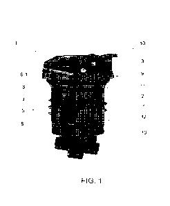
[18] Figure 1 illustrates a cut view where it is possible to visualize
all the main constructive details of the flow control device of the present
invention; and
[19] Figure 2 illustrates the flow control device in a perspective
view.
DETAILED DESCRIPTION OF THE DRAWINGS
[20] As can be seen in figure 1, the flow control device 1 for in-
serting into container openings of the present invention has a substan-
tially cylindrical outer format, suitable for inserting into container open-
ings, more specifically in openings of bottles. The flow control device 1
comprises a body 2, of substantially cylindrical and hollow configuration,
on whose outer wall there is a section endowed with thread 8. The thread
profile is preferably formed seamlessly with the very body 2 of the de-
vice, and is the element responsible for threading the body 2 of the de-
vice onto the opening of the bottle, which presents a corresponding inner
thread. Accordingly, the flow control device 1 operates fastened to the
opening of the bottle, without the need to remove it to pour the liquid out
of the bottle into another container. The specific sizes of the body 2 (for
CA 03239045 2024- 5- 23
5
example, diameter and thickness of the wall) and of the thread are de-
sign parameters which should be sized in accordance with the associ-
ated container. For example, the outer diameter of the body 2 should be
designed such that it enters into the opening of the container (for exam-
ple, a bottle), in order to be threaded thereon. The material is preferably
polymer, particularly polypropylene, though a person skilled in the art will
perceive that other materials are suitable for embodying the device.
[21] The flow control device 1 of the present invention further com-
prises a drive assembly 3, which is configured to restrict or allow the flow
passage of the container to the inside of the device. In normal state, that
is, when free of drive, the drive assembly 3 blocks the passage of the
liquid from the container to the inside of the flow control device 1. This is
possible because the drive assembly 3 comprises a valve set 9, which
comprises a valve element 12 and at least one gasket 13 arranged at
the base of the valve element 12. The gasket 13 at the base of the valve
element 12 is in sealing contact with the base of the body 2 of the device
1, such that no liquid reaches the inside of the device even when the
container is poured.
[22] The drive assembly 3 further comprises a drive mechanism
which should be configured such that it enables easy access and
handling by the user's hands, preferably arranged on the top part of the
flow control device 1. The drive assembly 3 comprises at least one pin,
preferably two pins, and a drive element, preferably a lever or a button.
A person skilled in the art will easily perceive that other options of drive
elements are possible. Lastly, the drive assembly 3 further comprises an
elastic element 11, preferably a spring, which is arranged concentrically
around a portion of the valve set 9, preferably on its top portion.
[23] Upon actuation of the user on the drive element, for example,
in pressing the lever or the button, the drive element will promote the
CA 03239045 2024- 5- 23
6
longitudinal displacement of the valve set 9 so as to cease contact be-
tween the base of the valve set 9 and the bottom part of the body 2 of
the flow control device 1. At the same time, the elastic element 11 is
pressed. In the driven state of the drive assembly 3, therefore, when the
user pours the container, the liquid may flow to the inside of the flow
control device 1 through the space formed between the base of the valve
set 9 and the body 2. To block the passage of liquid to the inside of the
flow control device 1 once again, the user merely has to return the drive
element to its original state. The elastic element 11, which was previ-
ously pressed, will assist the valve set 9 return to its initial
configuration,
the passage of liquid being blocked again.
[24] In the preferred embodiment of the present invention, there-
fore, the drive mechanism 10 is located at the top part of the flow control
device 1, above the body 2, and the valve set 9 extends inside the body
2 across its entire length, with its base resting in contact with the bottom
end of the body 2. The drive assembly 3 may also comprise other gas-
kets, for example, around the axis of the valve set 9, to confer better
overall sealing.
[25] The body 2 of the flow control device 1 of the present inven-
tion houses on its inside a fluid passageway arrangement 4, whose in-
ternal cavity forms the path that the liquid will take from its entry into the
flow control device 1, through its bottom end, to the exit thereof to the
outside environment. Therefore, is a fluid passageway arrangement 4
the element responsible for communicating the inside of the flow control
device 1 with the external pressure.
[26] The geometry of the internal cavity of the fluid passageway
arrangement 4 of the present invention is of the utmost importance, as it
is this that will essentially define the regime of flow of the jet of liquid
that
will leave the flow control device 1 when the container is poured. For
improved explanation of this geometry, it has been schematically divided
CA 03239045 2024- 5- 23
7
into two stages: a pressure equalization chamber 5 and an output duct
6, both contiguous to each other.
[27] The pressure equalization chamber 5 is the first stage of the
fluid passageway arrangement 4 that the liquid takes. The pressure
equalization chamber 5 has a larger cross section than the output duct
6, as can be ascertained in the preferred embodiment illustrated in figure
1. The geometry of the pressure equalization chamber 5 is designed
such that the liquid originating from inside the container accumulates
there before flowing to the output duct 6. It was verified by way of various
tests that this small permanence interval of the flow of liquid in the pres-
sure equalization chamber 5 enables pressure homogenization thereof,
which stabilizes the flow and impresses better pressure homogenization.
[28] After the pressure equalization chamber 5, there is an inter-
mediary transition phase of decreasing cross section which flows into
the output duct 6. The output duct 6 has a circular cross section, which
is also of the utmost importance for the jet of liquid leaving the opening
of the flow control device 1 to be stable, laminar and directional. In the
preferred embodiment illustrated in figure 1, the output duct 6 presents
a 90-degree curve to direct the flow to the outer opening of the flow con-
trol device 1, from where the liquid will be expelled. However, a person
skilled in the art will perceive that different possibilities of angulations
and curves are entirely possible, provided that due regard is given to the
circular cross section characteristic of the output duct 6.
[29] After the curve mentioned previously, the output duct 6 pref-
erably further presents a conical section 6.1 which extends, preferably,
to the terminal end of the output duct 6, the end wherethrough the fluid
will be expelled. The diameter of the cross section of the conical section
6.1 decreases towards this end, such that the flow of fluid is "tapered" as
it runs through the conical section 6.1, before finally being expelled. This
conical section 6.1 brings the effect of favoring the tapering, directioning
CA 03239045 2024- 5- 23
8
and lamination of the fluid in the act of pouring, thus being an additional
element contributing to stabilize the pouring of the liquid. In the preferred
embodiment illustrated in figure 1, the output duct 6 presents a small
cylindrical section, that is, having a circular and constant cross section,
after the 90-degree curve. In this embodiment, the conical section 6.1
begins after this small cylindrical section, extending to the exit end. How-
ever, a person skilled in the art will easily perceive that other configura-
tions are entirely possible, such as, for example, the start of the conical
section just after the 90-degree (or any other angle) curve. The length
and diameters of the conical section 6.1 may, therefore, be adapted in
accordance with the specific project specifications. Additionally, in the
preferred configuration illustrated, the conical section 6.1 is a separate
piece to be encased contiguously to the output duct 6. However, an al-
ternative configuration wherein the conical section 6.1 is a seamless part
of the output duct 6 (and, therefore, of the fluid passageway arrangement
4) is also entirely possible.
[30] Lastly, a final element of the fluid passageway arrangement
4 is the vent tube 7, which is located diametrically opposite the pressure
equalization chamber 5 and the output duct 6. In the preferred embodi-
ment illustrated in figure 1, the internal cavity of the fluid passageway
arrangement 4 which represents the output duct 6 is contiguous to an
internal cavity executed in the body 2, such that a section of the vent
tube 7 is located in the body 2 and the other section is located in the fluid
passageway arrangement 4, both having a circular cross section and the
same diameter.
[31] It is precisely these internal cavities of the fluid passageway
arrangement 4 ¨ which form the pressure equalization chamber 5, the
output duct 6 and the vent tube 7, besides the tapering of the liquid flow
promoted by the conical section 6.1, that are responsible for the regime
of liquid flow that leaves the flow control device 1. With this combination,
CA 03239045 2024- 5- 23
9
a laminar, stable and splash-free jet of liquid is achieved, enabling the
user to obtain greater precision in filling containers (glasses, cups, cala-
bash gourd, etc.) avoiding the disadvantages found in other conventional
metering stoppers. The harmonious combination of these elements
mentioned, besides the gap formed between the valve set 9 and the
body 2 of the flow control device 1, promotes an advantageous laminar
and directional control of the flow.
[32] The fluid passageway arrangement 4 is preferably manufac-
tured from the same material as the body 2 of the flow control device 1
and is encased in its internal cavity, so as to be retained therein after
assembling the flow control device I. In the preferred embodiment illus-
trated in figure 1, the body 2 and the fluid passageway arrangement 4
are two different elements which may be associated to each other, ena-
bling, among other things, the removal of the fluid passageway arrange-
ment 4, for example, for purposes of cleaning same and the inside of the
body 2. However, a person skilled in the art will perceive that it is possi-
ble to manufacture both elements cited in a seamless manner, without
impacting the scope of protection of the invention.
[33] Figure 2 enables improved visualization of the outer charac-
teristics of the flow control device 1 of the present invention. The sub-
stantially cylindrical shape of the flow control device 1 can be better un-
derstood here, being suitable for inserting into container openings, more
specifically in thermos bottles. It is worth emphasizing that the thread of
the section endowed with thread 8 is not illustrated in this view solely for
purposes of improved visualization of the device.
[34] The description set out above illustrates possible embodi-
ments of the present invention, though the scope thereof is not limited
by the examples expounded, nor by the drawings accompanying the ap-
plication. A person skilled in the art will perceive that various other con-
figurations are entirely possible.
CA 03239045 2024- 5- 23