Note : Les descriptions sont présentées dans la langue officielle dans laquelle elles ont été soumises.
~3~L3~
PHN 11 721 I 28-1-19~7
"Electric lamp having a mirror-coated lamp vesc3el".
The invention relates to an electric lamp com-
prising:
- a blown glass lamp vessel sealed in a vacuum-tight
manner and having a largest diameter, a translucent
wall portion and ~ wall portion which is mirror-coated
on its inner surface with an aluminium layer, this
mirror coated wall portion having a boundary near the
largest diameter of the lamp vessel;
- a light source arranged in the lamp vessel;
I0 ~ current supply conductors extending through the wall
~f the lamp vessel to the light source.
Such a lamp is known from European Patent Specification
0 022 304 (PHN.9536).
Lamps of the kind described in the aforementioned
European Patent Specification are manufactured by
evaporating aluminium in the lamp vessel at a reduced
pressure. For this purpose, a filament carrying a piece
of aluminium is temporarily arranged in the lamp vessel.
By current passage through this filament the aluminium
is heated and evaporated. ~nless this source of aluminium
vapour is screened in part, substantially the whole lamp
vessel is mirror-coated with a layer of aluminium.
Wall portions that would have had to remain;
without~a mirror-coating, can be freed from their
25~ aluminium layer in that they are brought into contact with
lyeO A sharp transition can then be obtained between wall
portions that are mirror-coated and wall portions that
are not mirror-coated. However, disadvantages of this
manufacturing method are that the lye has to be completely
removed by carefully washing the lamp vessel, that the
lamp vessel has to be dried thoroughly, that the lye
and the washing water used have to be made harmless for
the environment and that there is a risk of the reflective
,, .. - :
~63~L3~
PHN 11 7~1 -2~ 28-1-19~7
layer be:irlg damacJed by spatters of lye or washincJ-water.
Because of these dl~advan-tages of the partial
removal of a reflective coating, it is very at-tractive
to be able to apply a reflective layer only at the areas
at which it is desirable. The wall portion not to be coated
could be covered with a mask. In most cases, however, this
requires a mask which is larger than an openlng in the
lamp vessel (its neck), through which this mask has to be
introduced. It has been suggested to use foldable masks
o which are expanded within the lamp vessel, but such masks
are complicated and expensive. They have a short life be~use
they soon cannot be fully expanded or folded any longer
due to the fact that aluminium is deposited on them.
A simple and suitable method of partly mirror-
coating a lamp vessel consists in that a screen is providedclose to the vapour source, as a result of which a part of
the wall of the lamp vessel lies in the shadow of this
screen during evaporation of the aluminium. However, this
method has the disadvantage that a part of the ~all of
the lamp vessel lies in a half-shadow. The lamp manufactured
by this method has the disadvantage that a very thin alumi-
lnium layer has formed on the wall of the lamp vessel dur-
ing evaporation at the area of the half-shadow. This
very thin translucent aluminium layer becomes manifest
as a black zone which adjoins the mirror-coated wall
portion at the area at which the screen would have had to
prevent deposition of aluminium near the largest diameter
of the lamp vessel.
The said half-shadow is caused by the fact that
the vapour source is not infinitely small, but in view
of the surface to be covered has a certain minimum volume.
The half-shadow is also caused by the fact that aluminium
vapour is exposed to the scattering effect of the residual
gas in the lamp vessel on its way from the vapour source
to the wall of the lamp vessel. The mirror-coating step
is effected at reduced pressure, for example at 0.1 to
0.01 Pa, because an unacceptably long processing period
would be involved in producing a high vacuum.
.
- ~ .
.
.~
; ` ~ ' ; !
} ~ , ' ,
3~
Pl-IN 11 721 3- 2~ 1987
The dark zone limlting in the ~nown la~np the
mirror-coated wall portion is disadvantageous. 'rhe zone
causes the lamp to have an unaestl1etic appearance and h-s
an adverse effect on its quality impression.
The zone does not reflect incident light from the light
source efficiently, but does not transmit that light sub-
stantially completely either.
The invention has for its object to provide a
lamp of the ]cind described, which can be readily manu-
factured and in which nevertheless the effect of the saidhalf-shadow is counteracted.
According to the invention, this object is achieved
in an electric lamp of the kind mentioned in the opening
paragraph in that the inner surface of the lamp vessel has a
zone which is coated with a transparent aluminium oxide
layer and adjoins the boundary of the mirror-coated wall
portion near the largest diameter of the lamp vessel.
It has surprisingly proved to be possible to
remove the dark zone limiting ~ mirror-coated wall portion
which is obtained by evaporation of aluminium with the
use of a screen near the vapour source. This dark zone can
moreover be removed very rapidly and a very sharp
boundary (without a meander) of the mirror-coated wall
portion can be the result. It has been found that, when
the dark zone is heated in air for a short time, a convers-
ion of aluminium into aluminium oxide is obtained J which
adjoins the mirror-coated wall portion as a hardly visible
whitish haze. Further, a part of the aluminium evaporates.
The heat treatment may be carried out by means
of a burner having a sharply defined flame, but may
alternatively he carried out by means of a laser, for
example, a neodymium-doped yttrium-aluminium-garnet laser.
The lamp vessel may be rotated about an axis at right
angles to the boundary of the mirror-coated wall portion
along the front of the heat source. A lamp vessel can thus
be treated in a very short time, for example 1 second.
The use of such a laser has the additional advantage that
its heat is substantially not absorbed by the glass of the
' ,: ;'', .:
~;21E;3~L,3~
PIIN 11 721 -4- 28-1-1987
lamp vessel. Thus, stresses are preventecl from being
produced ln the ylass. If the heat source, ~or example a
burner, heats the glass of the lamp vessel above its lowest
transition temperature, l.e. in the case of lamp glass
ahout 495C, it is recommendable to eliminate stresses in
the glass by gradually cooling the glass. In general,
however, stresses can be prevented ~rom being bui].t up in
the glass hy keeping the temperature just below the lowest
transition temperature.
Upon accurate observation, the zone with the
aluminium oxide layer is visible on a transparent wall
portion as a whitish haze. The latter does not adversely
affect the appearance of the lamp. However, the aluminium
oxide layer can be clearly observed by means of Auger
Electron Spectroscopy (AES3.
The zone with the aluminium oxide layer (Z) was
examined by means of AES (t = 0) with respect to the
presence of Al, 0 and Si. After the measurement, there
was sputtered with Ar ions for 1 minute and measured
again (t = 1). A third measurement was carried out after
sputtering for another 1 minute (t = 2). The same
e~amination was carried out on the mirror-coated wall
portion (M) and on the wall of another lamp vessel at the
area at which an aluminium layer was removed by etching
with lye (E). The results are indicated in Table 1.
Table 1
t (min),0 (at%) Al (at%) ~Si (at%) ~ ~
57 43 n.d
0 M 65 35 n.d.
E 65 _ 33
Z 58 36 6
1 M 2 65 98 1 n.d
_ .
Z ~8 ~4 18
2 M 1 9~ n.d
E 65 n.d. 35
n.d. = not detectable
i3~7
PHN 11 721 -5- 2~ 1987
:t-t appears therefrom that the mirror (M) consis~s
at its surEace (t = 0) of aluminium oxide and a-t areas
locatecl more deepl~ (t = I; 2) oE aluminium me-tal. A
wall portion which is freed from an aluminium layer by
etching (E) has at its surface (t = O) a very small quantity
(2 at.%) of aluminium in oxidic form; below this surface
this quantity is halved (t = 1) and nihil (t - 2), respecti-
vely. The æone of the lamp according to the invention (Z)
on the contrary consists at the surface (t = O) completely
of aluminium oxide (no silicon is found). Below the surface
the content of silicon increases (t = 1; 2). Also at this
area the aluminium present is in the oxidic form, as was
also apparent from the signal of a spectrometer.
The film of aluminium oxide, which is at the
surface substantially free from silicon, is characteristic
of the zone in the lamp according to the invQntion, in
contrast with a glass surface of a wall portion freed from
a reflective aluminium layer by etching, this glass surface
having very small residues of oxidic aluminium.
The electric lamp according to the invention may
have as a light source a filament or a pair of electrodes
in an ionizable gas.
The mirror-coated wall portion may have different
forms, such as the form of a ring in the case of a reflector
lamp and substantially the form of a hemisphere in the
case of a bowl mirror lamp.
~; Embodiments of the lamp according to the invention
are shown in the drawing. The drawiny shows, partly broken
away:
in Fig. 1 a bowl mirror lamp in side elevation,
in Fig. 2 a ring mirror lamp in side elevation.
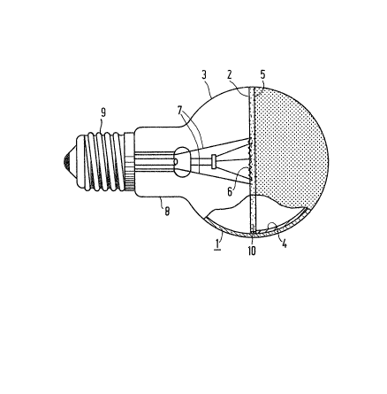
In Fig. 1, the bowl mirror lamp comprises a blown
glass lamp vessel 1 sealed in a vacuum-tight manner and
having a largest diameter 2, a transparent wall portion 3
and a wall portion 4 which is mirror-coated on i~s inner
surface wit.h an aluminium layer and has a boundary 5
near the largest diameter 2 of the lamp vesseI 1. A
filament 6 is arranged as a light source ln the lamp vessel
: `
'' r
~6~
P~IN 11 721 ~ ~6 28~ 19~7
I and cur:rent supply conductors 7 e~tend through the wall
of the lamp vessel 1 to this fllament 6. The larnp vessel
has a neck-shaped wall por-tion 8 at the area at which the
lamp vessel 1 is sealed, this wall portion carrying a lamp
cap 9. The inner surface of the lamp vessel 1 has a zone
10 which is coated with a transparent aluminium oxide layer
and which adjoins the boundary 5 of the mirror-coatecl wall
portion 4 near the largest diameter 2 of the lamp vessel 1.
In Fig t 2, corresponding parts are designated
by a reference numeral which is 10 h.igher than in Fig. 1.
In this Figure, the mirror-coated wall portion 1~ is
annular and has a second boundary 21 located in the neck-
shaped wall portion 18. This boundary 21 is adjoined by
a zone 22 which has an aluminium layer of only small
thickness, as a result of which it has a dark appearance.
The zone 22 is of little importance because a reflective
layer in this zone is of no importance for the concentration
of light and because in this zone no useful light could
emanate even in case the coating was absent~
Furthermore, this zone is not disturbing because t.he
part of the lamp in which this zone is located is generally
situated during operation within a luminaire or lamp
holder.
In contrast to the transparent wall portion 13,
which has a diameter larger than that of the neck~shaped
: wall portion 18, the zone 22 and the remaining part of
the nec~-shaped wall portion 18 facing the lamp cap 19
can readily be screened by a mask from the vapour source
during the application of the aluminium layer. During the
application of the aluminium layer, the neck-shaped wall
portion 18 then does not yet exhibit a narrowed part near
the lamp cap 19, as shown in the Figure, but is widened at
this area so that, i desired, a mask of the desired size
may readily be introduced.
If desired, however, the zone 22 may also be
thermally convert~d into a zone with a transparent
aluminium oxide layer.
The bowl mirror lamp of Fig. 1 may also have an
.
. : . . . . .
: ~ . . : .- . .
~2~;3~
P~-IN 11 721 -7 28~1-1987
annul~r mirror-coated wall portlon iE a. ligh-t w:i.ndow ls
present opposite to the lamp cap 9. A similar zone with a
transparent aluminium coating may be present at the boundary
be-tween the mirror-coated wall por-tion and t~iis window.
: :
; 30
: :
:
, ;,, - :
. . - .: . :
, . . : :: :. : -
,.~ , -