Note : Les descriptions sont présentées dans la langue officielle dans laquelle elles ont été soumises.
~.~7~7~C~
The present invention relates to armchairs,
particularly for use in the open air, in which
the footrest, pivotally borne by the front edge
of the seat, is connected to the backrest articu-
lated on the legs, so that any modification ofthe inclination of the backrest brings about a
corresponding modification of that of the footrest.
It is an object of the invention to produce
an armchair of the type set forth hereinabove
10 which, whilst being of simple and ~obust construc-
tion, is capable of being folded into small dimen-
sions for transport, storage or stowing thereof.
The armchair of the invention is essentially
noteworthy in that the rear end of each of the
15 longitudinal connecting elements which, in conven-
tional manner, connect the backrest and the foot-
rest, is articulated on a pivoting crank pin which
is angularly connected to said backres-t only in
one direction of rotation so as to remain free
20 to pivot in the opposite direction when the whole
of the seat is folded.
The invention will be more readily understood
on reading the following description with reference
to the accompanying drawings, in which:
~ig. 1 is a side view of an armchair accor
ding to the invention, shown in the position where
its backrest is most upright.
Fiy. 2 reproduces Fig. 1, in the most in-
clined position of the backrest.
Fiy. 3 is a view in elevation of the armchair
from the rear.
Fig. 4 is a view in perspective, on a larger
scale, showing the rear part of the arrnchair at
the level of the articulated connection provided
between the backrest and the seat.
$~
7 ~
~ J. 5 is a side view similar to tl~ose
oL ligs. 1 and 2, but sllowing the armcllair being
folded.
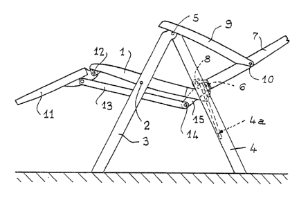
ReEerring now to the drawings, reference
L desiynates the seat of the armchair of whicl~
t~le edges are articulated at 2 on the front legs
3 pivotally assembled at 5 on the rear legs 4
in order to deEine a Eoldable support forrned by
two braced lateral legs in tlle Eorm oE a downwardly
10 oL~en V. On the rear, narrowed part of the seat
1 is articulated at 6 (cE. Fig. ~), the base of
tl)e inclinable backrest 7 which is supported by
e rear legs ~ by means of two projectiny pins
~ (sllown in Fiy. 4 in tl~e form of simple lines
15 of axis) slidably engaged in slideways 4a. The
latter are made longitudinally in the inner wall
Or tl~e rear legs 4, each slideway 4a presenking
at its upper end a transverse step for retaining
the corresponding yin 8 and for holding the seat
20 1 in substantially llorizontal position, whilst
a]lowing the armcllair to be folded.
Adjustment of the inclination oE the backrest
7 and immobilizatîol- thereoE at the chosen inclina-
tion are effected by means oE two armrests 9 articu-
25 lated at 10 on said backrest 7. Tlle downwardly
turlled face oE each armrest 9 comprises a rack
toothiny adapted to cooperate selectively with
a fixed tooth provided Oll one or the other of
tlle legs 3 or 4, above the pivot 5 thereof.
This arrangement is well known in practice
and, in addition, has been described in detail
in ~pplicant's French Patent No. 2,596,261.
The armchair also comprises a Eootrest
35 11 pivotally borne at 12 by the Eront edge of
--3--
the seat 1. Two longitudinal connecting elements13 connect -this Eoo-trest 11 to the backrest 7
so that any modification oE the inclination of
the latter causes tipping of said footres~ which,
5 in the most upright position of the backrest (Fig.
1~, is folded ver~ically beneath the seat 1,
whilst, in the inclined position of Fig. 2, it
is raised in line with this seat. The connecting
elements 13 must, in addition, make it possible
10 to fold the whole of the armchair to reduced dimen-
sions (cf. Fig. 5), with the footrest 11 brought
parallel to the seat 1.
To this end and as shown more particularly
in Figs. 3 and 4, the rear end of each connecting
15 element 13, connected to the opposite connecting
element by a crosspiece 13a, is pivotally assembled
at 14 on a crank pin 15 which, in the embodiment
envisaged, traverses a slot la in the seat 1 to
articulate on the corresponding pivot 6, between
20 the two lugs lb of said seat which bear this pivot.
Each crank pin 15 is sectioned to present a support
or bearing face lSa adapted to cooperate with
an upper stop 7a provided on the backrest 7.
In order to explain operation of the arm-
25 chair, the upright position illustrated in Fig.
1 will be the starting point. It will be understood
that~ when, by suitably manoeuvring the immobili-
zing armrests 9, the user wishes to bring the
armchair into the inclined position oE Fig. 2
30 or to an intermediate position, rearward pivoting
oE the backrest 7 causes, by action of the stops
7a against the bearing faces 15a, actuation of
the connecting elements 13 which therefore progres-
sively raise the footrest 11.
When, on the other hand, it is desired
~.~7~'7~
to return the armchair from the inclined position
of Fig. 2 to the upright position oE Fig. 1 or
to any intermediate position, there is obviously
no more positive action of the backrest 7 on the
5 connecting elements 13, but the bearing faces
15a remain in contact with the stops 7a due to
the weight in overhang o~ the footrest 11 which
is exerted on the connecting elements 13. The
footrest 11 therefore follows, to some extent,
10 by progressive downward folding, the straightening
up of the backrest 7.
The unidirectional angular connection exis-
ting between the crank pins 15 and the backrest
7 and consequently between the latter and -the
15 footrest 11, further allows the armchair to be
folded in the manner illustrated in Fig. 5. In
fact, during such folding, the crank pins 15,
until then oriented substantially in line with
the backrest 7, are free to pivot (angle ~ )
to be oriented substantially perpendicularly to
the seat 1 and to the backrest 7, thus allowing
the connecting elements 13 to move back and the
footres-t 11 to fold down completely, the latter
consequently being oriented parallel to the other
elements of the armchair.
The construction according to the invention
and use thereof are much s.impliEied with respect
to the known arrangements which most often employ
telescopic or sliding systems provided with a
manual locking mechanism. The system according
to the invention is totally reliable.
It will be understood that the assembly
of the crank pins 15 and actuation thereof by
the backrest 7 in one direction of pivoting may
differ from those envisaged hereinabove, as long
47~
as a unidirectional angular connection is obtalned.
It must, moreover, be understood tha-t the
foregoing description has been given only by way
of example and that it in no way limits the domain
of the invention which would not be exceeded by
replacing the details of execution described by
any other equivalents.