Note : Les descriptions sont présentées dans la langue officielle dans laquelle elles ont été soumises.
753L~i5
BACRBROUND OF THE INVENTION
1. Field of the Invention:
The pre~ent invention relates to a hook for a
hook-and-eye fastener for fastening two pieces of a
garment such as a trouser or a skirt.
2. Pxior Art:
Known hooks for hook-and-eye ~a~teners generally
include a hook body having a plurality of prongs on a hook
base that penetrate a garment fabric and have bent end
portions retained on a retainer for attaching the hook to
the garment fabric. The hook body further has a locking
tongue lying substantially parallel to the base and an
intermediate bent portion extending between the base and
the locking tongue. This hook body iæ relatively weak and
hence is likely to be crushed or permanently deformed at
the bent portion when subjected to a force tending to
- compress the base and the locking tongue during, for
instance, the ironing of the garment fabric. With the hook
body thus cruæhed, a ~mooth insertion of the locking tongue
into the companion loop or eye is difficult to achieve.
One attempt made heretofore to overcome the
foregoing drawback is disclosed in Briti 8 h Patent No.
821549, wherein a hook body has a plurality of elongated
reinforcing ribs projecting on the outer surface of the
hook body and extending from a base through a bent portion
to a locking tongue, there being defined in the inner
surface of the hook body a correspond~ng number of grooves
complementary in contour to ths projections. The disclosed
hook body having such outwardly projecting ribs is
defective from an ae~thetic view and rough to touch.
Further, sinc~ the ribs and the grooves are formed by
stamping, the hook body is lik~ly to be damaged or broken
at the bent portion due to cracks oreated during tha
famation of the ribs and grooves.
-- 2
~75~L6S
SUMMARY OF ~HE INVENTION
It is therefore an objeot of the present
invention to provide a hook for a hook-and-eye fastener
which is strong enough to withstand forces tending to crush
-S or permanently deform the hook at an arcuately bent
portion thereof.
Another ob;ect of the present invention is to
provide a hook for a hook-and-eye fastsner which is
sightly in appearance and smooth to touch.
According to the invention, a hook for a
hook-and-eye fastener includes a one piece hook body having
a locking tongue and a base underlying the locking tongue,
and an arcuate portion joining the locking tongue and the
base, the base having a pair of prongs projecting
substantially perpendicularly therefrom in a direction away
from the locking tongue. The hook body has a plurality of
cold-pressed elongated recesæes extending from the base
through the arcuate portion to the locking tongue, thereby
giving resilience and strength that are large enough to
withstand forces tending to permanently deform the hook
body at the arcuate portion. ~he recesses are defined in
an inner surface of the hook body which is concealed from
the view 80 that the hook body iB sightly in appearance and
smooth to touch. The hook alRo includes a retainer having a
pair of openinys through which prongs on the base extend.
The openings are ~paced from each other by a distance which
is greater than the distance between the prongs. Each of
the prongs has a bent end portion retained on the retainer
with a space defined therebetween. Nith the hook thus
constructed, the hook body is tiltable with respect to the
retainer, thereby accommodating the thrust applied thereto
during, for instance, the ironing of a garment fabric to
which the hook is attached.
Many other advantages and features of the present
invention will become manifest to those versed in the art
-- 3 --
~.~75~65
upon making reference to the deta:Lled description and the
accompanying sheets of drawings ln which a preferred
structural embodiment incorporating the principles of the
present invention i~ shown by way of illu~trative example.
BRI EF DESCRI PTI ON OF THE DRAWI NGS
FIG. 1 is a front elevational view of a hook body
of a hook according to the present invention;
FIG. 2 is a plan view of the hook body shown in
FIG. 1.
FIG. 3 iB a bottom view of FIG. 2;
FIG. 4 is a right siae elevational view of the
hook body;
FIG. 5 is a cross-sectlonal view taken along line
V - V of FI G. 2;
FIG. 6 is a plan view of a retainer of the hook
according to the present invention;
- FIG. 7 iS a bottom view of FIG. 6;
FIG. 8 is a cross-seotional view taken along
line VIII - VIII of FIG. 6
FIG. 9 iS a front elevational view, partly in
cross section, of an assembled hook; and
FI G. 10 i s a cross-s ectional view taken along
line X - X of FIG. 9.
DE~AILED DESCRIPTION
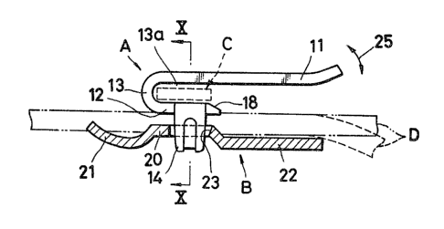
FIGS. 1 through 5 show a hook body A of a hook
for a hook-and-eye fastener for fastening two pieces of a
garment. ~he hook body A is pres6 formed from a sheet metal
and includes an upper locking tongue 11, a lower bass 12
lying substantially parallel to the locking tongue 11, and
an intermediate arcuate portion 13 extending between the
locking tongue 11 and the base 12 for defining
therebetween an eye-receeiving channel 13a for receiving a
- portion of the companion loop or eye of the hook-and-eye
fa~tener. A pair of prongs 14, 14 is disposed on opposite
edges of the base 12 and projects substantially
-- 4
.~ ,
'7S~
perpendicularly therefrom in a direotion away from the
locking tongue 11.
The hook body A further has a plurality of
elongated recesses 15 (three in the illustrated embodiment)
formed by cold pre~sing and extending from the base 12
through the arcuate portion 13 to the locking tongue 11.
The cold-pressed elongated recssses 15 are defined in an
inner surface of the hook body A faclng the eye-receiving
channel 13a. A6 best ~hown in FIG. 5, each of the recesses
15 has opposite end portions progres6ively reducing in
depth and terminating in a plane in which the longitudinal
central axes 16 of the prongs 14 extend. The hook body A is
thus of a high cold pressed modulus in a region ad~acent
the elongated recesses 15 for facilltating the bending of
the blank of the hook body and at the ~ame time affording
increased resilienca and 6trength to the arcuate portion
l_ 13. Since the recesses 15 are formed by cold pressing, the
¦ hook body A is free from crack6 which would be created in a
comparative prior hook body having ~tamped ribs. The number
of the ~rooves 15 i~ not limited to three in the
illustrated embodiment. Further, outer surface of the hook
body 25 is neither ribbed nor grooved so that the hook body
A as a whole is slightly in appearance and smooth to touch.
As shown in FIG. 1, the prongs 14 are located
such that the longitudinal central axes 16 of the prong
14 extend in a plane which is spaced from the vertex of the
*arcuate portion by a distanca ll substantially equal to
one-fourth of the entire length l2 of the hook body A, the
length 12 corresponding to the di~tance between the vertex
of the arcuate portion 13 and tha free and of the locking
tongue 11. Each of tha prongs 14 has in its outer side
6urface an elongated recess 17 formed by cold pressing and
extending along the longitudinal aentral axi6 16 of the
prong 14 so that a region ad~acent the recess 17 is harder
than the other region of the prong 14. Although not shown,
5 _
. .
.,
S~
the base 12 may have an additiona:L prong located at one of
the free end or the proximal and of the base 12.
The free end of the base 12 has a sloped guide
surface 18 facing away from the arcuate portion 13 to
provide a wide entrance for the companion eye to be
introduced into the eye-reoessing channel 13a. In the
illustrated embodiment, the sloped guide surface 18 is
formed by chamfering the free end of the base 12. Such
guide surface may be formed by bending the free end of the
base 12 in a direction away from the locking tongue 1. The
locking tongue 11 projects beyond the free end of the base
12 by a distance 14 which is one and half times to two
times as large as the distance 13 between the vertex of ths
arcuate portion 13 and the free end of the ba~e 12.
~s shown in FIGS. 6 - 8, an oblong retainar B is
press-formed from a sheet metal and includes a central
raised portion 20 extending throughout the width of the
retainer 20, an upwardly bent rear portion 21 extending
rearwardly from the central raised portion 20, and a flat
front portion 22 extending forwardly from the central
raised portion 20. As shown in FIG. 8, ths bent rear
portion 21 has a bottom surface lying flush with the
bottom surface of the flat front portion 22, and a free end
lying flush with the top surface of the central raised
portion 20.
The retainer has a pair of transversely spaced
rectangular openings 23, 23 defined in the central raised
portion 20 for receiving the prong 14, 14, respectively.
The openings 23, 23 are spaced from one another by a
distance Ll (FIG. 6) which is smaller than the distance 15
~FIG. 4) between the prongs 14, 14. Each of the rectangular
openings 23 has a width or an extent L2 (FIG. 6) in the
longitudinal direction of the retainer B, which extent L2
is greater than the width 16 (FIG. 1) of the prongs 14.
Further, the free end of the flat front poxtion 22 is
-- 6 --
,
i5
spaced from a central line of the openings 23 by a di6tance
L3 (FIG. 6) which is smaller than the di~tance 17 (FIG. 1)
between the free end of the locking tongue 11 and the plane
in which the longitudinal central axes 16 of the prongs 14,
14 lie.
The hook body A and the retainer ~ are assembled
together into a clinched condition as shown in FIGS. 9 and
10 For assembling, the pronys 14, 14 of the hook body A
penetrate a garment fabric D and extend through the
openings 23, 23 in the retainer B. Then, end portions of
the prongs 14 are deformed by a punch-and~die unit (not
shown) into inwardly axial].y bent ends until respective
distal ends engage the retainer B with spaces 24 (FIG. 10)
defined between tha bent end portions and the retainer B.
The hook body A and the retainer B thus attached together
with the garment fabric D dispo~ed therebetween, constitute
a hook engageable with a loop or eye C (FIG. 9) attached
to anothsr garment fabric, not shown. In this assembled
condition, the free end of the upwardly bent rear portion
21 and the central raised portion 2V bite into the garment
fabric D to prevent the relative movement between the
retainer B and the garment fabric D. Partly because of the
distance 15 (FIG. 4) greater than the distance Ll (FIG.
6), and partly because of the clearances 24, the hook body
A is tiltable about the distal ends of the prongs 14 in the
directions indicated by the arrowheads 25 in FIG. 9.
Furthermore, since the width L2 of the openings 23 is
greater than the width of the prsngs 14, the hook body A is
movable in a plane parallel to the retainer B. Such
relative movement between the hook body A and the retainer
and the incraased resiliency and strength of tha arcuate
portion 13 jointly serve to take up or accommodate forces
tending to depress the locking tongue 11 toward the
retainer B, thereby preventing the hook body ~ from being
crashed ox permanently deformed at the arcuate portion 13.
-- 7 --
,,
( ~
S~;5
Another advantage of the hook lies in that the
prongs 14 are located near the arcuate portion 13; the
distance 11 between the vertex of the arcuate portion 13
and the axes 16 of the prongs 14 approximately e~ual to
one-fourth of the entire length 12 of the hook body A. The
smallness of the dlstance 11 enables the upwardly bent rear
portion 21 to be reduced in length, providing a large area
for sewing threads running along edges of the garment
fabric D. Furthermore, the locking tongue 11 projects
beyond the distal end of the flat front portion 22 of the
retainer B so that a relatively large entrance to the
eye-receiving channel 13a can be provided between the free
end of the locking tongue :L1 and the garment fabric D when
the latter is bent downwardly over the free end of the flat
front portion 22 as indicated by broken lines in FIG. 9.
Thus, when the hook body A and the eye C are brought into
interlocking engagement with each other, a portion of the
eye C can easily be introduced from such wide entrance into
a space between the locking tongue 11 and the garment
fabric D, and thence it is introduced into the
eye-receiving channel 13a. During that time, the sloped
guide surface 18 allows a smooth insertion of the portion
of the eye C into the channel 13a.
Although various minor modifications may be
suggested by those versed in the art, it should be
understood that we wish to embody within the scope of the
patent which may issue hereon, all uch embodiments as
reasonably and properly come within the scope of our
contribution to the art.