Sélection de la langue

Search

Sommaire du brevet 1284785 

Énoncé de désistement de responsabilité concernant l'information provenant de tiers

Une partie des informations de ce site Web a été fournie par des sources externes. Le gouvernement du Canada n'assume aucune responsabilité concernant la précision, l'actualité ou la fiabilité des informations fournies par les sources externes. Les utilisateurs qui désirent employer cette information devraient consulter directement la source des informations. Le contenu fourni par les sources externes n'est pas assujetti aux exigences sur les langues officielles, la protection des renseignements personnels et l'accessibilité.

Disponibilité de l'Abrégé et des Revendications

L'apparition de différences dans le texte et l'image des Revendications et de l'Abrégé dépend du moment auquel le document est publié. Les textes des Revendications et de l'Abrégé sont affichés :

  • lorsque la demande peut être examinée par le public;
  • lorsque le brevet est émis (délivrance).
(12) Brevet: (11) CA 1284785
(21) Numéro de la demande: 510993
(54) Titre français: CRIBLE MECANIQUE A DISPOSITIF REPARTITEUR-SEPARATEUR INTEGRE
(54) Titre anglais: SCREENING APPARATUS WITH INTEGRATED DISTRIBUTING AND SEGREGATING DEVICE
Statut: Réputé périmé
Données bibliographiques
(52) Classification canadienne des brevets (CCB):
  • 209/99
(51) Classification internationale des brevets (CIB):
  • B07B 1/46 (2006.01)
  • B07B 13/16 (2006.01)
(72) Inventeurs :
  • EGGERSTEDT, KARL HEINZ (Allemagne)
(73) Titulaires :
  • FREDRIK MOGENSEN AB (Suède)
(71) Demandeurs :
(74) Agent: GOWLING WLG (CANADA) LLP
(74) Co-agent:
(45) Délivré: 1991-06-11
(22) Date de dépôt: 1986-06-06
Licence disponible: S.O.
(25) Langue des documents déposés: Anglais

Traité de coopération en matière de brevets (PCT): Non

(30) Données de priorité de la demande:
Numéro de la demande Pays / territoire Date
P 35 20 614.4 Allemagne 1985-06-08

Abrégés

Abrégé anglais


ABSTRACT OF THE DISCLOSURE

A screening apparatus of the multi-deck type has the
feed inert space of the screening machine comprising one or
more distributing and segregating devices integrated with the
movement of the screening apparatus.

Revendications

Note : Les revendications sont présentées dans la langue officielle dans laquelle elles ont été soumises.


THE EMBODIMENTS OF THE INVENTION IN WHICH AN EXCLUSIVE
PROPERTY OR PRIVILEGE IS CLAIMED ARE DEFINED AS FOLLOWS:

1. A distributing and segregating device for a multideak
screening machine which includes a frame housing a plurality of
successive, superimposed screening decks, an inlet end through
which material to be screened can be fed onto an upstream end of
an upper deck, an outlet end having a plurality of outlets
associated with overflows or underflows of one or more succes-
sive ones of said screening decks, and at least one vibrator for
vibrating the frame, including said inlet end, for advancing
material received through said inlet end, across and through the
screening decks and to said outlets
said device comprising a module adapted to be
removably exchangeably supported on the frame of said multideck
screening machine for vibration therewith at said inlet end as a
means for feeding material to be screened into the multideck
screening machine through said inlet end, and including:
wall means defining an enclosed box having an upwardly
opening inlet and, transversally displaced from vertical
registry with said inlet, a forwardly and downwardly opening
outlet;
said wall means including a floor for said box, said
floor having a sloping, gabled, medially ridged upstream
portion disposed in vertical registry under said inlet and
sloping down towards a juncture with a sloping downstream
portion which is flatter by being less gabled and less medially
ridged than said upstream portion; said downstream portion
leading to said outlet at a downstream edge of said floor.
2. The distributing and segregating device of claim 1,
further including:
at least one distributing component mounted to said
wall means so as to have an elevated lower edge extending
transversally of said device at a location spaced above said
floor at a site disposed intermediate said inlet and said outlet
for encountering and adjusting excesses in height of material
being fed through said device to said multideck screening
machine.

-6-

3. The distributing and segregating device of claim 2,
wherein:
said lower edge of said distributing component is
serrated.
4. The distributing and segregating device of claim 2,
wherein:
said lower edge of said distributing component is
castellated.
5. The distributing and segregating device of claim 2,
further including:
at least two transversally neighboring deflectors
mounted to and disposed upon said downstream portion of said
floor for laterally deflecting material being fed over said
floor towards said outlet.
6. The distributing and segregating device of claim 5,
wherein:
said deflectors are movably mounted to said floor for
providing adjustable deflection of said material.
7. A distributing and segregating device for a multideck
screening machine which includes a frame housing a plurality of
successive, superimposed screening decks, an inlet end through
which material to be screened can be fed onto an upstream end of
an upper deck, an outlet end having a plurality of outlets
associated with overflows or underflows of one or more succes-
sive ones of said screening decks, and at least one vibrator for
vibrating the frame, including said inlet end, for advancing
material received through said inlet end, across and through the
screening decks and to said outlets
said device comprising a module adapted to be
removably exchangeably supported on the frame of said multideck
screening machine for vibration therewith at said inlet end as a
means for feeding material to be screened into the multideck
screening machine through said inlet end, and including:
wall means defining an enclosed box having an upwardly
opening inlet and, transversally displaced from vertical
registry with said inlet, a downwardly opening outlet;
said wall means including a floor for said box, said

-7-


floor being downwardly sloping, gabled, medially ridged, from
under said inlet to a downstream edge at said outlet;
said floor comprising two laterally adjacent flaps
which adjoin along a medial ridge; and
means for slope-adjustably mounting said flaps to said
box.
8. The distributing and segregating device of claim 7,
wherein:
as seen in top plan, said downstream edge of said
floor slants obliquely rearwardly in both lateral direction
from said medial ridge.
9. The distributing and segregating device of claim 8,
further including:
a respective weir-like guide member height-adjustably
secured to each said flap along said downstream edge of said
floor.
10. The distributing and segregating device of claim 7,
further including:
an upwardly domed element mounted between said wall
means in said box above said floor in vertical registry with
said inlet, so that material which is to be screened, upon being
introduced into said distributing and segregating device
through said inlet, encounters and is deflected by said domed
element before becoming supported on said floor.
11. The distributing and segregating device of claim 10,
wherein:
said domed element is disposed for deflecting some of
the material onto one of said flaps and some of the material
onto the other of said flaps.

-8-
Description

Note : Les descriptions sont présentées dans la langue officielle dans laquelle elles ont été soumises.


347~5
The invention concerns a screening apparatus ana is
particularly suitable to and intended for screening machines of
the multi-deck type.
sackqround of the Inyention
The manner in which granular materials are being fea to
a screen is of vital influence when it comes to aahieving optimum
capacity and efficiency.
Normally, screens are fed by means o.~ feeding equipment
such as conveyors, screws, vibratiny feeaers, etc. In such ~ase~
a more or less even ~istribution oP the material ~o be screened
is achieved prior to the screening apparatus. Often the material
will be fed straight on to the screen cloth or the screening
apparatus is equipped with a so called feeder plate onto which
the material is brought in order to protect the screen cloths
from wear. The material then falls from this feeder plate onto
the screen cloth.
This way of feeding has the consequence that the active
screening area is not optimally utilized, because certain areas
near the inlet are not engaged or the distribution of the
material across the width is uneven. Frequently, the bed of
material is thicker in the middle than near the sides so that the
centre would be overloaded while the outer parts of the screen
cloths could take more load.
Further, the material to be screened, whiah consists of
a mixture of fine and coarse particles, must be segregated in the
screening process so that the fine particles can be separated
from the coarser ones. This happens relatively slowly and the
relative capacities per screening surface area are corres-
pondingly small. As a consequence, screens have to be unneces-
sarily large.
The invention aims at avoiding the disadvantages aboveand solves the problem of obtaining screening apparatuses where
t:he material, upon arrival at the screen cloths, is evenly
distributed and also already to a certain extend segregated, so
that the screen cloths can be optimally used for their purpose
and the screening apparatuses can be made much smaller, thereby

-~`` 128~7~5
-- 2
.reducing the screening costs considerably.
Summary ~f the Invention
To provide this function aacording to the invenkion the
inlet space of the screening apparatus has one or more
distributing and segregating devices which are in~egrated in the
movement oi` the screening apparatus.
It has also proven advan-tageous tha-t the distributing
and segregating devices are components that are e~changeably
attached to the frame of the screening apparatus. The frame then
permits different distributing and segregating devices to be
attached at the inlet space, to suit the properties of the
material and the production. The material can also arrive at the
screen from almost any direction and clt almost any speed which
also requires a selection of distributing ana segregating
devices. It is then of course important that the same type of
attachment to the frame of the screen fits all the different
types so that they can be exchanged in a modular fashion.
An example of a distributing and segregating device
could be an enclosed box with openings for inlet and outlet to
the screen cloths, where the bottom at the inlet space has a
roof-like shape and slopes from the centre out towards the sides
and where the subsequent part of the bottom has a ~ore shallow
flat surface.
Depending upon the type of material to be screened and
its properties it can be necessary to include further deflecting
or guiding elements. This could be made in the form of a
vertically adjustable, distributing profile at a distance above
the bottom, before the outlet opening. This distributor could be
serrated, castellated etc. at its lower edge.
For other materials it could be necessary to have
deflecting or guiding components attached to the bottom and
possibly made adjustable. By means of such parts an even better
distribution of the material across the entire width can be
arranged. Another example of distributing and segregating device
could be a box with one or more inlets, an outlet to the screen


~ .

~ ~B4~85

cloths and two distributing flaps which slope from the centre
towards the sides in a roof-like fashion and which can be set at
different slopes. This adjustability of the slope is importan-t
because the flowing properties of a material can vary
considerably and therefore the slopes have to be adapted to the
material to be screened.
The forward or outlet edges of these flaps could be
slanting so that the centre part is further forward than the
parts at the sides. Thereby the distribution of the material
across the width would be considerably improved. In order to
~chieve a uniform material flow, these front edges of the
distributing flaps could have vertically adjustable guide
profiles. The adjacent ends of the two flaps could also be
covered by a profile which is positioned above and bridging the
gap between the distributing flaps.
srief Descri tion Qf the Drawin~s
With reference to the enclosed drawings the invention
will be further demonstrated:
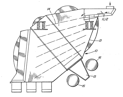
Figure 1 shows schematically a side view of a screening
machine with an integrated distributing and segregating device,
Figures 2a and 2b show an example of a distributing and
segregating device according to the invention,
Figures 3a and 3b show alternative designs for this
device,
Figures 4 through 4c show another example of a
distributing and segregating device, and
Figures 5 through 5c show an enlarged view of the
structure and organization of the distributing flaps in this
device.
Detailed Description
Figure 1 shows how the screening machine 10 consists
chiefly of the frame 13 with the screen cloths 14, the vibrator
base 15 and the vibrators 16. At the inlet of the screening
apparatus, i.e. above and before the top screen cloth 14 there is
a distributing and segregating device 11 and 12 attached as a


~
.

1~8~7~
-- 4
modular component so that a simple adaptation to di~ferent
requirements is possible by exchange of the device. The length
of the distributing and segregating device depends upon several
factors like material properties as well as width of the
screening apparatus. For very wide screening machines it is
possible to use e.g. two distributing devices side by side and in
practice have two inlets.
When the material leaves the distributi~g and
segregating device and arrives at the screen aloth it is
segregated and distributed completely so that the screening
process will be considerably facilitated i.e. the residence time
on the screen cloths will thereby be very much shorter and,
accordingly, the specific capacity increased. The distributing
and segregating device is in Figure 2a shown in cross-sectional
view and in Figure 2b from above. It consists of an inlet
opening 18 and an outlet opening 19 which leads to the screen
cloths, an enclosed box 17 between the side walls of which a
bottom part 20 is arranged. At the inlet base this bottom part
is shaped in a roof-like fashion 20a, while towards the outlet it
consists of a more shallow, flat part. By means of the roof-like
bottom part and its saddle-shape the fed material will be
distributed sideways. The vibration will then transport the
material towards the outlet and the screen cloths and at the same
time segregate it.
To improve the even distribution of the material a
vertically adjustable profile 21 can be arranged above the bottom
part 20b and the lower end of this profile can be shaped with
e.g. serrations 29 or castellations 30, as shown in Figures 3a
and 3b. It is also possible to attach adjustable deflecting or
guiding elements 22 to the bottom 20b to improve the distribution
furthar.
It is also suitable to fit an inspection port 24 to the
box 17 to facilitate adjustment of the distributing devices.
A different principle for the distribution is shown at
the distributing and segregating device 12 in Figures 4a-5c,


, . ` , .

~L2847~5
~.
-- 5 --
which also gives a horizontal transportation towards the screen
cloths. In this case the material is fed through the inlet 25 of
the box 23 and split into two flows by a roof-like element 26,
Afterwards, the material falls onto the flaps 27 which have
adjustable slopes (Figures Sa-5c).
After being split by the profile 26 the material move~
on the flaps 27 by two means; the vibration will move it to~7ard~
the screen cloths and the slopes will move it side~ays.
The slanted shape of the flaps 27 will permit the
material to flow over the outlet edge with an even thickness of
the flow. The vertically adjustable profile 28 enables further
shaping and directing of the flow of material; it Gould form a
kind of weir or be arranged ln a slanting fashion. When the
material has left this outlet edge it falls onto a feeder plate
where further segregation will take place, and from then onto the
screen cloths. The inlet opening 25 can of course be shaped
differently and also placed asymmetrically if the Gonditions so
require.


s

Dessin représentatif
Une figure unique qui représente un dessin illustrant l'invention.
États administratifs

Pour une meilleure compréhension de l'état de la demande ou brevet qui figure sur cette page, la rubrique Mise en garde , et les descriptions de Brevet , États administratifs , Taxes périodiques et Historique des paiements devraient être consultées.

États administratifs

Titre Date
Date de délivrance prévu 1991-06-11
(22) Dépôt 1986-06-06
(45) Délivré 1991-06-11
Réputé périmé 2001-06-11

Historique d'abandonnement

Il n'y a pas d'historique d'abandonnement

Historique des paiements

Type de taxes Anniversaire Échéance Montant payé Date payée
Le dépôt d'une demande de brevet 0,00 $ 1986-06-06
Enregistrement de documents 0,00 $ 1986-10-29
Taxe de maintien en état - brevet - ancienne loi 2 1993-06-11 50,00 $ 1993-05-27
Taxe de maintien en état - brevet - ancienne loi 3 1994-06-13 50,00 $ 1994-06-03
Taxe de maintien en état - brevet - ancienne loi 4 1995-06-12 100,00 $ 1995-06-07
Taxe de maintien en état - brevet - ancienne loi 5 1996-06-11 150,00 $ 1996-05-23
Taxe de maintien en état - brevet - ancienne loi 6 1997-06-11 150,00 $ 1997-05-22
Taxe de maintien en état - brevet - ancienne loi 7 1998-06-11 150,00 $ 1998-05-28
Taxe de maintien en état - brevet - ancienne loi 8 1999-06-11 150,00 $ 1998-06-10
Titulaires au dossier

Les titulaires actuels et antérieures au dossier sont affichés en ordre alphabétique.

Titulaires actuels au dossier
FREDRIK MOGENSEN AB
Titulaires antérieures au dossier
EGGERSTEDT, KARL HEINZ
Les propriétaires antérieurs qui ne figurent pas dans la liste des « Propriétaires au dossier » apparaîtront dans d'autres documents au dossier.
Documents

Pour visionner les fichiers sélectionnés, entrer le code reCAPTCHA :


Pour visualiser une image, cliquer sur un lien dans la colonne description du document. Pour télécharger l'image (les images), cliquer l'une ou plusieurs cases à cocher dans la première colonne et ensuite cliquer sur le bouton "Télécharger sélection en format PDF (archive Zip)" ou le bouton "Télécharger sélection (en un fichier PDF fusionné)".

Liste des documents de brevet publiés et non publiés sur la BDBC .

Si vous avez des difficultés à accéder au contenu, veuillez communiquer avec le Centre de services à la clientèle au 1-866-997-1936, ou envoyer un courriel au Centre de service à la clientèle de l'OPIC.


Description du
Document 
Date
(yyyy-mm-dd) 
Nombre de pages   Taille de l'image (Ko) 
Dessins 1993-10-20 4 128
Revendications 1993-10-20 3 138
Abrégé 1993-10-20 1 8
Page couverture 1993-10-20 1 16
Description 1993-10-20 5 232
Dessins représentatifs 2000-07-18 1 20
Taxes 1998-06-10 1 34
Taxes 1998-05-28 1 34
Taxes 1997-05-22 1 27
Taxes 1996-05-28 1 29
Taxes 1995-06-07 1 40
Taxes 1995-04-20 1 43
Taxes 1994-06-03 1 31
Taxes 1993-05-27 1 27