Sélection de la langue

Search

Sommaire du brevet 1286014 

Énoncé de désistement de responsabilité concernant l'information provenant de tiers

Une partie des informations de ce site Web a été fournie par des sources externes. Le gouvernement du Canada n'assume aucune responsabilité concernant la précision, l'actualité ou la fiabilité des informations fournies par les sources externes. Les utilisateurs qui désirent employer cette information devraient consulter directement la source des informations. Le contenu fourni par les sources externes n'est pas assujetti aux exigences sur les langues officielles, la protection des renseignements personnels et l'accessibilité.

Disponibilité de l'Abrégé et des Revendications

L'apparition de différences dans le texte et l'image des Revendications et de l'Abrégé dépend du moment auquel le document est publié. Les textes des Revendications et de l'Abrégé sont affichés :

  • lorsque la demande peut être examinée par le public;
  • lorsque le brevet est émis (délivrance).
(12) Brevet: (11) CA 1286014
(21) Numéro de la demande: 1286014
(54) Titre français: CONNECTEUR DE TELEPHONE A CONDENSATEUR DE DERIVATION
(54) Titre anglais: TELEPHONE CONNECTOR WITH BYPASS CAPACITOR
Statut: Durée expirée - après l'octroi
Données bibliographiques
(51) Classification internationale des brevets (CIB):
  • H01R 13/26 (2006.01)
  • H01R 13/33 (2006.01)
  • H01R 13/658 (2011.01)
  • H01R 13/66 (2006.01)
  • H01R 13/719 (2011.01)
(72) Inventeurs :
  • TALEND, DONALD RICHARD (Etats-Unis d'Amérique)
(73) Titulaires :
  • CORCOM, INC.
(71) Demandeurs :
  • CORCOM, INC. (Etats-Unis d'Amérique)
(74) Agent: SMART & BIGGAR LP
(74) Co-agent:
(45) Délivré: 1991-07-09
(22) Date de dépôt: 1987-08-11
Licence disponible: S.O.
Cédé au domaine public: S.O.
(25) Langue des documents déposés: Anglais

Traité de coopération en matière de brevets (PCT): Non

(30) Données de priorité de la demande:
Numéro de la demande Pays / territoire Date
901,824 (Etats-Unis d'Amérique) 1986-08-29

Abrégés

Abrégé anglais


ABSTRACT
A modular jack for telephones in which bypass
capacitors have been connected to the leads so as to
bypass noise and other high frequency signals. End
mounted ceramic capacitors extend from the leads to a
ground plane which is provided with flexible fingers
and which is connected to a suitable ground so as to
provide a grounding contact for the capacitors.

Revendications

Note : Les revendications sont présentées dans la langue officielle dans laquelle elles ont été soumises.


-6-
CLAIMS
1. A telephone jack comprising an insulating
body member formed with an opening for a mating
connector, a plurality of electrical contacts mounted
in said body member, a plurality of tombstone
capacitors with first ends in contact, respectively,
with said plurality of electrical contacts, an
electrically conducting planar member mounted to said
body member and formed with a plurality of flexible
fingers, respectively, engaged by the second end of
said plurality of tombstone capacitors, and means for
grounding said electrically conducting planar member.
2. A telephone jack according to claim 1
including an electrically conducting cover member
mounted to said body member over said electrically
conducting planar member and electrically connected to
said planar member.
3. A telephone jack according to claim 2
wherein said plurality of tombstone capacitors are
mounted so that their longitudinal axes extend parallel
to each other.
4. A telephone jack according to claim 3
wherein said electrically conducting planar member is
soldered to said electrically conducting cover member.
5. A telephone jack according to claim 3
including an electrically insulating member formed with
a plurality of holes in which said plurality of
tombstone capacitors are respectively mounted and said
insulating member mounted between said cover member and
said plurality of electrical contacts.
6. A telephone jack according to claim 5
including a printed circuit board formed with at least
one mounting opening, and said body member formed with
at least one mounting prong which is receivable through
said mounting opening to attach said telephone jack to

-7-
said printed circuit board and said plurality of
electrical contacts connected to circuit paths on said
printed circuit board.
7. A telephone jack according to claim 3
wherein said plurality of electrical contacts formed
with enlarged regions and said first ends of said
plurality of tombstone capacitors, respectively,
engaging said enlarged regions.
8. A telephone jack according to claim 6
including a conductive grounding area formed on said
printed circuit board and at least one electrically
conducting tab extending between said conductive
grounding area and said electrically conducting cover
member.
9. A telephone jack according to claim 6
including an electrically conductive planar plate in
electrical contact with said electrically conducting
cover member.

Description

Note : Les descriptions sont présentées dans la langue officielle dans laquelle elles ont été soumises.

--1--
TELEPHONE CONNECTOR WITH BYPASS CAPACITOR
.
DESCRIPTION
7 _ . _
This invention relates in general to
electrical contacts in jacks and in particular to a
novel modular telephone jack in which the contacts are
provided with bypass capacitors.
Standard modular telephone jacks are provided
with a number of electrical contacts such as six, eight
or more which make mating engagement with a male
ln contact which is received therein. Such prior art
jacks do not provide bypass capacitors to a ground
plane from the various contacts.
It is an object of the present invention to
provide end mounted ceramic capacitors which extend
between the contacts and a ground plane of the jack.
It is an object of the present invention to
provide a telephone female terminal in which the
various contactors of the terminal are provided with an
enlarged portion upon which are mounted monolithic
~0 surface mounted capacitors which extend to a ground
plane which is connected to a ground plane of a printed
circuit board or to another suitable grounding region.
Metal springs are provided which engage the
ends of the capacitors which provide for mechanical
~5 cushionin~ of the capacitors and for alignment.
other objects, features and advantages of the
invention will be readily apparent from the following
description of certain preferred emhodiments thereof
taken in conjunction with the accompanying drawings,
although variations and modifications may be effected
without departing from the spirit and scope of the
novel concept of the disclosure and in which:
ON`~E DR~WINGS
.
FIG. 1 is a front plan view of the novel
3s connector of this invention;
.:,- ~ ', .,
.

~2 ~
--2--
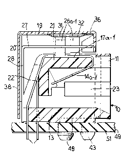
FIG. 2 is a sectional view taken on line II-II
from FIG. l;
FIG. 3 iS a top plane view of the invention
with portions removed;
FIG. 4 is a cut-away top view of the
invention;
FIG. 5 is a partial ~iew illustrating the
connector prongs and contacts;
FIG. 6 illustrates a modification of the
1~ invention
FIG. 7 is a sectional view taken on line VII-
VII from FIG. 6;
FIG. 8 is a top plan view with portions
removed; and
FIG. 9 iS a break-away top view of the
invention.
FIGS. 1-5 illustrate a first embodiment of the
invention which comprises a terminal 10 formed with a
plastic body member 11 in which a jack receiving hole
23 is formed in a front face thereof. The plastic
member as shown in the sectional view of FIG. 2 has a
bottom member 13 and a top member 21 and a back portion
~ plurality of electrical contact members 14a
through 14f have first portions which extend into the
openin~ 23 so as to make electrical contact with mating
terminals on a male plug received in the openinq 23 and
l~ave top portions 17a which pass over the top 21 of the
plastic member 11 and are formed with enlarged
capacitor contacts 18a through 18f in the top portions
30 17a through 17f of the contact which are offset .
relative to each other as illustrated in FIG. 3. The
rear portions of the contacts 14a through 14f pass down
beyond the rear portion 22 of the plastic member 11 and
extend through the bottom portion 13 of the plastic
member 11 and through a printed circuit board 49 which
'~, ' ' . ~ . ......... '- '' ,:
.
' '
,' , .. :' ,. :, ' ',

is provided with printed circuit contact area 51 to
make electrical contact with the ends 16a through 16f
of the contacts 14a through 14f as illustrated in FIGS.
1 and 2, for example.
~ounting prongs 47 and 48 pass through aligned
openings in the printed circuit board 49 for mounting
~lle female contact 10 on the board 49. A pluralit~ of
end mounted capacitors 26a through 26f extend through
an insulating sheet 27 which has a rear portion 28
1~ which is mounted relative to the plastic housing 11
such that first ends of the capacitors 26a through 26f
engage the electrical contact regions 18a through 18f
of the electrical contacts 14a through 14f.
A planar member 19 is formed with downwardly
1~ bent fingers such as 31 and 32 illustrated in FIGS. 2
and 4 which engage the second ends of the tombstone
~apacitors 26a through 26f and the member 19 is
electricall~ connected to a conductive core 36.
downwardly extending portion 20 of cover 36 is mounted
between downwardly extending portion 28 of the
insulating member 27 and the rear 38 of the electrical
conducting cover member 36. The member 19 may be
soldared to the cover member 36 by providing solder
through holes 37 formed in the finger member 19 as
illustrate3 in FIG. 4.
The cover member 36 is formed with sides 39
and 41 and grounding tabs 42 and 43 which extend from
the cover member 36 through openings formed in the
printed circuit board 4g and make electrical contact
with grounding regions on the printed circuit 51 so as
to ground the upper ends of the capacitors 26a through
26f through the fingers 31 and 32, the finger member 19
and the cover member 36~
In use, the terminal 10 is mounted on a
printed circuit board 49 with contacts 16a through 16f
: ' . - ~ '
,

which extend through board 49 electrically connected to
different terminals on the printed circuit paths 51.
The other ends of the capacitors 26a through 26f are
grounded through the grounding tabs 42 and 43 which are
connected to the side walls 39 and 41 of the
electrically conducting cover member 36. The male
member of the connector is inserted into the opening 23
to make electrical connection between the terminals 14a
through 14f and such contacts are grounded through
capacitors 26a through 26f. As illustrated in FIG. 5,
the cover member side walls 39 and 41 are provided with
tabs 46 which are deflected into mating opening formed
in the plastic member 11 to firmly attach the cover
member 36 to the plastic body member 11.
FIGS. 6-9 illustrate a second embodiment of
the invention wherein grounding is made to a front
grounding plate rather than to the printed circuit
board 49.
FIGS. 6-9 illustrate a modification of the
invention wherein the grounding arrangement has been
changed. This merely requires the modification of the
cover member and the plastic bod~ member. In this
embodiment, the cover member 136 has a front portion
152 which is connected to a conductive planar member
~5 151 by solder 153. The plastic member 111 has a front
rim 154 behind which the electrical conductive planar
member 151 fits as shown in FIGS. 7, 8 and 9. The
terminals 14a through 14f, the insulating plate 27, the
capacitors 26 have the same configuration as that of
the first embodiment. The cover member 136 is modified
so as to eliminate the extension tabs 42 and 43 which
are used for grounding in the embodiment illustrated in
FIGS. 1-5 and grounding occurs through the plate 151
which is connected by the solder 153 to cover member
35 136. This embodiment allows mounting and grounding to

~2~
conductive back panel.
Although the invention has been shown with six
electrical terminals, it is to be realized that it may
be modified to any desired number such as 8 or 10, for
example. Item 12 of FIG. 3 (flangeless) could be
modified as item 154 of FIG. 8 (flanged) with or
without 151 conductive mounting member.
Although the invention has been described with
respect to preferred embodiments, it is not to be so
1~ limited as changes and modifications can be made which
are within the full intended scope of the invention as
deEined by the appended claims.
. ~:, ';, : . ' ,
: . ,, . . :
. . :

Dessin représentatif
Une figure unique qui représente un dessin illustrant l'invention.
États administratifs

2024-08-01 : Dans le cadre de la transition vers les Brevets de nouvelle génération (BNG), la base de données sur les brevets canadiens (BDBC) contient désormais un Historique d'événement plus détaillé, qui reproduit le Journal des événements de notre nouvelle solution interne.

Veuillez noter que les événements débutant par « Inactive : » se réfèrent à des événements qui ne sont plus utilisés dans notre nouvelle solution interne.

Pour une meilleure compréhension de l'état de la demande ou brevet qui figure sur cette page, la rubrique Mise en garde , et les descriptions de Brevet , Historique d'événement , Taxes périodiques et Historique des paiements devraient être consultées.

Historique d'événement

Description Date
Inactive : CIB du SCB 2022-09-10
Inactive : CIB expirée 2011-01-01
Inactive : Périmé (brevet sous l'ancienne loi) date de péremption possible la plus tardive 2008-07-09
Inactive : CIB de MCD 2006-03-11
Lettre envoyée 2004-07-22
Inactive : TME en retard traitée 1999-04-29
Lettre envoyée 1998-07-09
Accordé par délivrance 1991-07-09

Historique d'abandonnement

Il n'y a pas d'historique d'abandonnement

Titulaires au dossier

Les titulaires actuels et antérieures au dossier sont affichés en ordre alphabétique.

Titulaires actuels au dossier
CORCOM, INC.
Titulaires antérieures au dossier
DONALD RICHARD TALEND
Les propriétaires antérieurs qui ne figurent pas dans la liste des « Propriétaires au dossier » apparaîtront dans d'autres documents au dossier.
Documents

Pour visionner les fichiers sélectionnés, entrer le code reCAPTCHA :


Pour visualiser une image, cliquer sur un lien dans la colonne description du document. Pour télécharger l'image (les images), cliquer l'une ou plusieurs cases à cocher dans la première colonne et ensuite cliquer sur le bouton "Télécharger sélection en format PDF (archive Zip)" ou le bouton "Télécharger sélection (en un fichier PDF fusionné)".

Liste des documents de brevet publiés et non publiés sur la BDBC .

Si vous avez des difficultés à accéder au contenu, veuillez communiquer avec le Centre de services à la clientèle au 1-866-997-1936, ou envoyer un courriel au Centre de service à la clientèle de l'OPIC.


Description du
Document 
Date
(aaaa-mm-jj) 
Nombre de pages   Taille de l'image (Ko) 
Page couverture 1993-10-21 1 13
Dessins 1993-10-21 2 85
Abrégé 1993-10-21 1 10
Revendications 1993-10-21 2 60
Description 1993-10-21 5 168
Dessin représentatif 2000-07-06 1 14
Avis concernant la taxe de maintien 1998-08-06 1 179
Quittance d'un paiement en retard 1999-05-17 1 172
Taxes 1999-04-29 2 66
Correspondance 2004-07-22 1 9
Taxes 1994-06-06 1 41
Taxes 1996-04-30 1 38
Taxes 1993-05-11 1 26
Taxes 1995-06-20 1 43