Sélection de la langue

Search

Sommaire du brevet 1286034 

Énoncé de désistement de responsabilité concernant l'information provenant de tiers

Une partie des informations de ce site Web a été fournie par des sources externes. Le gouvernement du Canada n'assume aucune responsabilité concernant la précision, l'actualité ou la fiabilité des informations fournies par les sources externes. Les utilisateurs qui désirent employer cette information devraient consulter directement la source des informations. Le contenu fourni par les sources externes n'est pas assujetti aux exigences sur les langues officielles, la protection des renseignements personnels et l'accessibilité.

Disponibilité de l'Abrégé et des Revendications

L'apparition de différences dans le texte et l'image des Revendications et de l'Abrégé dépend du moment auquel le document est publié. Les textes des Revendications et de l'Abrégé sont affichés :

  • lorsque la demande peut être examinée par le public;
  • lorsque le brevet est émis (délivrance).
(12) Brevet: (11) CA 1286034
(21) Numéro de la demande: 593079
(54) Titre français: MACHINE D'INSERTION DE COMPOSANTS ELECTRONIQUES
(54) Titre anglais: ELECTRONIC COMPONENT INSERTION MACHINE
Statut: Réputé périmé
Données bibliographiques
(52) Classification canadienne des brevets (CCB):
  • 356/22
(51) Classification internationale des brevets (CIB):
  • H05K 3/30 (2006.01)
  • H05K 13/04 (2006.01)
(72) Inventeurs :
  • JACKSON, RODNEY P. (Etats-Unis d'Amérique)
  • VANCELETTE, STANLEY R. (Etats-Unis d'Amérique)
(73) Titulaires :
  • JACKSON, RODNEY P. (Non disponible)
  • VANCELETTE, STANLEY R. (Non disponible)
  • EMHART INC. (Etats-Unis d'Amérique)
(71) Demandeurs :
(74) Agent: SWABEY OGILVY RENAULT
(74) Co-agent:
(45) Délivré: 1991-07-09
(22) Date de dépôt: 1989-03-08
Licence disponible: S.O.
(25) Langue des documents déposés: Anglais

Traité de coopération en matière de brevets (PCT): Non

(30) Données de priorité de la demande:
Numéro de la demande Pays / territoire Date
182,862 Etats-Unis d'Amérique 1988-05-02

Abrégés

Abrégé anglais


ABSTRACT
ELECTRONIC COMPONENT INSERTION MACHINE
An electronic component insertion machine
includes an insertion head having a pair of finger
assemblies which grip a component prior to
insertion. Each finger assembly has an actuating
lever secured to a pivot shaft and a finger holder
releasably clamped to the pivot shaft. The
actuating levers have surfaces which are maintained
in engagement throughout their displacement so that
rotation of one effects a conjoint rotation of the
other and are displaceable to advanced positions.
The finger holders are then unclamped, oriented to
their desired orientations relative to their
actuating levers and then clamped in position.

Revendications

Note : Les revendications sont présentées dans la langue officielle dans laquelle elles ont été soumises.


- 5 -

The embodiments of the invention in which an exclusive
property or privilege is claimed are defined as
follows:
1. A machine for inserting DIP electronic
components comprising:
mandrel means for supporting a DIP
component at a ready position;
insertion head means for gripping the DIP
component at the ready position and for inserting the
gripped component into a circuit board;
cut and clinch means for securing the
inserted component to the printed circuit board;
said insertion head means including first
and second finger assemblies each having;
a finger element,
a finger holder,
means for releasably securing said
finger element to said finger holder,
a pivot shaft,
means for pivotally supporting said
pivot shaft,
means for releasably clamping said
finger holder to said pivot shaft at a selected
orientation, and
an actuating lever secured to said
pivot shaft whereby rotation of said actuating lever
will rotate said finger element when said finger holder
is clamped to said pivot shaft, each of said actuating
levers having an axially extending curved surface
approximating an involute curve;
means for maintaining said curved surfaces
in engagement as said first actuating lever is
displaced from a first position to a second position so
that said second actuating lever will be conjointly
displaced from a first position to a second position;
and


- 6 -

stop means for stopping the displacement of said
second actuating lever at said second position thereby
stopping the displacement of said first actuating lever
at said second position,
whereby the orientation of said first finger
holder relative to the orientation of said first
actuating lever can be selected by rotating said first
finger holder around said first pivot shaft and
maintained by operating said first finger holder
clamping means, and
whereby the orientation of said second finger
holder relative to the orientation of said second
actuating lever can be selected by rotating said second
finger holder around said second pivot shaft and
maintained by operating said second finger holder
clamping means.

2. A machine for inserting DIP electronic
components according to claim 1, wherein said
maintaining means includes a spring.

3. A machine for inserting DIP electronic
components according to claim 1 wherein each of said
finger holders includes tongue means and each of said
finger elements includes groove means to facilitate the
changing of finger elements.

4. A machine for inserting DIP electronic
components according to claim 2, wherein said stop
means includes means for clamping the location of said
second position of said second actuating lever.


Description

Note : Les descriptions sont présentées dans la langue officielle dans laquelle elles ont été soumises.


ELEi::TRONIC COMPONEI~T INSERTION MACE~INE

~;PE:CI FI CATION

A dual in-line package ~DIP) component in~ertion
machine inserts DIP compo~ents into a circult board.
In state-of-the-art machines such as disclosed in U.~.
Patent Nos. 3,550,238 and 4,212,075, each component i 5
presented to a gripper mechanism which has a pair of
opposed jaws which grip the opposed rows of leads. The
gripper mechanism lowers the gripped componen~ to
partially insert the leads through receiving holes in
the circuit board whereupon the jaws are retracted to
release the component. A pusher located above the
component engages and fully seats the component. A
state of the art gripping mechanism is disclosed in
U.S. Patent No. 4,736,517 and the use of gear segments
to rotate locator arms in chip placement machines is
shown in U.S. Patent No. 4,527,324.
It is an object of the present invention to
provide an improved gripper mechanism for such a DIP
~ component insertion machine.
Other objects and advantages of the present
invention will become apparent from the following
portion of the specification and from the accompanying
drawings, which illustrate, in accordance with the
~5 mandate of the patent statutes, a presently preferred
embodiment of the invention.
Referring to the drawings:
Figure 1 is a front view of a gripper mechanism
for an electronic component insertion machine made in
3~ accordance with the teachings of the present invention:
Figure 2 is an oblique exploded view
illustrating one of the jaw assemblies of the ~ripper
mechanism shown in Figure 1; and


~g'

3~
-- 2 --
Figure 3 is a greatly enlarged view of a portion
of the finger actuating levers illustrated in Figure 1.
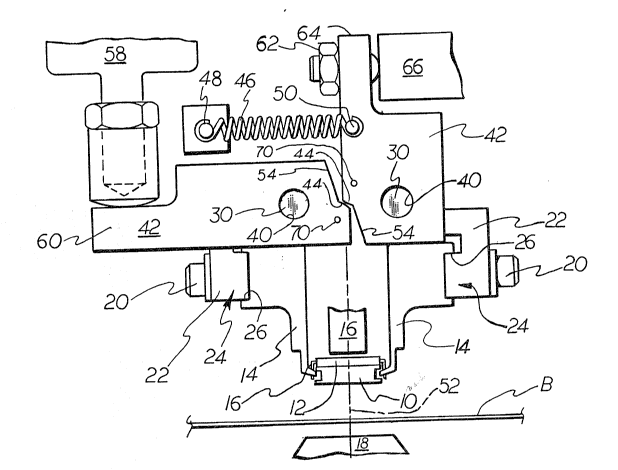
In a DIP component insertion machine, a mandrel
10 supports a DIP component 12 at a ready position
where opposed fingers 14, displaced to the advanced
position, illustrated in Figure 1, grip ~he leads 16 of
the DIP component. With the component gripped, the
mandrel 10 is horizontally retracted and the fingers 14
are lowered partially inserting the component leads
into a circuit board B. The opposed fingers are then
retracted away from the component, releasing the
component, and a pusher 16 is lowered to fully seat the
component. The leads are then cut and clinched by a
cut and clinch mechanism 18 to secure the component to
the circuit board.
Each of the opposed fingers 14 of the insertion
head illustrated in Figure 1 is secured by suitable
screws 20 to a finger carrier 22 and tongue 24 and
groove 26 portions facilitate the changing of the
fingers 14. A hole 28 (see Figure 2) extends through
each finger holder for receiving a pivot shaft 30. The
finger holder is split 32 above the hole and screws 34
(presented as going from the front to the back of the
finger holder instead of from back to front for
~5 purposes of illustration) will clamp the finger holder
to th~ pivot shaft 30.
The pivot shaft 30 for each finger is rotatably
supported within thru-holes 36 and 36A in a sha~t
support bracket 38 secured to the insertion head
housing. One end of each pivot shaft 30 is located
within a thru-bore 40 in its finger actuating lever 42
and that lever 4~ is secured (welded) to the shaft 30.
Rotative displacement of a finger actuating lever
accordingly results in conjoint rotational displacement
of the associated finger 14. The desired orientation

3l~ 3~
-- 3 --
of a finger 14 relative to its actuating lever 42 can
be set by loosening the clamp screws 34, rotating the
finger 14 relative to its lever 42 and then tightening
the finger holder screws 34 to clamp the finger holder
22 to the shaft 30. The pivot shaft has one diameter
33 passing through the lever and the shaft support
bracket 38 portion adjacent the lever and has a smaller
diameter 35 extending through the finger holder which
corresponds to the finger holder hole 28 and the
bracket portion 38 remote from the lever. The enlarged
diameter 33 increases the rigidity of the pivot shaft.
As can be seen from from Figure 3, the finger
actuating levers have axially extending, radiused,
engaging surfaces 44 which are maintained in continuous
engagement by a spring 46 extending between an
insertion head frame pin 48 and a pin 50 secured to the
vertical finger actuating lever 42. These radiused
surfaces 44 will maintain the fingers equally spaced
from the mid-plane of the component 52 throughout their
range of displacement. These radiused surfaces are
involute curves or curves which very closely
approximate true involute curves. Each lever has a cut
away portion 54 to permit relative pivoting of the
levers. To assure that the radiused surface will be
parallel to the finger secured to the pivot shaft, the
pivot sha~t 30 is first welded to its lever and then
the reduced shaft diameter portion 35 and the radiused
sur~ace 44 are machined. A tooling hole 70 is also
provided at the centerpoint of each radius.
Displacement of the fingers is controlled by a
pusher air cylinder 58 which engages the end portion 60
of the horizontal lever 42. Displacement of this
cylinder 58 simultaneously pivots the fingers from
their retracted positions to the illustrated advanced

~L%~ 3
-- 4 --
positions with the ~ingers continuously being precisely
maintained equidistant from the mid-plane 5~. A set
screw 62 secured to the end portion 64 of the vertical
lever 42 engages with a stop block 66 secured to the
insert head housing to define the advanced position of
the two operating levers 42. To set up the finger
assemblies, the finger holders 22 are unclamped by
loosening clamping screws 34. The pusher air cylinder
58 is operated to conjointly rotate the pivot levers
until further rotation of the vertical lever 42 is
stopped by stop block 66. With the actuating levers in
their fully rotated positions, each of the finger
holders is then rotated to locate the finger element at
the illustrated desired gripping location and then
clamped in position by tightening the screws 34.


~ . ~ '". , ' '

Dessin représentatif
Une figure unique qui représente un dessin illustrant l'invention.
États administratifs

Pour une meilleure compréhension de l'état de la demande ou brevet qui figure sur cette page, la rubrique Mise en garde , et les descriptions de Brevet , États administratifs , Taxes périodiques et Historique des paiements devraient être consultées.

États administratifs

Titre Date
Date de délivrance prévu 1991-07-09
(22) Dépôt 1989-03-08
(45) Délivré 1991-07-09
Réputé périmé 1995-01-10

Historique d'abandonnement

Il n'y a pas d'historique d'abandonnement

Historique des paiements

Type de taxes Anniversaire Échéance Montant payé Date payée
Le dépôt d'une demande de brevet 0,00 $ 1989-03-08
Enregistrement de documents 0,00 $ 1989-05-10
Enregistrement de documents 0,00 $ 1991-02-08
Taxe de maintien en état - brevet - ancienne loi 2 1993-07-09 100,00 $ 1993-06-15
Titulaires au dossier

Les titulaires actuels et antérieures au dossier sont affichés en ordre alphabétique.

Titulaires actuels au dossier
JACKSON, RODNEY P.
VANCELETTE, STANLEY R.
EMHART INC.
Titulaires antérieures au dossier
DYNAPERT, INC.
EMHART INDUSTRIES, INC.
Les propriétaires antérieurs qui ne figurent pas dans la liste des « Propriétaires au dossier » apparaîtront dans d'autres documents au dossier.
Documents

Pour visionner les fichiers sélectionnés, entrer le code reCAPTCHA :


Pour visualiser une image, cliquer sur un lien dans la colonne description du document. Pour télécharger l'image (les images), cliquer l'une ou plusieurs cases à cocher dans la première colonne et ensuite cliquer sur le bouton "Télécharger sélection en format PDF (archive Zip)" ou le bouton "Télécharger sélection (en un fichier PDF fusionné)".

Liste des documents de brevet publiés et non publiés sur la BDBC .

Si vous avez des difficultés à accéder au contenu, veuillez communiquer avec le Centre de services à la clientèle au 1-866-997-1936, ou envoyer un courriel au Centre de service à la clientèle de l'OPIC.


Description du
Document 
Date
(yyyy-mm-dd) 
Nombre de pages   Taille de l'image (Ko) 
Dessins représentatifs 2000-07-06 1 28
Dessins 1993-10-21 2 75
Revendications 1993-10-21 2 68
Abrégé 1993-10-21 1 21
Page couverture 1993-10-21 1 15
Description 1993-10-21 4 148
Taxes 1993-06-15 1 40