Note : Les descriptions sont présentées dans la langue officielle dans laquelle elles ont été soumises.
12~6~
REDUCING OIL CONTENT OF PRODUCED
WATER BY GAS FLOTATION
The present invention relates to a method of
and an apparatus for use in reducing the oil-content
of produced water by a floatation technique.
In this description and in the appended claims,
the expression "produced water" means a mixture of
oil and water having a gas in solution under relatively
high pressure. Produced water is, typically, a
component of well-head product obtained in a first
stage or production separator in the course of oil
production in the petroleum industry.
It is known that a dissolved gas flotation
technique has hitherto been used to treat produced
water drawn from a first stage or production separator
used for bulk separation of crude oil, gas and produced
water when fed directly with fluid from a well-head.
However, the dissolved gas flotation technique is
characterized by very small gas bubbles having
relatively low rise velocities which means that
separation by flotation of oil droplets is slow. Thus,
dissolved gas flotation units have to be large because
of the low rise velocities of the combined oil droplets
and gas bubbles. Also, substantial power consumption
is required for gas saturation in the liquid phase
and the process plant involved has the complication
of control equipment to control levels in a saturation
vessel. ~urther, safety equipment is required to
protect the saturation vessel from fire hazard and
over-pressure criteria.
It is also known that an induced gas flotation
technique can be applied for the separation of oil
from oily waters in the petroleum industry. This
technique is based on the generation of relatively
large gas bubbles which aid oil in water separation.
However, the large gas bubble diameters produced by
A
~28~613
this technique lead to lower oil clean-up efficiencies.
Also, significant power is required by a pumping system
for promoting gas entrainment for subsequent gas
breakout.
According to a flrst aspect of the invention,
there is provided a method for the gas flotation
treatment of a mixture including oil and water to reduce
the oil content of the water, the mixture being
continuously produced under a relatively high pressure
and having a gas naturally present in solution, said
method comprising the steps of: carrying the mixture
from a first vessel at said relatively high pressure
in first pipe means to a flotation vessel at a
relatively low pressure by way of first controllable
pressure letdown means arranged in the first pipe means;
selectively operating the first controllable pressure
letdown means to transfer mixture from said first vessel
to said flotation vessel according to a rate of
production of said mixture; providing second pipe means
having second controllable pressure letdown means,
said second pipe means extending from an influent
location upstream of the first controllable pressure
letdown means to a discharge location in communication
with the flotation vessel; and selectively operating
said second controllable pressure letdown means to
establish at said discharge location a flow of ~ixture
laden with bubbles of said naturally present gas
released from solution and caused by cavitation for
gas flotation treatment of mixture in the flotation
vessel.
According to a second aspect of the invention,
there is provided a method for the treatment of produced
water (as hereinbefore defined) to reduce the oil
content thereof, the mixure being continuously produced
under a relatively high pressure and having a gas
naturally present in solution, comprising the steps
-
~286~3
3.
of dividing the produced water into first and second
portions, modifying the first portion by reducing the
pressure thereof in a single stage, delivering the
modified first portion to a flotation vessel, modifying
the said second portion by reducing the pressure thereof
to effect a controlled formation of gas bubbles therein
of a desired mean size, said gas bubbles being released
from solution and caused by cavitation, and injecting
the modified second portion into the flotation vessel
to effect gas flotation treatment of the combined first
and second modified portions.
According to a third aspect of the invention,
there is provided apparatus for use in the treatment
of produced water (as hereinbefore defined) to reduce
the oil content thereof, the mixture being continuously
produced under a relatively high pressure and having
a gas naturally present in solution, comprising a first
vessel for holding the produced water under relatively
high pressure, a flotation vessel, first pipe means
extending between the first vessel and flotation vessel,
first controllable pressure letdown means arranged
in said first pipe means, second pipe means extending
from an influent location upstream of said first
controllable pressure letdown means and on a downstream
side of said first vessel to a discharge location in
communication with the flotation vessel, and second
controllable pressure letdown means for establishing
at said discharge location a flow mixture laden with
bubbles of said naturally present gas from solution
and caused by cavitation for gas flotation treatment
of mixture in the flotation vessel arranged in said
second pipe means.
It has been found that a more controlled and
varied gas (any gas with suitable solubility
characteristics) bubble diameter distribution can be
attained by means of the present invention without
. ~ .
=.~
12866~3
4.
the requirement for gas satu:ration vessels, excess
degassers, control equipment, pump recirculation
systems, and piping, which are pre-requisites of induced
and dissolved gas generation techniques.
In a preferred application of the invention
to the petroleum industry, the saturation of the
produced water which acts as the motive fluid containing
the gas available for flotation, is an inherent
characteristic of well-head fluid from certain oil
reservoirs prior to pressure letdown to atmospheric
conditions. Accordingly, for such wells the produced
water in a production separator operated at an elevated
pressure above atmospheric conditions is, by definition,
supersaturated compared to normal atmospheric pressure.
Therefore, by routing a portion of the produced water
from a production separator for injection to a flotation
vessel, a ready source of gas is available.
The portion constituting the injection flow
used as compared to the total flow rate of oily water
to be cleaned up depends on a number of parameters.
These relate to separator operating pressure, influent
concentration of oil in water, and control of the gas
evolution rate below that rate causing a slug flow
regime due to excess gas bubble coalescence.
The second controllable letdown means may be
selectively operable to generate bubbles within the
mixture flow in a multi-stage operation. E`or example,
in a first stage, primary letdown of pressure relatively
large bubbles by partial gas breakout from solution.
In a second stage these first bubbles are reduced in
size by being sheared through a shearing device such
as a diffuser plate i.e. a multiple orifice plate
assembly. In a third or final stage, full letdown
of pressure is performed and this releases a further
quantity of dissolved gas which will break out of
solution sufficient violence to produce cavitation,
1286~3
5.
thus further reducing by turbulence the size of the
bubbles from the second stage. However the pressure
letdown at the third or final stage may also be
controlled through nozzles so that a useful fraction
of the bubble size distribution is equal to or larger
than that nornally found in dissolved gas flotation
techniques so the second stage involving shearing,
may be omitted.
It is thus possible to produce a gas bubble
size distribution as required by varying the staged
letdown pressures to allow a wide range of oily water
flows and concentrations to be treated. Cleaned
effluent may therefore be produced for discharge, for
instance, to the sea from an off-shore oil, condensate
or gas production platform with the effluent meeting
statutory and other regulations concerning hydrocarbon
contamination levels.
It is also possible to provide apparatus
requiring reduced capital expenditure by the elimination
of any recirculation system as employed for induced
or dissolved gas flotation systems. This leads to
reduced maintenance and increased activity of operation
by increasing the mean time between failures. Greater
flexibility of operation is possible due to greater
permissible variations in flowrates. Also, a smaller
flotation vessel may be used since there is no need
for hydraulic loading imposed by recirculation flowrate,
In comparison with previously known techniques, there
are no energy related operating costs for generating
the gas bubbles.
Embodiments of the invention will now be
described, by way of example, with reference to the
accompanying drawings in which:
Figure 1 is a schematic diagram of an apparatus
constituting one embodiment of the
invention; and
...
lZ86613
6.
Figure 2 is a schematic diagram of a well-head
installation incorporating the apparatus
of Figure 1.
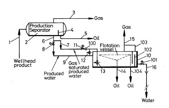
The apparatus in Figure 1 is for use in the
petroleum industry for bulk separation of crude oil
from water and gas at a well-head, and subsequent
clean-up of the produced water. The apparatus is
intended for use on an off-shore production platform,
but is generally suitable for use in on-shore
applications also.
The apparatus comprises a pipe 1 which supplies
well-head product in the form of a fluid or mixture
to a first vessel in the form of a production separator
2. The production separator operates at elevated
pressure and allows the product to be separated into
the three components. A gas component comprising
"natural gas" is given off and is removed via pipe
3, for storage or supply to a pipeline or for burning
off as a gas flare if the gas cannot be economically
used. The production separator 2 contains a baffle
4 forming a weir over which a substantial proportion
of the oil in the well-head product flows. The oil
is removed via pipe 5 for storage or to a pipeline.
The liquid part of the well-head product in the
production separator is sufficiently still to permit
a substantial proportion of the desired oil components
to float to the surface of the oil and water mixture
and the level within the separator 2 is controlled
so that oily water flow over the baffle 4 is minimized.
This oily water, hereinbefore defined as produced
water, is withdrawn from the separator 2 via a pipe
6 and is then split into two portions. An injection
flow portion flows along a pipe 7 at a rate which may
be between one and fifty percent of the flow rate in
the pipe 6. The other portion, comprising the remainder
of the produced water, is supplied to a first
A`
~:8~
controllable letdown means in the form of a level
control valve 8 and thence via pipe 9 to a flotation
vessel 20. The valve 8 is operable in a single step
of pressure letdown so as to contro] the level of the
oil and water interface in the production separator
2 according to production rate. The vessel 10 operates
at substantially well-head temperature and marginally
above atmospheric pressure and the pressure of the
said other portion is let down by the valve 8 in such
a way that stable control of separator interface level
results.
The injection flow portion of the produced water
in the pipe 7 is saturated, at the operating pressure
of the production separator 2, with gas and hence is
supersaturated with respect to atmospheric pressure.
This portion is supplied to a primary pressure letdown
valve 11 in which the letdown of pressure induces
relatively large bubbles as part of the gas breaks
out of solution. The produced water with the entrained
bubbles is then supplied via a shearing device 100,
for instance in the form of a diffuser plate comprising
a multiple orifice plate assembly, to final pressure
letdown valves 12 and 13, which may be combined or
provided independently. The valve 12 provides a full
flow bypass route Eor indirect injection of the
injection flow portion oE pipe 7 into the main fluid
stream in pipe 9 The bypass line incorporating the
valve 12 enhances maintenance access and can allow
the size of the vessel 10 to be reduced even further.
The primary letdown of pressure, for instance
from 5 Barg to 2:5 Barg over the valve 11 causes the
gas to break out of solution and be produced as
relatively large bubbles. The shearing device 100
then reduces the size of these large bubbles caused,
for instance, by 0:5 Barg pressure reduction producing
smaller bubbles which, nevertheless, are still
~;~86613
8.
relatively large compared with the bubbles produced
in a conventional dissolved gas flotation technique.
Following primary letdown of pressure, the
injection flow portion of produced water is still
saturated with gas in solution, but at a lower pressure.
The valve 12 and/or 13 provides final letdown of
pressure to liquid hydrostatic pressure within the
vessel 10 and the injection flow portion of produced
water is supplied (in the case of the valve 13 through
nozzles) into a lower part of the vessel 10 well below
the level of fluid in the vessel for the purpose of
mixing the oil droplets and gas bubbles. Thus, a gas
flotation effect occurs, but at a lower pressure than
is usual in dissolved gas flotation systems. More
of the gas breaks out of solution and cavitation occurs
so bubbles are formed larger than those produced in
the known dissolved gas flotation technique since the
pressure production over the valve 12 and/or 13 is
relatively small. By appropriate control of the
flowrate and pressure letdown between the valves 11
and 13, or 11 and 12, it is possible to adjust the
size distribution of bubbles from both the primary
and the final letdowns to achieve an optimum mean bubble
size. By causing cavitation in final pressure letdown,
bubble size can be reduced. These optimally-sized
bubbles rise to the surface of liquid in the flotation
vessel promoting separation of oil from water with
an optimized rise velocity of the combined oil droplets
and gas bubbles, that is, which is faster as compared
with smaller bubble sizes usually associated with
dissolved gas flotation, but slower as compared with
larger bubble sizes associated with induced gas
flotation.
The separated oil is removed from the vessel
by a combination of a full vessel length oil offtake
via a pipe 14, and by a notched weir via a pipe 104.
.ur
1~86~3
9.
A valve 101 is provided for controlling the level of
liquid ln the vessel 10. Low pressure gas from above
the liquid level is removed via a pipe 15 and is either
recovered, if economically viable, or is flared. Clean
water is removed from a lower part of the vessel via
a pipe 16 and is discharged, for instance to the sea.
A vent pipe 103 is connected above weir 102 to pipe
15 to avoid pressure build up.
Figure 2 illustrates the use of the apparatus
of Figure 1 in an installation for an off-shore oil
production platform. Like reference numerals refer
to like parts and will not be described again.
The installation includes an oily water separator
vessel 17 which receives oily water from drains via
a pipe 18, condensate products via a pipe 29, and
service fluids via a pipe 20. Also, produced water
from the separator 2 can be supplied to the vessel
17 via a pipe 21.
The vessel 17 is provided with a pipe 22 which
conducts gas from the vessel to a low pressure vent,
either for recovery or for flaring. Oily water from
the lower part of the vessel 17 is supplied via a pipe
23 and the pipe 9 to the flotation vessel 20 for
cleaning. Oil from the upper levels of fluid in the
vessel 27 is removed, for instance by a weir, and
supplied via a pipe 24 to a recovered oil tank 25.
Oil, still partly contaminated with water, from
the flotation vessel 10 is supplied via the pipe 14
to a gravity separator tank 26. The tank 26 is provided
with a pipe 27 for removing gas to a low pressure vent.
The fluid in the gravity separator tank 26 is retained
for a time sufficient for further separation of oil
from water and the upper layer of oil is removed, for
instance by means of a weir, and supplied via a pipe
28 to the recovered oil tank 25. Oily water from the
lower part of the tank 26 is removed and fed back via
-r .
1 Z8~613
10 .
a pipe 29 and the pipe 9, into the flotation vessel
10 for further purification.
The recovered oil tank 25 is provided with a
submerged pump 30 for supplying oil from the tank under
pressure to a pipe 31. The recovered oil tank 25 is
provided with a pipe 32 which conducts gas to a low
pressure vent header for recovery or for flaring.
The pressurised oil is then supplied to the pipe 5.
If necessary, some of the recovered oil from the tank
30 may be fed back via a pipe 33 to the production
separator 2.
An oily water sea sump 34 is provided for
receiving fluid from the tank 25 typically in an upset
condition and from various other sources. This sea
sump is of conventional type and will not be described
further.
In use, the production separator 2 receives
well-head fluid and performs three or four phase
separation i.e. oil, gas, produced water, and
occasionally sand. The oil is present as a primary
dispersion in the well-head fluid and a substantial
degree of separation is achieved in the separator 2.
However, a secondary dispersion of oil remains in the
produced water in the form of droplets having a diameter
which is typically between 5 and 100 microns. Gravity
separation techniques are not effective for the produced
water because of the requirement for high residence
times, thus requiring large vessels, which would be
necessary in order for separation to take place. Such
large vessels are impracticable and uneconomic,
especially for off-shore production platform
environments.
The injection flow portion of produced water
whose pressure is let down in the valves 11 and 13
and which passes through the diffuser pate immediately
downstream of the valve 11 produces bubbles within
.. ..
~28~ 3
11 .
the flotation vessel 10 having a bubble size or diameter
range from 30 to 1000 microns. The range may be
controlled by control of the valves 11 and 13 and the
design of the diffuser plate so as to provide bubbles
within a particularly desired range of diameters.
The apparatus achieves bubble generation within the
range of 0 to 20 percent by volume of gas at standard
temperature and pressure (STP) of influent volume
without the need of a recirculatlon system around the
flotation vessel 10. This contrasts with the known
induced gas flotation technique, which produces bubbles
having a typical diameter range of 500 to 2000 microns
but requires a recirculation rate of 25 to 100 percent
relative to influent rate, and known dissolved gas
flotation techniques which normally produced bubbles
having a diameter range of 30 to 120 microns and require
5 to 10 percent recirculation.
The recovered oil from the flotation vessel
is removed, for instance by a combination of notched
weirs, fixed and variable level baffles or level control
valves, and has a higher concentration than the produced
water from the production separator 2. This recovered
oil is supplied under gravity or pumped to the gravity
separator tank 26 where the richer oil phase is readily
separated as the flotation vessel, by means of the
dispersed gas flotation, has already assisted in such
separation by tending to convert secondary dispersions
to that characterized as a primary dispersion. Thus,
the oil droplet dispersions are typically close to
or larger than diameters of 100 microns.
In one example of an apparatus and installation
of the types shown in the drawings, the production
separator 2 was operating with a throughput of over
620 cubic meters per hour, providing over 390 cubic
meters per hour of crude oil, over 230 cubic meters
- per hour of produced water, and approximately 7.5 tonnes
~86~13
12.
of gas for fuelling purposes. The influent oil in
water concentration relative to total hydrocarbon was
on average 100 milligrams per liter. The effluent
oily water concentration was approximately 25 milligrams
per liter together with a soluble content of
approximately 10 milligrams per liter, which amounted
to an overall removal efficiency for the apparatus
of approximately 83 percent. Eurther, the contamination
of the water flowing out of the flotation vessel was
below current statutory limits of 40 milligrams per
liter so that the water was suitable for discharge
directly into the sea.
Experience has shown that produced water
throughputs of greater than 130 cubic meters per hour
using an induced gas system do not maintain the
concentration of contamination in discharged water
below the statutory limit of 40 milligrams per liter.
Thus, it was not possible to increase the loading of
induced gas flotation units. Also, it has been found
that basic disso'ved gas flotation systems operating
at flow rates above 200 cubic metres per hour cannot
maintain contamination below 40 milligrams per liter
because of the inability of this system to deal with
transient variations of concentrations of oil in water,
as tends to occur in oil production.
The apparatus is thus capable of meeting present
requirements concerning concentration of contaminants
in water to be discharged, and can be adjusted to meet
even more severe conditions if necessary. The apparatus
represents a substantial simplification and saving
in cost with respect to previously known flotation
systems and permits greater throughputs than
conventional systems of similar size. Its use is
particularly suited to applications where stable foams
cannot be easily produced.