Note : Les descriptions sont présentées dans la langue officielle dans laquelle elles ont été soumises.
9~
1 53,927
DETECTION OF TRANSPOSITION GROUP SHORT CIRCUITS IN
MACHINE WINDINGS
BACKGROUND OF T~E INVENTION
The present invention relates to the testing of
windings for the purpose of detecting shoxt circuits
betwe~n adjacent transposition groups within the stator
coils of a large gas-cooled machine, particularly a
synchronous generator.
If a short circuit should develop between the
transposition groups of such a machine, it must, of course,
be located before a repair can be attempted. Heretofore,
this has been done by disconnecting the phase leads to
permit testing of insulation. Such a procedure, par-
ticularly since it involves unbrazing and then re-brazing
the phase leads, is costly and time consuming.
SUMMARY OF THE INVENTION
It is an object of the present invention to
simplify the detection and localization of short circuits
in such machines.
Another object o the invention is to permit such
testing to be performed without requiring any disconnection
of the phase leads.
The above and other objects are achieved,
according to the present invention, by a method for
nondestructively electronically detecting a short circuit
in a conductor system which is composed of two inductor
groups connected together to form a selected current path
when no short circuit exists, comprising:
- 128~1~l
2 53,927
disposing a least one current probe at a
selected location of the current path for sensing changes
in the current flowing in the path at the selected loca-
tion; and
injecting a fast rate-of-rise current pulse
into the path; and monitoring the response of the current
probe to provide an indication of the existence of a short
circuit.
The method according to the invention can be
applied to any gas cooled machine and was developed
particularly for the testinS~ of gas cooled four-pole
synchronous genexators.
BRIEF DESCRIPTION OF THE DRAWING
Figure 1 is a circuit diagram illustrating short
circuit testing of a pair of coil yroups according to the
invention.
Figure 2 is a diagram illustrating the waveforms
of test signals produced by the practice of the method
according to the invention.
DESCRIPTION OF THE PREFERRED EMBODIME~TS
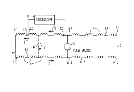
Figure 1 shows a pair of transposition groups
within a stator coil group constituting, for example, part
of a four-pole stator of a large, gas-cooled, a.c.
synchronous generator. Each stator coil ~roup may contain
many transposition groups and any two groups may be
treated as a paix. All transposition groups of a stator
coil group are brazed together at ends, or phase leads, 2.
In the illustrated embodiment, a transposition
group pair is shown over a length of eight half-coils 4.
Adjacent half-coils 4 are connected together via
coil leads at externally accessible terminals, or series
connection points, 6.n, where n=1....18. The generator
rotor winding is supplied with excitation current by an
exciter and the generator is disposed physically between
the exciter and a turbine. Each half-coil 4 extends
between the exciter end and the turbine end of the
generator.
~Z~19~L
3 53,927
In such coil systems, it is necessary to
determine the existence of, and locate, short circuits
between transposition groups, one exemplary short circuit
being shown by broken line 8. This is achieved, according
S to the invention, by applying current pulses having a fast
rate of rise between the two transposition groups, monitor-
ing the resulting current in the coils at selected points
along a path of current flow, and shifting the monitoring
location to localize any short circuit existing between the
pair of transposition groups.
Thus, as shown in Figure 1, a current pulse
source 10 is connected between terminals 6.5 and 6.14, each
of which is at the midpoint of its associated transposition
group. This midpoint is physically located at the ap-
propriate series connection in the coil group. Source 10can be connected between any other pair of terminals 6, but
each terminal 6 should be within a different transposition
group.
One or several current probes 12 are then
arranged to monitor the current flowing at selected
terminals 6. Each probe 12 is constituted by a sensing
coil bent in the form of an open loop, i.e. a loop which is
open at the free end of the coil, so that it can simply be
placed around a coil lead and can then produce an output
signal proportional to the rate-of-rise, or the time
derivative, of the current pulse waveform. Probes 12 are
connPcted to a dual input oscillo~cope 14 where the probe
output signals are displayed.
When steeply rising current pulses are applied
between two terminals 6, the waveform of the resulting
current flowing through each other terminal will depend on
whether a short circuit exists between that terminal and
source 10.
For example, if short circuit 8 is present, and a
current pulse is produced by source 10, a current i1 will
flow through terminals 6.4 and 6.13, while a current i2
will flow through short circuit 8 and a current i3 will
~2~g~9~L
4 53,927
flow through the coils located beyond short circuit 8,
where:
i1 = i2 + i3
and i2 will normally be much grleater than i3. As a result,
each pulse from source 10 will cause the probe 12 adjacent
terminal 6.5 to produce the output signal 20 of Figure 2
and will cause the probe 12 at terminal 6.2 to produce the
output signal 22 of Figure 2.
The substantial difference between the waveforms,
or peak, or average, values of these two signals can be
detected in various ways to provide an indication of the
existence of a short circuit. Such detection can be
achieved by visual observation of oscilloscope 14 or by
electronic comparison of the outputs of probes 12 subse-
quent to each pulse from source 10.
Each probe 12 may be of a type which can easilybe placed around a conductor and which can respond to
steeply rising current pulses. One suitable type is a
flexible current probe marketed by T~M Research, Inc., of
Alberquerque, NM. Such a probe can be connected to the
oscilloscope by a 50Q coaxial cable. Oscilloscope 14 could
be a Nicolet Model 2090.
For monitoring a transposition group pair, probes
12 can first be placed at terminals 6.5 and 6.1 or 6.10.
If the two probes produce comparable output signals, it can
be concluded that no short circuit between the transposi-
tion groups exists to the left of terminals 6.5 and 6.14.
Then probes 12 can be placed at terminals 6~5 and 6.9 or
6.18. Again, if comparable output signals are produced, no
short circuit exists to the right of terminals 6O5 and
6.14.
On the other hand, if the output signals from
probes 12 diEfer significantly from one another in a manner
which indicates that a short circuit exists, then either
probe c~n be moved from terminal to terminal to locate the
short. For l_xample, in the case of the probe locations and
short circuit 8 shown in Figure 1, probe 12 at terminal 6.5
12~ .9~
53,927
will produce an output signal 20 and probe 12 at terminal
6.2 will produce an output signal 22.
If the left-hand probe 12 is then moved to the
right from terminal to terminal, it will continue to
receive current i3, and to produce output signal 22 in
response to each pulse from source 10 until being placed at
terminal 6.4, where it will receive current i1 and produce
output signal 20. This will indicate that the short
circuit is located in the vicinity of terminal 6.3.
The method according to the invention can be
applied to any pair of winding transposition groups for
which the current path, in the absence of a short circuit,
is known. This current path is easily determined from the
stator coil design. ~he terminals of source 10 can be
connected to any two spaced, externally accessible series
connection points of a transposition group pair having at
least one coil between the connection points. However, it
is preferred that each connection point be constituted by
the series connection of a respective one of the groups
constituting the pair, and most preferably each connection
point should be at the midpoint of the series arrangement
of stator coils for constituting the respective transposi-
tion groupO
Preferably, each probe 12 is connected to a
respective input of oscilloscope 14 via a ilter. The
resulting current probe signals can then permit an accurate
distinction between a properly insulated transposition
group pair and a shorted pair.
By way of example, the current pulses pxoduced by
source 10 can have a rate-of-rise of 5 to 50 A/~s and a
duration of the order of 1-50 ~s, permitting a short in a
transposition group pair to be stressed with a voltage of
between about 20 volts and 200 volts. The pulses produced
by source 10 should have a triangular current waveform and
a rectangular voltage waveform. These pulses produce
readily discernable current probe responses.
~z~9~
6 53,927
The pulse polarity shown in Figure 2 has been
selected purely arbitrarily and could alternatively be
positive.
It will be understood that the above description
of the present invention is susceptible to various modifi-
cations, changes, and adaptations, and the same are
intended to be comprehended witnin the meaning and range of
equivalents of the appended claims.