Note : Les descriptions sont présentées dans la langue officielle dans laquelle elles ont été soumises.
~.~9014~
BACKGROUND OF THE INVENTION
1. Field of the Invention:
The present invention relates to a separable bottom-
end-stop assembly of thermoplastic synthetic resin for a
separable slide fastener.
2. Description of the Prior Art: :
The present invention and prior art are descrIbed with
reference to the accompanying drawings, wherein:
FIG. 1 is a fragmentary plan view of a separable
slide fastener having a separable bottom-end-stop assembly
~:embodying the present invention;
~ FIG. 2 is a transverse cross-sectional view taken
:~ along line II-II of FIG. l;
FIG. 3 is a fragmentary plan view of the separable
slide fastener, showing the manner in which the bottom-end-
::~stop assembly is separated;
FIG. 4 is a f`ragmentary perspective view of theseparable slide fasténer, showing the bottom-end-stop
assembly having been fully separated;
PIG. S is an enlarged transverse cross-sectional view:
taken along line V-V of FIG. 4, illustrating the manner in
which the stringer tape is clamped between a pair of mold
members; and
FIG. 6 is a fragmentary perspective view similar to
FIG. 4, showing a prior art bottom~end-strip assembly..
.
~29~)~42
U. S. Patent No. 4,221,026 issued September 9, 1985
discloses a separable bottom-end-stop assembly, for a slide
fastener, of a so-called lateral insertion type. As
reillustrated here in FIG. 6 of the accompanying drawings,
this type of separable bottom-end-stop assembly comprises a
pair of intercoupling male and female members A, B of
thermoplastic synthetic resin mounted on adjacent bottom
ends of opposed fastener stringers by molding. The male
member A extends along an inner longitudinal edge of one
stringer tape and has at its inner side a longitudinal
projection F and at its lower end a pivot pin C. The
female member B extends along an inner longitudinal edge of
the other stringer tape and has at its inner side a
longitudinal groove G receptive of the Longitudinal
projection F and at a position near its lower end E a
support hole D~opening obliquely :inwardly for receiving~the
~pivot pin C. For coupling the male and female members:A, B
to together, the pivot pin C:of the male member A is
inserted in the support hole D o~the female member B, and
then the male member A i5 pivotally moved about the pivot
pin C to cause the projectlon F to be laterally received~in
the groove G. : ~ :
In production, a pair of`opposed stringer tapes are
clamped between a pair of upper and lower mold halves
jointly deining a pair of: mold cavities each having a
contour corresponding to the shape of a respective one of
he male and female members A, B. Then molten
'
-2-
. ~ '', ' . . , ~' ' '
': ~ ",
' ,: ' , .
~Z9~)~42
thermoplastic synthetic resin is injected into the mold
cavities to form the male and female members A, B directly
on the respective stringer tapes. At that time, the
stringer tapes tend to become wavy in the mold cavities
because the latter are hollow and hence there are no parts
pressing the stringer tapes. As a result, the male and
female members axe molded on the wavy stringer tapes in
such a manner that the latter are locally and irregularly
exposed to the surfaces of the molded members, especially
to the surface of the male member, which has only a limited
thickness, thus impairing not only the appearance but the
bendng strength of the molded article.
If the male member has an increased thickness, the
gap between upper and lower guide flanges of a slider must
be increased; that is, the height of the guide flanges must
be short. With such short guide flanges, smooth and
correct coupling of opposed fastener eIement rows is
difficult to achieve.
SUMMARY OF THE INVENTION
It is therefore an object of the present invention to
provide a bottom-end-stop assembly, for a slide fastener;,
which is neat in appearance and has an adequate bending
strength, guaranteeing smooth coupling of opposed fastener
element rows.
According to the present invention, a bottom-end-stop
assembly for a sliùe fastener~comprises a pair of
intercoupling male anù female members of thermoplastic
synthetic resin adapted to bè molded on adjacent bottom
:
--3--
:
,
,
.
~l290142
ends of opposed fastener stringers. The male member has an
inner longitudinal projection and a pivot pin. The female
member has an inner longitudinal groove receptive of the
projection, and an inwardly opening support hole receptive
of the pivot pin for pivotal movement of the male member.
The male member has at least one aperture in the proj0ction
so that the stringer tape is clamped between a pair of mold
members so as not to become wavy during the molding. The
male member also has on opposite surfaces a pair of
reinforcig reidges remote from the inner longitudinal side
of the male member.
Many other objects, features and additional
.
advantages of the present invention will become manifest to
those versed in the art upon making reference to the
detailed description and the accompanying drawings in which
a preferred embodiment incorporating the principles of the
present invention is shown by way of illustrative example.
,~
DETAILED DESCRIPTION
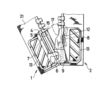
FIG. 1 shows a separable slide fastener comprislng a
p~air of fastener stringers 19, 20 each including a stringer
tape 21 carrying on and along its inner longitudinal margin
a row of coupling elements 16 in the form of separate
~,scoopes m~de of thermoplastic synthetic resin. A separable
bottom-end-stop assembly is mounted on adjacent bottom ends
of the stringers 19, 20 at the respective bottom end
portions of the~confronting inner tape-margins. The bottom
end portion is devoid of several coupling elements 16, the
number of which is not pertinent here. A slider 17 is
threaded on the opposed row of coupling elements 16 for
-a
: :
.
', :'. : :' '
. ~ ' : , ' '~` ' . ,. .:
:, , .. :.,,, ' ~ . ,':' . ,'' :
~2~0141t2
movement therealong to close and open the slide fastener.
Each stringer tape 21 has a core thread 15 extending along
its inner longitudinal edge. As shown in FIG. 1-4, the
separable bottom-end-stop assembly includes a pair of
intercoupling male and female~members 1, 2 of thermoplasti¢
synthetic resin mounted on adjacent bottom end portions of
the opposed inner longitudinal tape-margins by injection
moldlng. ~
The male member 1 has at its upper end a coupling-
element receiving portion 3 engageable with the lowermost
coupling element 16 on the companion stringer tape 21, at
its lower end a pivot pin 6/ and an inwardly (rightwardly
in FIGS. 1 and 2) facing longitudinal projection 5
extending between the coupling-element receiving portion 3
and the pivot pin 6.
The female member 2 has an inwardly tleftwardly ln
FIGS. 1 and 2) facing longitudinal groove 8 receptive of
the projection 5 of the male member 1, and in its lower
base portion g an obli~uely inwardly opening support hole
10 receptive of the pivot pin 6 oE the male member 1 so
that the latter is pivotable about the pivot pin 6 and
hense the support hole 10. Thus the projection 5 of the
male member 1 can be inserted into the groove 8 o~ the
female memher 2 substantially laterally thereof as
described below.
Each of the male and female members 1, 2 has a pair
of parallel reinforcing wings 13, 13 disposed one on each
-- 5 --
.: .
- ., . : -
,- ~
: :
:, .
: . , ~ ,
~90~4L2
side of the respective stringer tape 21, each reinforcing
wing 13 extending integrally from the respective member 1,
2 toward and terminating short of the outer longitudinal
tape edge and having a plurality of windows 14.
Most importantly, the male member 1 has at least one
aperture 4 in the projection 5 of the female member 2
substantially laterally thereof as described below.
Each of the male and female members 1, 2 has a pair
of parallel reinforciny wings 13, 13 disposed one on each
side of the respective stringer tape 21, each reinEorcing
wing 13 extending integrally from the respective member 1,
2 toward and terminating short of the outer longitudinal
tape edge and having a plurality of windows 14.
Most 1mportantly, the male member 1 has a
longitudinal aperture 4 in the projection 5 so as to expose~
a portion of the inner tape edge (including the core thread
5) to view, and also has a pair of longitudinal
reinforcing ridges 7, 7 disposed one on each surface of the
stringer tape 21 remotely from:the inner edge of the
projection 5. Although in the illustated embodiment the
male member 1 has only one elongated~ aperture 4, it may ;~
have~two or more short apertures. The female member 2~has
an aperture 12 so as to expose a portion o~ the inner tape
edge (including the core thread 15) to view.
Having the apertures 4, 12, the bottom-end-stop
assembly of the present invention is particularly
advantageous in that the inner longitudinal edge of the
.
,,,
: 6 -
, :, ': ~ '
.
'' :. ~ '
.. . . . . . . .
. .
, ' . ' . .: '
' : ' ' ' ' , ,. ' ~. : , . :
~L29~14;~
stringer tape 21 can be clamped stably between opposed
projecting portions 22a, 23a (FIG. 5~ of a pair of mold
members 22, 23 so as not to become wavy during the molding.
The aperture 12 of the Eemale member 2 is not absolutely
necessary because the female member 2 has an adequate
thickness along its entire length; But from an aesthetic
view point, it is preferrable to form the aperture 12 in
the female member 2 at a position generally symmetical with
respect to the aperture ~ in the male member l. The
longitudinal reinforcing rigges 7, 7 serve to compensate
for the loss in structural strength of the male member 1
due to the aperture 4.
In operation, when the slider 17 is moved downwardly
in FIG. l until the rear end of the slider 17 abuts against
an upper surface 14 of the base portion 9 of the female
member 2, the pair of rows of coupling elements 16, 16 IS
disengaged all the way, whereupon the male member l is
pivotally moved counterclockwise about the pivot pin 6
received in the support hole 10, as shown in FIG. 3. Then
the pivot pin 6 is removed from the support hole 10. Thus
the male member 1 has been completely separated from the
female member 2. On the contrary, to couple the male and
female member l, 2 together, with the slider 17 in fully
lowered position, the pi~ot pin 6 of the male member 1 is
inserted in the support hole 10 of the female member 2.
Then the projection 5 of the male member l is inserted into ..
the groove 8 of the female member 2, through the gap
_ 7 _ :
.' ' - - : ,, . , :
. . . .
.:
~29~ 2
between opposed guide flanges 18, 18 ~FIG. 2) of ~he slider
17, by pivotally moving the ~le member 1 clockwise in FIG.
3 about the pivot pin 6.
In the illustrated embodiment, the pin-and-hole
connection is employed. Alternatively, the male member 1
may have a hook, and the female member 2 may in turn have a
recess receptive of the hook.
According to the present invention, because of te
aperture ln the male member, it is possible to prevent the
inner longitudinal edge of the stringer tape from becomlng
wavy during the molding of the male member, without
increasing the thickness of the projection, thus making the
assembly neat in appearance free from local and irregular
exposition of the tape edge portion to the surface of the
male member. Further, the reinforcing ridges serve not
only to compensate the loss in structural strength of the
male member due to the aperture, but to improve the bending
strength in the longitudinal direction. Moreover, since
the reinforcing ridges extend alongside tbe path of the
slider, it is possible to a portion of a garment from be.ing
caught between the male member and the guide of the slider.
Although various m~inor modifications may be uggested
by tho8e versed in the art, it should be under8tood that I
wish to embody within the scope of the patent which may
issue hereon, all such embodiments as reasonably and properly
coma within the scope of my contribution to the art.
,
~ 8 -
. .
., ~ ,. ., '