Note : Les descriptions sont présentées dans la langue officielle dans laquelle elles ont été soumises.
This invention relates to portable align boring machines
and to attachment assemblies therefore.
Such machines are used to machine bores in equipment at
the place where the equipment is used, i.e. on-site. Portable
align boring machines are thus useful, for example, when the
equipment is too big and/or too heavy to be readily transported
to a machine tool workshop, or when there is no readily
available workshop in the area where the equipment is used.
Such machines can of course be conveniently used in a workshop
if desired.
~ portable align boring machine iB described in U.S.
Patent 4,406,566 (Bauer) issued September 27, 1983, the
contents of which are hereby incorporated by reference in this
application. The described machine comprises an annular drive
housing, a drive sleeve rotatably mounted in the housing, an
elongated boring bar positioned to extend through the drive
sleeve so as to rotate therewith and be capable of longitudinal
movement relative thereto, boring tool mounting means at one
end of the boring bar, means for rotating the drive sleeve and
consequently the boring bar, means for moving the boring bar
longitudinally relative to the drive sleeve while the boring
bar is rotating therewith, and an attachment assembly
attaahable to one end of the drive housing and attachable to a
workpiece or associated support to secure the drive housing to
the workpiece or associated support to enable the boring bar to
pass through the attachment assembly to the workpiece and to
enable a boring tool carried by the mounting means to engage a
bore in the workpiece.
Such a machine is extremely versatile and can be used
for many boring applications. For example, with different
appropriate boring tools fitted on the mounting means, the
machine can be used to service bores from about 1.375 inches
(3.5 cms) to about 24 inches (60 cms) in diameter and higher.
The boring bar may for example be up to about 8 feet (2.4 m) in
length or more.
The various attachment assemblies described in the above
mentioned U.S. Patent are suitable for many applications.
However, in order to enable such a portable align boring
machine to be more easily used for such applications and other
applications, an improved attachment assembly is desirable.
It is therefore an object of the invention to provide an
improved attachment assembly for portable align boring machines
of the kind referred to.
According to the invention, an attachment assembly
comprises:
a first attachment sub-assembly having a first tubular
member through which the boring bar can pass, the first
tubular member having means to enable the first tubular
member to be secured to the boring machine and having a
first inner bearing member with an inner bearing surface
to slidably and rotatably receive the boring bar, the
first tubular member also having an outer bearing member
with an outwardly curved and an outwardly facing bearing
surface, and a collar member surrounding the first
tubular member and having an inwardly facing curved
bearing surface slidably engaging the outwardly facing
curved bearing surface of the outer bearing member to
enable the collar member to move angularly relative to
the first tubular member, and
1 290~3~9
a second attachment sub-assembly having a second tubular
member through which the boring bar can pass, and a
secona inner bearing member with an inner bearing
surface to slidably and rotatably receive the boring
bar, the second inner bearing member also having an
outer curved bearing surface and the second tubular
member having an inner curved bearing surface engaging
the outer curved bearing surface of the second inner
bearing member to enable the second inner bearing member
to move angularly to the second tubular member, the
second tubular member having means to enable the second
tubular member to be secured to the workpiece or
associated support with the second inner bearing member
in alignment with the bore in the workpiece to be
machined,
the collar member of the first attachment sub-assembly
and the second tubular member of the second attachment
sub-assembly having co-operating means to enable the
first attachment sub-assembly to be secured to the
second attachment sub-assembly whereby the boring
machine with the first attachment sub-assembly secured
thereto can be secured to the second attachment sub-
assembly after the second attachment sub-assembly has
been secured to the workpiece or associated support and
aligned with the bore in the workpiece.
Advantageously, the inner bearing member of the first
attachment sub-assembly is positioned to engage the second
inner bearing member of the second attachment sub-assembly and
maintain the second inner bearing member in proper alignment
~ 2~3t)~3.r;9
when the collar of the first attachment sub-assembly is secured
to the second tubular member of the second attachment sub-
assembly.
The co-operating mean~ to enable the first attachment
sub-assembly to be secured to the second attachment sub-
assembly may comprise a series of bolts with manually
tightenable nuts thereon projecting from the second tubular
member of the second attachment sub-assembly and a
corresponding series of transverse open recesses in the column
member to enable to the collar member to be secured to the
second tubular member by transverse angular movement of the
collar member to cause the bolts to be received in the recesses
and by subsequent manual tightening of said nuts to the collar
member against the second tubular member.
The means to enable the second tubular member to be
secured to the workpiece or associated support in alignment
with the bore in the workpiece may comprise a first adjustment
plate having an aperture through which the second tubular
member passes and having means to position the first adjustment
plate in a predetermined position relative to the bore in the
workpiece, and a second adjustment plate having an aperture
through which the second tubular member passes, the first and
second adjustment plates having manually adjustable co-
operating means to enable the second adjustment plate to be
moved in one direction transverse to the length of the boring
bar, and the second tubular member and the second adjustment
plate having manually adjustable co-operating means to enable
the second tubular member to be moved in a direction
~1 ~90~
perpendicular to said one direction and transverse to the
length of the boring bar.
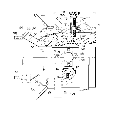
One embodiment of the present invention will be be
described, by way of example, with reference to accompanying
drawings, of which:-
Figure 1 is a side view of a portable align boringmachine with an attachment assembly in accordance with the
invention securing the machine to a support secured to a
workpiece,
Figure 2 is a plan view, partly in section, of the
arrangement of Fig. 1,
Figure 3 is a longitudinal sectional view of the boring
machine and the attachment assembly, with some parts of the
machine being omitted for clarity.
Figure 4 is a sectional view along the line 4-4 of
Fig.1,
Figure 5 is a sectional view along the line 5-5 of
Fig.3,
Figure 6 is a plan view partly in section, of the
attachment assembly,
Figure 7 is a exploded perspective view of a portion of
the second attachment sub-assembly showing the means for
aligning the second tubular member with a bore in the
workpiece, and
Figure 8 is a perspective view showing the first
attachment sub-assembly adjacent but not secured to the second
attachment sub-assembly.
Referring to the drawings, a portable align boring
machine 10 includes an annular drive housing 12 with a drive
~ X9~9.~C~
sleeve 14 mounted for rotation therein by means of bearings 16.
The drive sleeve 14 projects rearwardly from the housing 12,
and the projecting portion carries a driven pulley 20. A
hydraulically-operated drive motor 22 is secured to the drive
housing 12, with its drive shaft 24 carrying a drive pulley 26.
The driven and drive pulleys 20, 26 are connected by drive belt
27. An elongated boring bar 28 extends through the drive
sleeve 14 and is slidable longitudinally relative thereto. The
boring bar 28 has a longitudinal extending slot 30 engaged by
key 32 secured to the driving sleeve 14 so that the boring bar
28 rotates therewith.
A portion of the boring bar 28 which extends rearwardly
from the drive housing 12 beyond the pulley 20 passes through a
sleeve 34 rotatably mounted in a collar 36, the boring bar 28
being secured to the sleeve 34 by a clamp (not shown) so that
the boring bar 28 will rotate and move longitudinally with the
sleeve 34. The collar 36 has a laterally extending
intermediate portion 40 which extends to an internally threaded
sleeve 42. An advancing screw rod 44 extends through the
threaded sleeve 42 to an advancing mechanism 46 carried by the
drive housing 12.
The advancing mechanism 46 comprises a housing 47 from
which the advancing screw rod 44 projects, the advancing screw
rod 44 carrying a ratchet wheel 48 operated by a ratchet tooth
49. The ratchet tooth 49 is carried by a cam follower 50 which
is actuated by the cam 18 which rotates with the drive sleeve
14. As the drive sleeve 14 rotates, the ratchet wheel 48 is
actuated to rotate the advancing screw rod 44 incrementally, in
one direction or the other as selected by the position of the
~ ~ 9~C3~
ratchet wheel 49, with the result that the threaded sleeve 42
is moved longitudinally in an incremental manner as the boring
bar 28 rotates. The boring bar 28 is thus also moved
longitudinally in an incremental manner by the sleeve 34. The
advancing mechanism 46 also includes a manually-operable wheel
assembly 52 by means of which the advancing mechanism 46 can be
actuated manually to position the boring bar 28 longitudinally.
The wheel 52 is mounted on a shaft 51 carrying a bevel gear 51a
which engages a bevel gear 51b mounted on the advancing screw
rod 44.
The structure and operation of the boring machine as so
far described and illustrated is generally similar to that
describsd and illustrated in the above mentioned U.S. Patent
4,40Ç,566.
An attachment assembly 54 in accordance with the
invention is secured to the front end of the drive housing 12.
The attachment assembly 54 comprises a first attachment sub-
assembly 56 having a first tubular member 57 securable at its
rear end to the front end of the housing 12 by bolts 58. The
front portion 60 of the first tubular member 57 is cylindrical,
and the rear portion 62 flares outwardly to a flange 64 through
which the bolts 58 pass. The cylindrical front portion 60 of
the first tubular member 57 carries an annular outer bearing
member 66 with an outwardly curved and outwardly facing bearing
surface 68. The bearing member 66 is held in position relative
to the cylindrical front portion 60 of the first tubular member
57 by pins 70. The cylindrical front portion 60 also carries
an annular inner cylindrical bearing member 72 with an inner
bearing surface 73 which slidably receives the boring bar 28.
~1 ~9U~3^~9
The inner cylindrical bearing member 72 is a friction fit in a
recess 74 which extends rearwardly from the front face 76 of
the first tubular member 57.
The first attachment sub-assembly 57 also has a collar
80 with laterally extending open-ended recesses 86 (see Fig.6)
which can be engaged with a second tubular member as will be
described in more detail later. The collar 80 has an inwardly
facing and inwardly curved bearing surface 90 engaging the
outwardly curved and outwardly facing bearing surface 68 of the
outer bearing member 66 of the first tubular member 57.
The attachment assembly also has a second attachment
sub-assembly 78 comprising a second tubular member 84 whose
rear end has a flange 85 from which bolts 82 and nuts 83
project for attachment to the collar 80 of the first attachment
sub-assembly 56 as will be described in more detail later.
The second tubular member 84 contains an inner annular
bearing retainer 92 secured by set screws 94, the bearing
retainer 92 having a curved inner bearing surface 96. The
bearing retainer 92 retains a second inner bearing member 98
which has a curved outer surface 100 engaging the curved inner
surface 96 of bearing retainer 92 and an inner cylindrical
bearing surface 102.
The second attachment sub-assembly 78 also comprises a
pair of apertured adjustment plates 104, 106 by means of which
the second tubular member 84 can be aligned relative to a bore
to be machined. Each adjustment plate 104, 106 has a central
aperture 105, 107 through which the medial portion of the
tubular member 84 passes. On its front face, adjustment plate
104 has a projecting rim 108 surrounding the aperture 105, the
~ ~9()9.~9
rim 108 being engagable in an aperture llO in a support plate
112 as will be described in more detail later.
The rear face of adjustment plate 104 and front face of
adjustment plate 106 have mutually-engaging key-ways 114, 116
so that adjustment plate 106 can slide in one direction
transverse to boring bar 28 relative to adjustment plate 104.
Such sliding movement is effected by a manually operable
adjustment screw 118 which passes through a carrier member 120
secured to the adjustment plate 106 into a threaded aperture
121 in the adjustment plate 104. The carrier member 120 is
secured to adjustment plate 106 by screws 122, and adjustment
screw 118 is longitudinally restrained in carrier member 120 by
a force-fit washer 119. The adjustment screw 118 is manually
adjustable to raise or lower the adjustment plate 106 relative
to the adjustment plate 104.
The rear face of adjustment plate 106 and the front face
of flange 85 of tubular member 84 have mutually-engaging key-
ways 123, 124 which are perpendicular to the previously-
mentioned key-ways 114, 116 so that flange 85 (and hence
tubular member 84) can slide in a perpendicular direction
transverse to the bore 28 relative to the previously mentioned
direction. Such sliding movement is effected by a manually-
operable adjustment screw 126 which passes through a carrier
member 128 secured to flange 85 into a threaded aperture 130 in
adjustment plate 106. The carrier member 128 is secured to
flange 85 by screws 132, and adjustment screw 1~6 is
longitudinally restrained in carrier member 128 by a force-fit
washer 127.
~ ~o~c~
Use of the attachment assembl~ will now be described
with respect to the aligning and centering of the boring
machine 10 preparatory to machining a bore 132 in a workpiece
134.
The support plate 112 is secured in place with its
aperture 110 in general alignment with the bore 132 by first
support bracket assembly 135 (Fig.2) which is secured to the
front of the workpiece 134 by main bolts 136 and adjustment
bolts 138. A second support bracket assembly 140 (similar to
the first bracket support assembly 135) is similarly secured to
the rear face of the workpiece 134 by main bolts 142 and
ad~ustment bolts 144. The second support bracket assembly 140
is provided to support an attachment sub-assembly 146 which is
similar in construction to the second attachment sub-assembly
78 and similar but primed reference numerals are used to
identify its various parts.
The second attachment sub-assembly 78 is loosely mounted
on the support plate 112, that is to say with the projecting
rim 108 of the first adjustment plate 104 engaged in the
aperture 110 in the support plate 112. An anchoring nut 114 on
a threaded front end of the second tubular member 84 is screwed
into place but left loose. The attachment sub-assembly 146 is
then loosaly mounted on the support plate 112' in a similar
manner. The boring bar 28, with a cutting tool 133 mounted
thereon, is then passed through bearing 98 in the second
attachment sub-assembly 78 and bearing 98~ in the attachment
sub-assembly 146. As can readily been seen from the drawings,
any misalignment of the support plate 112 from the
9t)9~9
perpendicular to the bore 132 is accommoaated by movement of
the bearing member 98 within the second attachment sub-assembly
78.
Using conventional measuring instruments, the boring bar
28 is then centered in the bore 132 by manual adjustment of the
adjustment knobs 118, 126 of the second attachment sub-assembly
78 and adjustment knobs 118', 126~ of attachment sub-assembly
146 to effect accurate alignment. In the orientation shown in
Figures 7 and 8, adjustment of the knob 118 effects vertical
adjustment and adjustment of the knob 126 effects horizontal
adjustment. Thus, alignment of the boring bar 28 is effected
without the weight of the boring machine 10 present, thereby
avoiding difficulties in this respect which are encountered in
prior art arrangements.
When the alignment has been effected, the boring machine
10 with the first attachment sub-assembly 56 already attached
thereto is then mounted on the boring bar 28 and slid down to
cause the inner bearing member 72 in the first attachment sub-
assembly 56 to engage the inner bearing member 98 in the aecond
attachment sub-assembly 78, thereby angularly locking the
bearing member 98 in place. The collar 80 of the first
attachment sub-assembly 78 iB then tilted about outer bearing
member 66 as necessary and rotated to cause bolts 82 projecting
from flange 85 of the second tubular member 84 to enter into
the open recesses 86 in collar 80. The nuts 83 are then
manually tightened to secure the first attachment sub-assembly
56 to the second attachment sub-assembly 78. The boring bar 10
is then in proper alignment and centered with respect to the
~L ~'3U~3.~9
12
bore 132 to be machined. The boring machine 10 is then
operated in known manner to machine the bore 132.
The advantages of the invention will be readily apparent
to a person skilled in the art from the foregoing description
of a preferred embodiment, the scope of the invention being
defined in the appended claims.