Note : Les descriptions sont présentées dans la langue officielle dans laquelle elles ont été soumises.
1~3'~3~3
1 --
"IMPROVEMENTS IN AND RELATING TO TU~E EXPANDERS"
This invention relates to improvements in and to
tools for expanding the ends of tubes/pipes, and in
particular it relates to tube expanders of the type in
which a plurality of jaw elements are carried in a jaw
mount to be expandable by a tapered mandrel actuated
by a cam connected with a pivoted handle carried on the
tool body which also has a fixed handle extending
therefrom, the arrangement being such that by
manipulation of the pivoted handle, the mandrel is moved
axially into and out of the jaw elements to expand the
jaw elements, which have a complementary inner face,
to in turn expand a tube end fitted over the jaw
elements.
Tube expanders of the aforementioned type are well
known and in this regard reference is made to Australian
Patent Specification numbers 501,090 and 515,1591
Certain problems exist with this type of apparatus
mainly due to the force required to expand the ends of
tubes, such as copper tubes, and the need to have the
expansion accurately controlled so that when for instance
one end of the tube is to be expanded and the end of
another tube fitted into it and brazed or the like, the
fit shall be such that correct sealing of one end to
the other will result and will be capable of withstanding
the necessary pressures which need to be carried by tubes
of this type.
A further problem with prior art devices is the
requirement for fine tolerances during the manufacture
of the tool, specifically the mandrel, the cam handle
and the body. Furthermore, owing to wear, not
infrequently the cam handle and/or the mandrel need
replacement.
One object of the present invention is to provide
an improved tube expander tool which is able to give
very accurate adjustment of the expansion of the jaws.
3~3~
-- 2
A further object is to provide a satisfactory type of
cam on the movable handle and anti-Eric-tion assembly between
the cam on the handle and the mandrel which will ensure tha-t
the force required to move the mandrel forward is minimised.
A still further objec-t of this invention is to provide a tube
expander, the manufacture of which is very much simplified
and eliminates the need to maintain close tolerances in the
production of the tool body.
Yet another object of this invention is to provide a
tube expander which will enable wear to be adjusted out, and
which has simple, inexpensive replacement parts rather than
having to replace main component parts of the tool through
wear.
~ccorclingly, the pre~ent invention is in a tool ~or
expanding pipe or tube ends of the type comprising a tool
body having a passageway provided therein, an axially movable
mandrel located in the passageway and having a tapered end,
jaw mounting means arranged to be coupled with respect to the
tool body and comprising a plurality of expandable jaw
elements which are mounted for radial displacement upon axial
movement of the mandrel, the tool body having a fixed handle
projecting therefrom and a pivotal lever arm carried thereon,
the pivotal lever arm being provicled with a cam at or near
its pivoted end, the arrangement being such that by
manipulation of the lever arm, the cam co-acts with the
mandrel to cause the mandrel to move axially into and out of
the jaw elements to thereby expand same and to in turn expand
a tube end fitted over the jaw elements, and is the
3~ improvement comprising a replaceable cam facing of wear-
resistant material attached to the surface of said cam, ancl
being engageable with the inner end of said mandrel with
which the cam co-acts to cause the mandrel to move axially
into and out of the jaw elements.
.~
~3~31D
-- 3
Because the adjustable too.l head can be axially moved
when the lock screw or similar device is released, the exact
amount of expansion can be controlled by simply axially
moving the head and then locking it when at the required
extension which o~ course then governs the amount of
expansion of the jaws, as -the taper on the end of the mandrel
engages the inner faces of the jaws. Furthermore, the use of
an adjustable head greatly simplifies the manufacture of the 10 tool in that the need for fine tolerances in the production
of the tool body, cam handle and mandrel, is removed.
Preferably, the tool head comprises an axial hollow tail
which engages neatly into the passageway in the body, the
tail being adapted to be locked against axial movement when a
selected position for the head has been reached by means of a
lock screw or -the like, any form o:E locking being suitable to
prevent axial movement when required. mhe tail is pre.~erably
externally screw-threaded and threadably engages an internal
screw thread
- lZ~3~3~
-- 4 --
in the passageway of the tool body.
The tail and the passageway in the tool body can
be splined or otherwise arranged to prevent rotation
of the head in relation to the body i:E this is required
or where the body is made of a softer metal the aperture
can be sleeved so that the sleeve engages the tail on
the head.
The tool head preferably has a circular recess in
the surface facing the end of the too:L body, and the
body has an annular depending lip to engage into the
recess so that there is a barrier to the ingress of
foreign matter to the interengaging surfaces between
the tail and the body.
Preferably, the head has a screw-threaded portion
engageable with the jaw mount in which the jaw elements
of the jaw assembly are housed and the jaw elements are
locked to the jaw mount to prevent axial movement in
relation thereto but are free to move radially to allow
the jaws to be expanded.
In order to more fully explain the present
invention, an embodiment is described hereunder in some
further detail with reference to and is illustrated in
the accompanying drawings in which:
~ FIG. 1 is a perspective view of a tube expander
: 25 showing an expanding jaw assembly attached thereto,
FIG. 2 is a exploded perspective view of the
tool holder shown in Fig. l; and
FIG. 3 is a part longitudinal sectional view
of the tube expander of this invention (the closed
position of the pivoted lever arm being shown in
dotted lines).
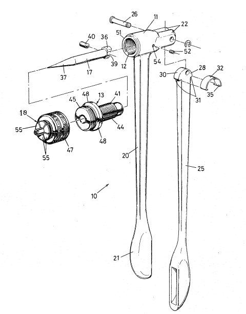
In this embodiment, a tube expander assembly 10
comprises a tool body 11 formed with an axial passageway
12 extending therethrough, an adjustable tool head 13
coaxially aligned with the tool body 11, the tool head
~3~3~
,. . .
13 having an axial bore 16 extending therethrough, a
mandrel 17 axially displaceable in the bore 16, and an
expandable jaw assembly 18 carried on the lower end of
the tool head 13 coaxially therewith. The expanding jaw
assembly 18 operates in accordance with known art and
does not form any part of the present invention.
The tool body 11 is provided with a fixed laterally
projecting handle 20 which is provided at its end with a
handle grip 21. The upper end of the tool body ll is
formed to have a pair of upwardly projecting spaced apart
lugs 22 between which a pivotal lever arm 25 is mounted
by means of a transverse pivot pin 26 which passes
through the lever arm 25 and the lugs 22. The lever arm
25 can be swung in the direction of arrow 27 shown in
Fig. 3 from an open position shown in full lines through
to a closed position shown in dotted lines in which the
lever arm 25 is approximately parallelly aligned with the
fixed handle 20.
The lever arm 25 is provided with a cam 28 at its
inner end, the cam 28 having an arcuate-shaped peripheral
cam surface 30, the cam 28 joining the lever arm 25
through a pair of opposed shoulders 31. A hardened spring
steel cam facing 32 clips on to the cam 28 and engages
the peripheral surface 30. The clip 32 comprises an
arcuate-shaped portion which terminates at its ends in
inturned flanges 35 whereby the clip 32 is able to be
readily removed and replaced through resilient engagement
with the cam 28.
The upper end of the mandrel 17 is provided with
an enlarged head 36, whilst the lower end of the mandrel
17 comprises a tapered portion 37 which extends through
the tool head 13 and into the jaw assembly 18. ~s the
pivot pin 25 is mounted eccentrically in relation to the
cam surface 30, upon actuation of the lever arm 25, the
tapered mandrel 17 is axially displaced and moves into
3~
-- 6
the jaw assembly 18. Unlike prior art devices where the
upper end face of the mandrel engages directly against a
co-operable cam face, in this embodiment, the enlarged
head 36 of the mandrel 17 is provided with a transverse
recess 39 in which is located an antifriction roller 40
which is arranged to engage the cam facing 32 to reduce
friction during the time that the cam facing 32 is in
engagement with the mandrel 17 to move it axially into
the jaw assembly 18.
The tool head 13, in this embodiment, comprises
a small diameter axially inwardly projecting tail 41
which has an externally screw threaded portion 44 which
threadably engages the internally threaded passageway 12
of the tool body 11, and a large diameter externally
screw threaded portion,45 which is arranged to be screw
threaded to the sleeve or collar 47 of the jaw assembly
18. The screw threaded portions 44, 45 are separated by
an annular flange 48, the diameter which is larger than
the outer diameter of the tool body 11. The axially inner
face 49 of the flange 49 is provided with a circular
recess 50 into which engages an annular depending lip 51
projecting from the end face of the tool body 11. With
the tool head 13 screwed to the tool body 11, the lip 51
engages within the recess 50 and forms a barrier to the
ingress of foreign matter to the interengaging surfaces .
between the tail 41 of the head 13 and the inner surfaces
of the tool body 11.
In order to lock the tool head 13 against axial
movement, when a selected position for the head has been
reached, there is provided a lock screw 52 which
threadably engages in a radial aperture 54 formed in
the wall of the body 11, the lock screw 52 when in its
locked condition, engages against an unthreaded portion
of the tail 41 adjacent its inner end.
Construction of the jaw assembly 1~ is in accord
3(;~
with known art and comprises a self-contained set of
radially expandable jaw elements 55 which are ~ounted
in the circular collar or sleeve 47 in such a way that
the segments can radially expand but are constrained
against any axial movement. The jaw elements 55 are
shaped so as to form a conical recess into which the
tapered end of the mandrel 17 engages in order to effect
the expansion of the jaw elements 55.
In this ~mbodiment, the pivotal lever arm 25 is
formed of cast aluminium which contrasts with prior art
- devices wherein the movable handle is normally of
hardened steel material. The replaceable hardened steel
cam facing clip 32 can be readily removed and replaced in
the event of any wear - instead of the entire lever arm
as is required in prior art units. Furthermore, the
antifriction roller, preferably of hardened steel,
significantly reduces friction between the clip 32 and
the mandrel 17 and thereby minimises wear between the
parts, but still further the antifriction roller permits
the device to be more readily actuated.
The jaw assembly of course can be variable in
dimension and for instance, the depth of the jaws can
be chanyed to allow the device to be used in tubes of
difference diameters and at the same time the actual
expansion of such tubes is variable by loosening the
lock screw or similar device and positioning the tool
head axially in relation to the tool body to select the
required limit to which the jaws can be expanded.
It will be realised from the foregoing that a
simple and effective form of tube expander is provided
and one which incorporates significant improvements in
comparison to known prior art de.ices.
.~