Note : Les descriptions sont présentées dans la langue officielle dans laquelle elles ont été soumises.
- 1 -
A SECURITY VESTIBULE ENTRY FO~ CONTR~LLED
A~CESS TO BANKS AND THE LIKE
DESCRIPTION
This invent;on relates to a security vestibuLe entry for
controlled access to banks and the like.
As is well known, for security reasons, vestibule entries
of banks and the like enclosures requ;ring controlled access,
are to disallow, in normal conditions, any persons from
entering and exiting an enclosure unchecked.
In the part;cular instance of banks, such security
vestibule entries must be made from bullet-proof materials to
resist robbing attacks.
Further, there exists a need for controlling a security
vestibule to its "shut" condition in order to cut off a person
therein, such as on the occasion of an alert situation resulting
from a conventional metal detector having been tripped.
For these reasons, security entries are usually equipped
with a barrier system vestibule formed basically of a booth-like
structure with two doorways; each doorway has a respective
door, for either manual or automatic openingr which is hinged
to the structure and provided with some interlocking closure
means, e.g. locks or magnets, which only permit one door to
be opened after the other door has been shut.
This first type of security vestibule is, however, of a
considerable size which cannot be reduced because this would
make the passage inconven;ent to use~ Moreover, ~he passage
times through the vestibule, which are tied to the door opening
and closing times, would still be unsatisfactory because, with
security vestibules of the type noted above, the passage times
- can only be shortened by increasing the door driving rates,
- which brings about obvious-safety as well as engineering
-
. .
~L29~
problems due to the heavy weight of such ballistic barrier
doors.
Other conventional security vestibules comprise booths
having bulLet-proof walls and automatically operated interlocked
doors slidable along runways; such prior vestibules, and in
particular those having sliding doors with an arcuate base for
sliding along circular runways, can be made smaller than the
first-mentioned type, but their construction is more complex
and their door opening/closing times continue to be unsatisfactory.
Also known are security vestibuLes ;ncluding a booth
apertured at opposed ends thereof, which are provided with a
circular base partition formed with a 90 opening. The partition
can be turned within the booth so as to bring its opening
to register with either of the booth apertures.
These known-type vestibules have the ~ell~î e-cognized
disadvantage that they hinder quick escaping from the enclosure
in an emergency, and fail to afford unobstructed way to
handcarts, as allowed instead by the previously reviewed
vestibules on disabling the door interlocking mechanisms.
An additional drawback of partitioned security vestibules
is that with angled entries where the booth apertures are
90 away from each other, in normal operating conditions, the
partition would have to complete a 27û rotation each time,
;n order to avoid communicating the two booth apertures
directly w;th each other, and this would evidently entail
a long passage time.
In order to reduce such passage time through the
vestibule, and specifically to shorten the time required to
open and close the doors, security vestibules have been proposed
.
: ~29~
which also include a booth with two apertures, but have a door
mounted at each aperture consist;ng of two sliding door w;ngs
adapted to be driven simultaneously toward and away from each
other.
In th;s way, the door opening, or closing, time is haLved,
but at the expense of a greatly complicated vestibule construction
and an increase of its bulk dimensions.
A further conventional security vestibule comprises a
bullet-proof booth having a cylindrical interior shape and
being provided with a revolving "gate" made up of plural
segments. A vestibule to this design allow simmultaneous in
and out passage, but have large sizes, hinder panic escape
from the enclosure, and are generally unreliable security-wise~
The problem underlying this invention is to provide a
security vestibule for controlled access, which has such
structural and operational features as to obviate the drawbacks
affecting the prior art.
rhis problem is solved according to the invention by a
security vestibule being characterized in tha~ it comprises
two walls having a base shape substantially following an arc
of a circle~ different diameters, and respective angular spans
whose combined breadth is no less than 360, said walls being
carried slidingly on respective concentrical circular runways
and forming doors for the vestibule.
The features and advantages of a security vestibule
according to the invention will be more clearly understood
from the following detaiLed description of a preferred
~ embodiment thereof, to be taken by way of example and not of
limitat;on in conjunction with the accompanying drawings.
.
.
2~38~
-- 4 --
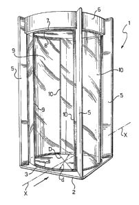
In the drawings:
Figure 1 is a perspective v;ew showing schematically a
security vestibule according to the invention; and
Figures 2 to 7 are schematical and fragmentary plan views
S of the security vestibule shown in F;gure 1 at various stages
of ;ts operation.
With reference to the drawing views, generally indicated
- at 1 is a security vestibule according to the invention, for
use as a controlled access entry to banks and the like enclosures.
The security vestibule 1 comprises a base plate 2 of
square shape, on which two concentricaL c;rcular runways are
formed, the outermost runway with a diameter D being designated
3, and the innermost runway with a slightly smaller diameter d
than the diameter D being designated 4.
Four vertical upr;ghts 5 having the same length are
mounted on the corners of the base plate 2.
The reference numeral 6 denotes an upper plate supported
on the uprights 5 and extending parallel to the base plate 2;
the upper plate 6 is also provided with two concentrical
circular runways 7 and 8, having respective diameters D and d
and arranged to face the runways 3 and 4.
The security vestibule 1 of this invention has two
sheet-l;ke walls 9 and 10 having respective circular arc-shaped
bases of predetermined angular breadth A and a, and diameter
D and d, respectively.
It is important to observe that the sum of the angular
breadths A and a, of the walls 9 and 10~ exceeds 360 by a
- small margin. Particularly in the example under consideration,
the angular breadths A and a are identical and equal to 190.
1~98~
, ~ .
-- 5 --
In addit;on, the walls 9 and 10 are bullet-proof and
formed preferably from ballistic barrier glass.
The wall pair, 9 and 10, extend between the plates 2 and
6, and are mounted for sliding movement along the runways 3, 7
and 4, 8, respectively.
According to the invention, the walls 9 and 10 constitute
access doors for the vestibule 1, as explained more clearly
hereinafter.
Also provided are motive means, known per se and no
further illustrated, for driving the walls 9 and 10 along their
respective runways, and conventional sensor means, such as
sensing platforms, photocells, and the like, for operating
said motive means, as well as control means, such as travel
limit switches, to stop said motive means and halt the walls
9 and 10 at selected positions.
The operation of the security vestibule 1 for controlled
access to banks and the like enclosures, will be described
herein below w1th reference to a starting condition under
which the vestlbule would be "closed", as shown in Figure 2.
Under that condition, the concave sides of the walls 9
and 10 face each other and the centerline of the vestibule 1,
which centerline is indicated at X-X and identifies a passage
direction through the vestibule ,-accordingly under that
condition, the passage through the vestibule 1, in the direction
shown by the arrow in the drawing, would be blocked by the
walls 9 and 10.
Also under that condition, the opposedly located walls
9 and 10 would def;ne an enclosed space therebetween~ -
It is important to observe that since the sum of the
.
angular breadths of the walls 9 and 10 is greater than 360,
such walls w1ll overlap each other by a predetermined distance
at the line X-X. In the example shown, the overlap is of 10.
On said sensor means becoming activated, such as on
account of someone approaching the vestibule from the enclosure
outside, the motive means will drive the waLls 9 and 10
simultaneously along their respective runways 3, 7 and 4, 8,
to cause them to complete an angular movement of about 45
(50 in the particular example under consideration). Thus,
an aperture about 90 in breadth is uncovered which faces
outside from the enclosure and through which access can be had
to the interior of the vestibule 1 (see Figure 3).
At this point, the motive means are again operated to
drive the walls 9 and 10, presently partly overlapping each
other, slidingly through approximately another 45, but in
the opposite d;rection, thereby the vestibule 1 is restored
to its "closed" condition ~see Figure 4) and the person inside
the security vestibule 1 can be checked and recognized.
Where the checking procedure is passed, e.g. if no metal
objects such as weapons and the like are detected, the motive
means will again drive both walls 9 and 10 through about 90
to uncover an aperture of about 90 toward the enclosure
, interior, through which the entering person can now be admitted
(see Figure 5).
After the visitor has gone through the security vestibule 1,
the motive means are once again operated to restore the
vestibule 1 to its original "closed" condition.
-The passage through the vestibuLe 1 in the opposite
direction, i.e. exiting the enclosure, takes place in exactly
.~2~
-- 7 --
the same way as described above.
It is important to observe that in the event of a rush
- out of the enclosure, the motive means for the vestibule 1 would
be operated, and one of the walls 9 or 10, preferably the wall
10~ would be driven along its respective runways 4 or 8 from
the "closed" position through an arc of 180 close against the
other wall, thereby the concave sides of either will be facing
in the same direction toward the line X-X. Thus, the passage
through the vestibule 1 is unimpeded (see Figure 6).
Where the small size of the security vestibule 1 disallows
an easy passage under the condition depicted in Figure 6, and
again on the occasion of a rush out of the enclosure, the walls
9 and 10 would be driven, the one through 45 and the other
135 so as to gather them together with their respective
concave sides facing in one d-irection, at about 45 to the
line X-X tsee Flgure 7).
The security vestibule of this invention has shown to be
highly reliable as well as uncommonly simple construction-wise
and compact in size, primarily on account of its two sliding
walls forming doors for the vestibule and providing a "closed"
condition of the vestibule for the benefit of the secure
enclosure.
In addition, owing to the substantially semicircular
base configuration of the two walls/doors, in order to open
and close the vestibule, small angular displacements of said
walls/doors are adequate. For this reason, and because such
displacements are performed simultaneously, the passage times
through the vestibule can be quite short.
An additi~onal advantage of the security vestibule according --
~2~
-- 8 ~
to the invention is that it can be readily assembled to fit a
wide range of access ways from a reduced number of components.
In particular, this vestibule may be used with either corner
entries or straight entries, as well as with so-called self-
operated security entries (cfot for example, Canadian patent
application No. 488,263, now patent No. 1,233,074 by the same
Applicant), wherein access is provided to the interior of a
building, or alternatively to a get-through space separated from
the building and only utilized on activation of a metal detector
mounted at the entry.
In this case, in fact, the sliding door movements may be
easily controlled by said detector to give access into the
building under normal conditions, or give access to the get-
through space by appropriate rotations of the walls.
: The security vestibule entry disclosed herein above is
obviously susceptible to many changes and modifications without
departing from the true scope of the invention as set forth in
the appended claims.