Note : Les descriptions sont présentées dans la langue officielle dans laquelle elles ont été soumises.
129893~
GUIDE FOR FASTENER DRIVING TOOL
The present invention relates to fastener driving
tools and more particularly to a guide assembly for locat-
ing a power fastener driving tool relative to a workpiece.
BackgrQund of the Invention
A typical pneumatic fastener driving tool in-
cludes a housing having a nose portion that is located rel-
ative to a workpiece at a position where a fastener, such
as a nail, is to be driven. When the tool is placed
against the workpiece, a movable safety member enables a
drive stroke in which a driver blade drives a fastener
along a drive track through the nose and into a workpiece.
Usually the tool is designed so that the fastener pene-
trates fully into the workpiece with the head of the fas-
tener countersunk to some degree.
Among the many uses to which fastener drivingtools have been put is the installation of siding in the
construction industry. Because of its advantages over con-
ventional wood siding and other alternative materials, pre-
formed hardboard siding is becoming more popular. Standardnailing techniques can lead to difficulty in the installa-
tion of hardboard siding. For example, countersunk fas-
tener heads can cause fracturing of the fibers of the hard-
board material at the exposed surface and a reduction in
the life of the material or its surface finish may result.
In addition, hardboard siding material is designed for op-
timum performance with fasteners installed a predetermined
distance from the edse of the siding, and carefully con-
trolled positioning is desirable.
A typical power fastener driving tool may cause
difficulties in the installation of material such as hard-
board siding because the tool cannot be controlled to pre-
cisely vary fastener penetration into the workpiece. In
addition, the tool cannot readily be located at a precisely
determined, optimum position relative to the siding mate-
rial. While a simple, fixed edge guide might be employed,
this approach would limit use of the tool to a single ori-
entation relative to the workpiece and would prevent use of
~Z9893~
--2--
the tool for other purposes or at other locations on the
workpiece.
Summary of the Invention
It is a principal object of the present invention
to provide a guide assembly for fastener driving tools ca-
pable of adjustably regulating the degree of fastener pene-
tration into a workpiece while accurately locating the fas-
tener without restricting tool orientation to a single
choice. Other important objects of the invention are to
provide a guide assembly suitable for use with widely used
existing fastener driving tools; to provide a guide assem-
bly capable of conveniently being mounted to the movable
safety of a fastener driving tool without interfering with
the operation of the safety or the tool; to provide a guide
assembly that is adjustable for different degrees of fas-
tener penetration; and to provide a guide assembly that can
be associated with a fastener driving tool to overcome
problems encountered in the installation of hardboard sid-
ing and similar materials.
In brief, the above and other objects of the in-
vention are realized by providing a guide assembly for use
with a fastener driving tool of the type including a hous-
ing having a nose defining a drive track and including a
driver element for driving the fasteners in a given direc-
tion along the drive track into a workpiece. The tool em-
ploys a safety member carried by the housing for movement
relative to the housing in the given direction between a
workpiece responsive position and an operating position.
Biasing means urges the safety toward the workpiece respon-
sive position.
The guide assembly of the present invention in-
cludes a guide member and adjustable mounting means sup-
porting the guide member adjacent the nose of the fastener
driving tool for adjustably mounting the guide member in a
selected one of a range of positions along the given direc-
tion for limiting the depth to which a fastener is driven
into the workpiece. An arm extends from the nose in a di-
rection transverse to the given direction, and an edge
1~98931
-3-
guide carried by the arm extends in the given direction be-
yond the safety member for locating the nose a predeter-
mined distance from an edge of the workpiece.
Description of the Views of the Drawing
The present invention together with the above and
other objects and advantages may best be understood from
the following detailed description of the preferred embodi-
ment of the invention illustrated in the accompanying draw-
ings wherein:
FIG. 1 is a side elevational view of portions of
a fastener driving tool equipped with a guide assembly em-
bodying the present invention;
FIG. 2 is a fragmentary, front elevational view
of the guide assembly taken from the line 2-2 of FIG. 1;
FIG. 3 is a sectional view taken along the line
3-3 of FIG. 2;
FIG. 4 is a sectional view taken along the line
4-4 of FIG. 2;
FIG. 5 is an exploded perspective view of compo-
nents of the guide assembly;
FIG. 6 is a view similar to FIG. 2 illustrating
the guide assembly in position for driving a fastener into
a workpiece;
FIG. 7 is a view similar to FIG. 6 illustrating
the completion of a fastener driving stroke; and
FIG. 8 is a view similar to FIG. 2 showing a dif-
ferent adjusted position of the guide assembly.
Detailed Description
Having reference now to the drawings, FIG. 1
shows a fastener driving tool generally designated as 10
equipped with a guide assembly generally designated as 12
and constructed in accordance with the principles of the
present invention. The features of the present invention
are applicable to many different types of fastener driving
tools used with many dif~erent types of workpieces. The
drawings illustrate the preferred embodiment in which tool
10 is a pneumatically powered tool for driving round head
1298931
--4--
nails 14 into a workpiece 16 comprising prefabricated hard-
board siding.
Tool 10 is shown in FIG. 1 in somewhat simplified
and schematic form since additional details of the tool are
not necessary to an understanding of the present invention.
A housing 18 includes a handle 20 and a head portion 22 in
which a piston 24 carrying a depending driver blade 26 is
mounted for reciprocal movement in a fastener drive direc-
tion. A magazine 28 carries a supply of fasteners 14.
A fastener drive track 30 (FIG. 3) is defined in
a nose 32 of the tool 10. A fastener feeding gate 34 is
operated in synchronism with piston 24 to position a single
fastener 14 in the drive track 30 prior to each drive
stroke. Fasteners 14 may be supplied in collated form
mounted along the length of a tape or carrier, and a tape
guide 36 guides the tape away from tool 10 after fasteners
have been driven therefrom.
Operation of the tool 10 in a fastener driving
stoke is controlled by a trigger 38 and a safety 40. The
safety includes a head portion 42, a bias spring mounting
tab 44, a guide leg 46 and an actuating foot 48. Safety 40
is mounted on the housing 18 of tool 10 for limited move-
ment in the fastener driving direction parallel to the
drive track 30. Head portion 42 slidingly engages the nose
32 (FIG. 3) and a guide pin 50 fixed with respect to the
housing 18 is slidably received in a slot 52 formed in the
guide leg 46 of safety 40. A safety biasing spring 54 bi-
ases the safety to the normal, workpiece responsive posi-
tion shown in FIG. 1 in which the nosepiece projects beyond
the end of the nose 32.
A fastener driving stroke is initiated when
safety 40 is moved to an alternate operating position and
the trigger 38 is depressed. When the tool is pushed
against the workpiece 16 with a force larger than the bias-
ing force of the spring 54, the spring 54 is compressed andthe actuating foot 48 moves toward a trigger base or hous-
ing 56. A rod 58 moves into the trigger base 56 and oper-
ates in conjunction with trigger 38 to control a pneumatic
~291~931
63076-1079
valve system to carry out a fastener drive stroke and a fastener
feeding operation.
The preceding description of the fastener driving tool
10 is ample for a complete understanding of the present invention.
For further details of operation of fastener driving tools of this
type, reference may be had to the descriptions set forth in the
following Canadian application and United States patents.
Canadian application No. 533,542 filed April 1, 1987,
describes a pneumatic valving operation for carrying out a
fastener driving stroke and a fastener feeding stroke in a
pneumatic fastener driving tool. United States Patents No.
3,543,987 and No. 4,319,705 describe pneumatically operated
arrangements for feeding fasteners one at a time from a magazine
to a fastener drive track in synchronism with operation of a
fastener driving tool. United States Patents No. 4,264,028 and
No. 4,405,071 disclose arrangements for the operation of a
fastener driving tool in response to actuation of a trigger and a
safety.
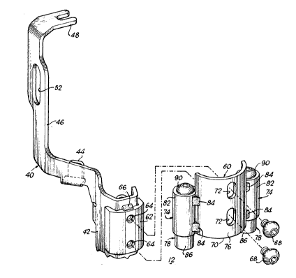
Guide assembly 12 can readily be mounted to the tool 10
or other fastener driving tool either during original manufacture
or by retrofitting. The assembly 12 includes a guide member in
the form of a shoe or yoke 60 carried by the head 42 of safety 40.
A mounting block 62 having a pair of tapped holes 64 is attached
to the front of head 42 by welds 66. A pair of fasteners 68 are
threaded into holes 64 to secure the member 60 in place.
In order to permit adjustment of the degree of fastener
penetration, the member 60 is mounted for adjustment relative to
1298931
63076-1079
the safety 40 and tool lO. When the tool is placed against
workpiece 16, a bottom edge or surfaGe 70 of member 60 engages the
workpiece. When the tool is moved relative to the workpiece to
displace the safety 40 and initiate a fastener driving operation,
the distance between the end of nose 32 and the workpiece 18 is
determined by the adjusted position of the member 60. The
adjustment is provided by a pair of slots 72 in member 60
receiving the
5a
1298931
--6--
fasteners 68. The fasteners may be loosened and retight-
ened with the member 60 in a selected position relative to
the safety 40 and tool 10.
A pair of arms 74 extend laterally in opposite
directions from a central portion 76 of member 60. Each
arm carries a retractable edge guide 78 permitting the tool
10 to be accurately positioned with drive track 30 located
a precisely determined distance from an edge 80 of work-
piece 16.
Each arm 74 includes a cylinder or sleeve 82 at-
tached by welds 84 to opposite edges of the central portion
76 of guide member 60. Sleeves 82 are each parallel to the
drive track 30.
Each edge guide 78 is a generally cylindrical el-
ement having a head portion 86 and a shank 88 capturedwithin the corresponding sleeve 82 by a fastener 90
(FIG.4). Each edge guide 78 is biased outwardly from
sleeve 82 by a guide biasing spring 92. When head portion
86 of an edge guide 78 is pushed against workpiece 16, the
spring 92 contracts and the edge guide 78 retracts to the
plane of the bottom edge 70 of the guide member 60.
Preferably the edge guides 78 are formed of a low friction
material such as plastic or the like and may rotate within
the sleeves 82 to limit friction as the guides are moved
along an edge 80 of workpiece 16.
Operation of the guide assembly 12 of the present
invention appears in FIGS. 6 and 7. In order precisely to
space a fastener from workpiece edge 80, the tool and guide
assembly 12 are located as shown in FIG. 6. A selected one
of the two edge guides 78 is in contact with the workpiece
edge 80 and as a result the drive track 30 is precisely lo-
cated a desired distance from the edge 80. Since two edge
guides 78 are employed in a symmetrical configuration, the
tool 10 may be held in the more convenient of two alterna-
tive orientations, one hundred eighty degrees apart. Thisfeature is important in making the tool 10 with the guide
assembly 12 convenient to use on a job site.
1298931
The guide biasing springs 92 have a smaller bias-
ing force or spring force than the safety biasing spring
54. Thus, as seen in FIG. 6, the tool may be placed in po-
sition for operation without compression of the safety bi-
S asing spring 54 or movement of the safety 40 relative tothe housing 18. Preferably, the springs 92 are selected so
that both springs 92 may be fully compressed before com-
pressi~n of the safety biasing spring 54 occurs. This per-
mits the tool to be used at any location on workpiece 16
without the guide assembly 12 interfering with operation of
the tool or the safety 40.
After the tool 10 and guide assembly 12 are posi-
tioned in preparation for a drive stroke as illustrated in
FIG. 6, the drive stroke may be initiated in the usual man-
ner by pushing the tool against the workpiece to move thesafety from the extended position on FIG. 6 to the operat-
ing position of FIG. 7, and by operation of trigger 38.
The conclusion of a fastener driving stroke is shown in
FIG. 7. The head 94 of fastener 14 is accurately driven
flush with the surface of workpiece 16. In the case of
hardboard siding, this flush penetration avoids problems
that can arise in a countersunk installation due to exposed
fractured fiber surrounding the fastener head. This accu-
rate penetration is achieved by adjustment of the guide
member 60 relative to the safety head 42 as described
above.
FIG. 8 in comparison with FIG. 2 illustrates a
different adjusted position of the guide assembly 12. In
FIG. 8 the guide assembly is adjusted to extend further
from the tool 10 and the nose 32. When the tool 10 is op-
erated with guide assembly 12 adjusted as shown in FIG. 8,
a fastener 14 will penetrate less deeply into workpiece 16.
Alternatively, the assembly 12 may be adjusted so that mem-
ber 60 projects less far from nose 32 than shown in FIG. 2.
This adjustment makes possible a countersunk installation
of a fastener 14 into workpiece 16.
While the invention has been described with ref-
erence to details of the embodiments shown in the drawings,
~Z98931
these details are not intended to limit the scope of the
invention as defined in the following claims.