Sélection de la langue

Search

Sommaire du brevet 1303518 

Énoncé de désistement de responsabilité concernant l'information provenant de tiers

Une partie des informations de ce site Web a été fournie par des sources externes. Le gouvernement du Canada n'assume aucune responsabilité concernant la précision, l'actualité ou la fiabilité des informations fournies par les sources externes. Les utilisateurs qui désirent employer cette information devraient consulter directement la source des informations. Le contenu fourni par les sources externes n'est pas assujetti aux exigences sur les langues officielles, la protection des renseignements personnels et l'accessibilité.

Disponibilité de l'Abrégé et des Revendications

L'apparition de différences dans le texte et l'image des Revendications et de l'Abrégé dépend du moment auquel le document est publié. Les textes des Revendications et de l'Abrégé sont affichés :

  • lorsque la demande peut être examinée par le public;
  • lorsque le brevet est émis (délivrance).
(12) Brevet: (11) CA 1303518
(21) Numéro de la demande: 566731
(54) Titre français: TUBE EN PLASTIQUE MOULE A NERVURES TRANSVERSALES EXTERNES ET PROCEDEET DISPOSITIF DE FABRICATION
(54) Titre anglais: PLASTIC TUBE WITH SOLID CROSS-RIBS ON THE OUTER SURFACE, A MOULDINGDEVICE THEREFOR; INSTALLATION COMPRISING SUCH A DEVICE AND A METHOD FOR MOULDING A PLASTIC TUBE
Statut: Réputé périmé
Données bibliographiques
(52) Classification canadienne des brevets (CCB):
  • 189/41
(51) Classification internationale des brevets (CIB):
  • B29C 47/00 (2006.01)
  • B29C 47/12 (2006.01)
  • F16L 25/00 (2006.01)
(72) Inventeurs :
  • HANSEN, FINN THOR (Danemark)
  • JARVENKYLA, JYRI (Finlande)
(73) Titulaires :
  • UPONOR N.V. (Antilles Néerlandaises)
(71) Demandeurs :
(74) Agent: GOWLING WLG (CANADA) LLP
(74) Co-agent:
(45) Délivré: 1992-06-16
(22) Date de dépôt: 1988-05-13
Licence disponible: S.O.
(25) Langue des documents déposés: Anglais

Traité de coopération en matière de brevets (PCT): Non

(30) Données de priorité de la demande:
Numéro de la demande Pays / territoire Date
8701164 Pays-Bas (Royaume des) 1987-05-14

Abrégés

Abrégé anglais


ABSTRACT


Plastic tube with solid cross-ribs on the outer surface, a
moulding device therefor; installation comprising such a device
and a method for moulding a plastic tube.

The invention relates to a tube having solid transverse
ribs at the outside and a smooth inner surface in which at
least one end has a smooth outer surface having a wall
thickness which may be chosen free, i.e. greater than, equal
to or smaller than the smallest thickness of the tube between
the ribs.
The invention also relates to a device for moulding a tube
according to the invention, an installation having such a
device and a method for producing a tube using such an
installation which includes a device according to the
invention.
In the device at least part of the half-moulds used for
forming comprises at least a smooth inner surface corresponding
to a section of tube having a smooth outer surface.

Revendications

Note : Les revendications sont présentées dans la langue officielle dans laquelle elles ont été soumises.


The embodiments of the invention in which an exclusive
right or privilege is claimed are defined as follows:

1. Tube made of plastic with a smooth inner surface
and an outer surface comprising solid cross-ribs,
characterized in that at least one end of said tube has a
smooth outer surface of predetermined length, wherein for a
certain tube the ratio of the volume of plastic per unit of
length of a tube section which has solid cross-ribs to the
volume per unit of a tube section which has a smooth outer
surface lies in the region of 0.5 - 1.4.

2. Tube according to claim 1, characterized in that
said ratio is essentially 1Ø

3. Tube according to claim 1, characterized in that
the incline in the transition section between the section
of a tube comprising ribs and a smooth end of the same pipe
lies between 0 and 90°.

4. Tube according to claims 1, 2 or 3, characterized
in that the end of the tube comprising a smooth outer
surface is evenly widened in order to be able to received an
end comprising ribs of another identical tube.

5. Tube according to claims 1, 2 or 3, characterized
in that the end of the tube comprising a smooth outer
surface is evenly widened in order to be able to receive an
end with a smooth outer surface in an unwidened state of
another identical tube.

6. Device for use in an installation for moulding a
tube comprising ribs according to any one of claims 1, 2 or
3, comprising at least two series of half-moulds, each half-
mould having a half-tube-shaped hollow form and the half-
moulds being movable along tracks, which tracks run
parallel to each other over a working path in a manner such
that, over said working path, the half-moulds complement


each other with forming of an annular mould around a
concentrically arranged smooth mandrel, in which at least
one pair of all pairs of half-moulds has a cavity with at
least a partially smooth inner surface whilst the half-
moulds of the remaining pairs have a ribbed inner surface,
characterized in that the ration of the volume per unit of
length inside a moulding cavity of a pair of half-moulds
locked around the smooth mandrel which correspond to a tube
section which has an outer surface comprising ribs to the
total volume per unit of length inside a moulding cavity of
a pair of half-moulds locked around the smooth mandrel
corresponding with a tube section of the same tube which has
a smooth outer surface lies in the region of 0.5 to 1.4.

7. Device according to claim 6, characterized in that
the volume ratio is essentially 1Ø

8. Device according to claim 6, characterized in that
at least one pair of all pairs of half-moulds has at least a
partially smooth inner surface which is not parallel to the
surface of said smooth mandrel; whilst said surface has at
least partially an incline of between 0 and 90° with respect
to the central axis of the device.

9. Installation for moulding a tube comprising ribs
formed by at least one extruder with an annular manifold and
a rib moulding device for use in such installation
comprising at least two series of half-moulds, each half-
mould having a half-tube-shaped moulding cavity, and the
half-moulds being movable along tracks which tracks run
parallel to each other over a working path in a manner such
that, over said working path, the half-moulds complement
each other during forming of an annular mould around a
concentrically arranged smooth mandrel, said extruder
providing a plastic tube, the internal diameter of which is
smaller than the external diameter of said mandrel,
characterized in that the rib moulding device for use in
said installation is a device according to any one of


claim 6,

10. Method for producing a tube made from plastic with
a smooth inner surface and an outer surface which has solid
cross-ribs in an installation according to claim 9,
characterized in that the extrusion speed and the speed of
movement of the half-moulds are adjusted in relation to the
desired ratio of the volume of plastic per unit length of a
section of a tube with an outer surface provided with solid
cross-ribs to the volume of plastic per unit of length of a
section of the same tube which is provided with a smooth
outer surface, if said ratio differs from 1, a constant
speed difference is maintained during a period of time which
is essentially equal to and coincides with the time period
which is necessary to permit forming of the continuous
length of the annular mould which has a moulding cavity with
a smooth profile.

11. Method according to claim 10, characterized in
that, accordingly, the desire ratio of the speed of the
half-moulds is adjusted to a value in the region of
approximately 0.5 to 1.4 times the extrusion speed.

-9-

Description

Note : Les descriptions sont présentées dans la langue officielle dans laquelle elles ont été soumises.


~3~3S~

Plastic tube with solid cross-ribs on the outer
surface, a moulding device therefor; installation
comprising such a device and a method for moulding
a plastic tube.
` . '
Firstly, the invent;on relates to a plastic tube
with a smooth inner surface and a solid outer surface com-
pr;sing cross-ribs.
Such a tube is known from German Patent Speci-
~;cation 2,709,395. In said patent specif;cation such atube ;s described together with a moulding of such a tube.
The tube described there;n has a smooth inner surface and
is provided with solid ribs on the outer surface over its
entire length.
Such a known tube which is provided with ribs
over its entire outer surface has the d;sadvantage that
connecting it to other similar sorts of pipes is relatively
difficult. The usual widening, in normal smooth tubes,
of one end in a manner such that the unwidened end of
another tube ~its therein has in practice hitherto not
yielded satisfactory results in the case of tubes with
solid ribs because the ribs are deformed during the widen-
ing operat;on which leads to uneven, non-round shapes
~h;ch may be actompanied by a lessening of the mechanical
strength.
The object of the present invention is to provide
a tube provided with ribs with a smooth inner surface
which is directly su;table for use in all known tube con-
nection methods.
According to the invention such a tube is charac-
terized in that at least one end of said tube has a smooth
outer surface of predetermined length, said end having a
wall thickness which is greater, equal to or smaller than
the smal(est wall thickness of the tube between the sol;d
ribs.
In particular, the wall thickness is greater
than the smallest wall thickness of the tube bet~een the


-

~3~3S~
solid ribs.
By making at least one end of a p;pe according
to the invention smooth and d;stributing at least part of
the volume of the solid ribs normally present there equally
over the wall th;ckness of the tube, a tube end is moulded,
on the one hand, which is suitable for all normal joining
methods while, on the other hand, said tube end may
satisfy, in a simple manner, the required tolerances of
roundness and strength.
In particular, ;n a tube according to the inven-
tion, the volume of plastic per length unit of the ribbed
section a~ounts to 0.5 to 1~4 times the volume per length
unit of the smooth section; in many cases, however, this
ratio may be 1Ø
The transition section between the ribbed sec-
tion of a tube and the smooth section of a tube is gener-
ally not sharp, but the transition section uil~ have an
incline; said incline is generally bet~een 0 and 90.
In the case of many types of tube connection it
i 20 is usual to widen one end of the tube in a manner such
that an unwidened end of another tube may be suitably
received therèin; as a ruLe, use ;s made of seal;ng means
which are appropriate for this purpose. The tube accor-
d;ng to the ;nvention may then, at its smooth end, be
widened in a manner such that an end comprising solid ribs
of another tube may be received; the widening may also
be produced in a manner such that an unwidened smooth
end of another tube may be received. In the latter case,
the tube accord;ng to the invention will have a smooth
outer surface at both ends; one of the two ends will then
be widened in a manner such that a smooth end of another
tùbe may be rece;ved.
The invention also relates to a rib-shaped
device for use in an installation for moulding a tube com-
prising ribs according to the invention as describedabove, which device comprises at least two series of half-
moulds; each half-mould having a half-tube-shaped moulding
cavity, and the half-moulds being moveable along tracks, which


~A


.. . ..

~3~
-- 3
tracks run parallel tu each other over a working Fath in
a manner such that, over said working path, the half-moulds
complement each other,dur;ng mould;ng,to an annular mould
around a concentrically arranged smooth mandrel. The
dev;ce accord;ng to the invention be;ng characterized in
that at least one pair of all pairs of hal~-moulds is
present, at least a sect;on of ~hich has a smooth inner
surface, whilst the half-moulds in the remaining pairs
have a ribbed inner sur~ace.
For such a dev;ce according to the invention ;t
is, furthermore, the case that, ;n part;cular, at least
one of all pairs of half-moulds is present, at least a
section of which has the smooth profile ~hich ;s not
parallel to the sur~ace of the above mentioned smooth
mandrel; said section has, at least partially, an ;ncline
of between Q3 and 90 with respect to the central axis of
the dev;ce.
The sum of the length of all half moulds with a
smooth inner surface uhich is parallel to that of the
smooth mandrel is essent;ally equal to the desired length
; of the surface of a tube ~;th a smooth outer surface.
In particular, in the device according to the
invention, the volume ratio per length un;t of the moulding
- cavity of the half moulds with a ribbed inner surface around
the mandrel to the moulding cavity of the half moulds with
a smooth inner surface around the mandrel has a value in
the region of O.S - 1~4; in many cases, said volume ratio
is essent;ally equal to 1Ø
The invention also relates to an installat;on
comprising an extruder and a r;b moulding dev;ce as des-
cr;bed above.
F;nally, the ;nvention relates to a method for
produc;ng a tube made`from plastic ~;th a smooth inner
surface and an outer surface comprising solid cross-ribs
using in an installation according to the invention as
has been descr;bed above ~hich is characterized in that
the extrusion speed and the speed of displacement of the
half-moulds of the invention are adjusted in relation to

:!~


~L3~35~8
-- 4
the desired ratio of the volume of p~astic per unit length
of a tube section ~ith ribs and a tube sect;on with a
smooth outer surface and, similarly, the desired ratio of
the displacement speed of the half-moulds is adjusted to
a value in the region of approximately 0.5 to 1.4 times
the extrusion speed.
If the ratio dif~ers from 1.0, a constan~ speed
d;fference is maintained over a period of time which is
essentially equaL to and co;ncides with the time that is
necessary to permit formation, around a smooth mandrel, of
the number of moulds having a smooth inner surface, which is
required for the corresponding smooth section of a tube.
The invention w;ll now be described ~ith reference
to the dra~ing, in which:
Figure 1 shows a tube according to the invention
in cross-section, with a smooth outer surface at one end;
Figure 2 shows two tubes according to the inven-
tion connected together;
Figure 3 shows a tube provided with soLid ribs,
a central sect;on having a smooth outer surface;
Figure 4 sho~s an installation for moulding a
tube provided with ribs;
F;gure 5 shows in plan view a section through a
number of half-moulds of a device according to the ;nven-
tion.
Figure 1 shows a tube 1 uith a smooth inner wall2 and so~;d ribs 3 on the outer side. One end of the tube
has a smooth outer side 4 wh;le the transition section
between the smooth section 4 and the section where the
ribs 3 are located ;s indicated by 6~
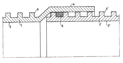
F;gure 2 shows two ribbed tubes connected together,
1 and 1', the smooth section 4 is w;dened in order to
receive the section of the tube 1' provided with ribs;
S shows that a packing material may be located between the
ribs.
Figure 3 shows a section of a continuously moulded
ribbed tube in which a sect;on of the length has a smooth
outer surface 4~ In order to obtain tubes with a smooth
.~
.


,

~3~3~

outer surface at both ends the section 4 in the centre
may be sawn through; if a smooth outer surface is required
a~ only one end, sawing through may take place at one of
the ends of sa;d smooth sect;on 4.
Figure ~ shows diagrammat;cally a device for
the continuous moulding of r;b tubes compris;ng a r;b
moulding dev;ce 10 and extruder 13.
The rib moulding device comprises two endless
bel~s 11 and 12 on which half-moulds 11' and 12' are
mounted. The half-moulds lock together around the smooth
end of an extrusion die ring 20 during ~ould;ng of an
annular hollow form.
The tube 22 delivered by the extrusion head 14
at the extrusion die ring 2û has an internal diameter
which ;s smaller than the external diameter of the smooth
mandrel 21. The half-moulds 11' and 12' deform the still
plastic material~ ~or example polyv;nyl chloride, of the
tube 22 and give the outer surface of the tube its profile.
The moulds provided with a ribbed inner surface
give a ribbed tube section 19. The moulds with a smooth
inner surface lead to a smooth tube section 18. In all
cases, the inner wall of the moulded tube ;s smooth.
The extruder 13 is driven by a drive means 15;
the rib moulding dev;ce is, as shown diagrammatically,
driven by drive means 16. The two drive means are coupled
via a control unit 17 which regul~ates extrusion speed
and transport speed of the half-moulds in accordance with
a desired ratio of the volume of plastic per Length unit
of a ribbed tube section and a smooth tube section.
The device sketched in Figure 4 shows a singLe
extrusion head to which all necessary plastic is supplied
in one del;very.
~f course, with the aid of co-extrusion, the
requ;red plastic may be supplied ;n several streams to a
special extrusion head connected to the rib mould;ng
device, in uhich case the tube is constructed in stages.
Finally, Figure 5 shows three cross-sections of
moulds ;n plan view; mould 30 is a normal mould with


~#~

~3~3S~8
- 6
r ibs 31.
Mould 32 is a mould ~ith a ribbed section 33 and
a smooth section 35; the transition section 34 has an
incline.
Mould 36 has a smooth inner surface 37.
The invention wilL no~ be further ;llustrated
with an example. A tube w;th an internal diameter of
180 mm with a wall thickness between the ribs of 2.0 mm
is moulded in an installation according to the invention.
The height of ehe ribs is 7.8 mm, the width of the ribs
is 2.55 mm and the pitch of the ribs is 16.9 mm. The
surface of the cross-section of the tube is, on averageO
1785 mm2.
The smooth end should have a wall thickness of
3.7 mm which corresponds ~ith a cross-section of 2134 mm2.
This may be achieved by changing the ratio of
the speeds of extrusion and transport of the half-moulds
from 1:1 to 1:0.85 when the half-moulds ~ith smooth inner
surface pass through the zone in which the mouthpiece of
; 20 the extruder supplies a ~ube.
As soon as the last mould with smooth inner
surface has been completed~ the speed ratio may be returned
to 1:1.
Throughout the description and following claims the
term section means to indicate a length of tube forming
a part of the total length of a tube.

Dessin représentatif
Une figure unique qui représente un dessin illustrant l'invention.
États administratifs

Pour une meilleure compréhension de l'état de la demande ou brevet qui figure sur cette page, la rubrique Mise en garde , et les descriptions de Brevet , États administratifs , Taxes périodiques et Historique des paiements devraient être consultées.

États administratifs

Titre Date
Date de délivrance prévu 1992-06-16
(22) Dépôt 1988-05-13
(45) Délivré 1992-06-16
Réputé périmé 2007-06-18

Historique d'abandonnement

Il n'y a pas d'historique d'abandonnement

Historique des paiements

Type de taxes Anniversaire Échéance Montant payé Date payée
Le dépôt d'une demande de brevet 0,00 $ 1988-05-13
Enregistrement de documents 0,00 $ 1988-11-25
Enregistrement de documents 0,00 $ 1992-10-21
Taxe de maintien en état - brevet - ancienne loi 2 1994-06-16 100,00 $ 1994-04-26
Enregistrement de documents 0,00 $ 1994-11-10
Taxe de maintien en état - brevet - ancienne loi 3 1995-06-16 100,00 $ 1995-06-09
Taxe de maintien en état - brevet - ancienne loi 4 1996-06-17 100,00 $ 1996-03-08
Taxe de maintien en état - brevet - ancienne loi 5 1997-06-16 150,00 $ 1997-04-21
Taxe de maintien en état - brevet - ancienne loi 6 1998-06-16 150,00 $ 1998-06-12
Taxe de maintien en état - brevet - ancienne loi 7 1999-06-16 150,00 $ 1999-06-11
Taxe de maintien en état - brevet - ancienne loi 8 2000-06-16 150,00 $ 2000-05-11
Taxe de maintien en état - brevet - ancienne loi 9 2001-06-18 150,00 $ 2001-05-16
Taxe de maintien en état - brevet - ancienne loi 10 2002-06-17 200,00 $ 2002-05-15
Taxe de maintien en état - brevet - ancienne loi 11 2003-06-16 200,00 $ 2003-05-14
Taxe de maintien en état - brevet - ancienne loi 12 2004-06-16 250,00 $ 2004-05-17
Taxe de maintien en état - brevet - ancienne loi 13 2005-06-16 250,00 $ 2005-05-16
Titulaires au dossier

Les titulaires actuels et antérieures au dossier sont affichés en ordre alphabétique.

Titulaires actuels au dossier
UPONOR N.V.
Titulaires antérieures au dossier
HANSEN, FINN THOR
JARVENKYLA, JYRI
WAVIN B.V.
Les propriétaires antérieurs qui ne figurent pas dans la liste des « Propriétaires au dossier » apparaîtront dans d'autres documents au dossier.
Documents

Pour visionner les fichiers sélectionnés, entrer le code reCAPTCHA :


Pour visualiser une image, cliquer sur un lien dans la colonne description du document. Pour télécharger l'image (les images), cliquer l'une ou plusieurs cases à cocher dans la première colonne et ensuite cliquer sur le bouton "Télécharger sélection en format PDF (archive Zip)" ou le bouton "Télécharger sélection (en un fichier PDF fusionné)".

Liste des documents de brevet publiés et non publiés sur la BDBC .

Si vous avez des difficultés à accéder au contenu, veuillez communiquer avec le Centre de services à la clientèle au 1-866-997-1936, ou envoyer un courriel au Centre de service à la clientèle de l'OPIC.


Description du
Document 
Date
(yyyy-mm-dd) 
Nombre de pages   Taille de l'image (Ko) 
Dessins 1993-11-01 5 86
Revendications 1993-11-01 3 128
Abrégé 1993-11-01 1 24
Page couverture 1993-11-01 1 18
Description 1993-11-01 6 220
Taxes 1999-06-11 1 29
Taxes 2000-05-11 1 28
Taxes 1998-06-12 1 29
Paiement de taxe périodique 1997-04-21 1 30
Paiement de taxe périodique 1996-03-08 1 39
Paiement de taxe périodique 1995-06-09 1 42
Paiement de taxe périodique 1994-04-26 1 46