Note : Les descriptions sont présentées dans la langue officielle dans laquelle elles ont été soumises.
~3613~
--1--
S P E C I F I C A T I O N
T I T ~ E:
MOLDED DISTAL STOP AND ATTACHMENT TO
FIX ORTHODONTIC APPLIANCE INTO MOWTH
BACKGROUND OF THE INVENTION
Field of the Invention:
The present invention relates to orthodontic devices
and more particularly to an attachment arrangement for arch-wires
or head-gear to the mouth.
Description of the Prior Art
Orthodontic appliances in the form of arch-wire or
head-gear are commonly used during orthodontic treatments to move
various teeth within the mouth to certain desired locations. In
order to move the teeth, the wires must be securely attached to
the teeth and this is generally accomplished by applying bands
to the teeth and then attaching the wires to the bands. In the
past, the wires are permanently attached to the ~ands, such as
by soldering which makes removal or adjustment of the wires very
difficult and time consuming.
The wires generally are provided with loops fo~med
therein to permit some measure of adjustment in the con~iguration
of the wire as the teeth move, however such adjustments also are
time consuming and must be done with a great deal of precision
in order to maintain a proper fit of the wire within the mouth.
SUMMARY OF THE INVENTION
The invention provides an attachment means for an
orthodontic appliance wherein the appliance incIudes an arch-
wire having a generally U-shaped configuration with two free
B
--2--
posterior ends each to be inserted through an opening in a mesial
end of a separate buccal tube comprising a covering formed on
each lateral side of the wire having a posterior end positioned
anterior to the posterior end of the wire to abut against the
mesial end of the tube and an anterior end including an
integrally formed resilient tab. The tab inc:Ludes an opening
therethrough sized to receive the posterior wire end.
In accordance with a further aspect of the invention
there is provided an attachment means for an orthodontic
appliance wherein the appliance includes an arch-wire having a
generally U-shaped configuration with two free posterior ends
each to be inserted through an opening in a mesial end of a
separate buccal tube to protrude from a distal end of the tube
comprising an elastic clamping arrangement fixed to the wire
having a first part which abuts against the mesial end of the
buccal tube, a second part which abuts against the distal end of
the buccal tube and an elastic part connecting the first and
second parts to provide a clamping action therebetween.
The present invention provides for an improved means
for attaching an orthodontic appliance such as an arch-wire or
head-gear wire to the teeth within the mouth, this attachment
means permitting relatively easy removal of the wire from the
teeth as well as easy position adjustability of the wire without
readjusting the configuration of the wire.
A molded stop covering which is molded onto the wire
and generally is in the form of a cylinder formed around the
wire. Since the wires are attached to the teeth by passing
through buccal tubes formed on tooth band~ or through buccal
~D3~
~2a-
tubes secured directly to the teeth, the stop covering is formed
with a diameter large enough to prevent its passage through the
tube. The stop covering can be trimmed to a desired length 50
that the most distal end of the covering rubs or abuts against
the mesial end of the buccal tube preventing the wire from ~oving
further back into the tube, and thereby fixes or stabilizes the
wire at that position.
A connector tab is integrally moldecl with the stop
covering and is an extension of thin diameter flexible material
which extends from the mesial section of the stop covering. The
connector tab has a small diameter hole in an end portion thereof
and the tab can be stretched between its connection point with
the stop covering and the hole. When the wire is positioned
correctly in the buccal tube and the distal end of the stop abuts
against the mesial end of the tube, a distal end of the wire
sticks out through the distal end of the tube. The tab can be
stretched and the opening at the end of the tab placed over the
protruding wire end such that when the stretching
~ 3~3~38~
-3
force on the tab is released, the tab will retain the
wire within the tube.
As treat~ent continues, the posterior teeth are
pushed in a distal direction and thus adjustment of
the positioning of the wire relative to the buccal
tube must be accommodated. This procedure is very
easily accomplished in accordance with the invention
by restretching the tab to release the tab from the
distal end of the wire, pulling the wire out of
engagement with the tube and placing an annular spacer
on the wire which will abut against the distal end of
the spacer and will then engage the mesial end of the
buccal tube so that the entire wire structure will be
moved forwardly to accommodate the rearward move~nent
of the teeth. The tab can then be restretched and
reattached to the distal end of the wire so that the
wire will again be securely held in place relative to
the teeth.
Due to the easy connection and repositioning of
the wire, the previously required steps of either
breaking the solder connections and resoldering or
readjusting the configuration of the wire are not
required thereby greatly reducing the time and effort
involved in these steps.
BRIEF DESCRIPTIOL~ OF T~E DRA~INSS
FIG. 1 is a perspective view of an arch wire
connected to a lower set of teeth.
FIG. 2 is an occlusal view of the attached wire
illustrated in FIG. 1.
FIS. 3 is a buccal side elevational view of a
molar band and the wire during a trimming step.
3~
--4--
FIG. 4 is a sectional view through the wire and
the molded covering and tab.
FIG. 5 illustrates the step of removing the
trimmed portion of the stop covering.
FIG. 6 is a view of the step of inserting the
wire into the buccal tube.
FIG. 7 illustrates the step of securin~ the wire
to the tube by use of the tab.
FIG. 8 illustrates the assembled position of the
wire and buccal tube.
FIG. 9 illustrates the use of an additional
spacer when repositioning the wire relative to the
tube.
DESCRIPTXON OF THE PREFERRED El~BODIMENTS
~IG. 1 illustrates a perspective view of a human
jaw 10 including an upper jaw 12 and a lower jaw 14.
During orthodontic treatment it is oftentimes
necessary to ~ove the posterior teeth rearwardl~ in
order to open up space for crowded anterior teeth and
to accomplish this it is known to use such orthodontic
appliances as arch-wires, bumpers, or head-gear.
An arch-wire 16 is illustrated in FIGS. 1 and 2
as being applied to the lower jaw 14. The arch-wire
could also be attached to the upper jaw or there could
be such a wire attachment to both the upper and lower
jaws. A head gear includes an arch-wire as
illustrated and further includes a band encircling the
posterior side of the head to provide additional
distal drive to the posterior teeth. One such device
is illustrated in my prior U.S. Patent No. 4,330,272.
Generally, the application of the arch-wire to the
teeth includes the placement of an encircling band 18
-5-
applied to a pair of posterior teeth such as the first
or second molars, one band being placed on each
lateral side of the mouth. The band 18 has
permanently attached thereto a buccal tube 20 which
S receives an end of the wire 16. Alternatively! the
buccal tube may be attached directly to the tooth by
an epoxy, or the tube may be attached to another
appliance such as illustrated in my identified patent.
The wire 16 illustrated in FIGS. 1 and 2
includes an anterior central loop 21 and a pair of
side loops 22 to permit the wire to be conormed to
the conEiguration of the patient's jaw. The wire also
generally includes a pair o~ laterally spaced bumpers
23 which are molded directly onto the wire and which
are engaged by the patient's lips to provid~ a
rearward or distal pressure on the wire which will
force the teeth to move distally as desired.
An attachment means 24 is provided in accordance
with the principles of the present invention which
permits the wire 16 to be easily secured to, rembved
from an repositioned relative to the buccal tubes 20
to which the wire 16 is to be connected. This
attachment means 24 is illustrated in greater detail
in EIGS. 3-9 where it is seen that the attachment
means comprises a molded covering 26 which is
generally cylindrical in shape and which covers a
length of the wire just anterior to a free posterior
or distal end 28 of the wire. The covering 26
preferably has a diameter approximately the same as
that of the buccal tube 20f but in any event should be
sufficiently large to prevent the covering 26 from
entering into the tube 20.
~ ~3~1~0
--6--
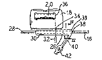
Once the wire 16 has been adjusted in
configuration to fit the patient, the wire can be put
in place along side the tube 20 and a distal or
posterior portion 30 of the covering 26 can be trimmed
away by a knife 32 (FI~. 3) so that a remaining distal
end 34 of the covering 26 will abut against a mesial
end 36 of the tube to provide the proper front to back
spacing of the wire relative to the tube 20.
The wire 16 preferably has roughened outer
surface section 38 (FIGS. 3 and 4) underlying a mesial
or posterior end 39 of the covering 26 to ensure that
the covering 26 will not slide on the wire. The
distal portion 30 of the covering preferably overlies
a smooth outer surface of the wire 16 and thus is ~ore
easily removed from the wire 16 after trimming by the
,knife 32 as is illustrated in FIG. 5. Alternatively,
the covering 26 could be formed separately from the
wire and could be secured to the wire by appropriate
fastening means such as by epoxy which might require
little or no trimming.
The covering 26 includes an elongated tab 40
extending from the mesial end 39 of the covering and
which includes an opening 42 therethrough near a free
end 43, sized to receive the free end 28 o the wire
16. The covering and tab can be molded integrally at
the same time onto the wire and the tab comprises a
thin diameter flexible and resilient material.
After the distal portion of the covering is
removed, the wire is positioned correctly in the tube
20 and the tab 40 is stretched distally by grasping
the free end 43 so that the opening 42 can be p~aced
over the free end 28 of the wire as illustrated in
~3~3~3151~
--7--
FI5. 7. Then the stretching force on the tab is
released causing the tab 40 to contract thereby
clamping the wire 16 to the tube 20 as illustrated in
FI5. 8. Thus the distal end 34 of the covering 26
will abut against the mesial end 36 of the tube 20
such that rearward pressure of the wire 16 will be
trans~itted to the tooth through the engagement of the
covering 26 with the tube 20.
As the treatment continues, the posterior teeth
will move distally and as this occurs, it is necessary
to reposition the wire 16 relative to the connecting
tubes 20 to provide continued rearward pressure on the
teeth. This is easily accomplished by use of the
connection means of the present invention by
restretching the tab 40 to release the tab from the
end of the wire, removing the wire from the tube 20,
placing an annular spacer 44 onto the distal end of
the wire and sliding it up to engagement with the -~
distal end 34 of the covering 26 to in effect elongate
the covering. An axial length L of the spacer is
selected to provide the desired degree of distal
repositioning of the wire 16 relative to the tube 20.
The distal end 28 of the wire is reinserted into the
tube 20 and the tab 40 is stretched to insert the wire
end 28 through the tab opening 42 to again provide a
clamping attachment of the wire to the tube with the
interposed spacer 44 as illustrated in FIG. 9.
In this manner, the wire can be quickly removed
and repositioned relative to the teeth without
requiring that the wire 16 be reconfigured and without
requiring labor intensive disconnective and
reconnective procedures.
~3~
While the abutment of the covering 26 with the
tube 20 prevents any appreciable movement of the wire
16 rearwardly with respect to the tubes 20, the
elastic nature of the tab 40 does permit the user to
pull the wire 16 for~ardly to a limited degree to
assist in cleaning of the teeth. Further, although
the connecting means is sufficiently strong to
normally remain securely attached to the wire, it is
possible to disengage the wire from the teeth in
emergency situations by a forceful forward pulling on
the wire thereby permitting relatively quick and easy
removal oE the appliance from a patient's mouth in the
case of an emergency such as a facial injury. This
would not be possible in the case of more permanently
secured appliances.
Thus, the invention provides an elastic clamping
arrangement fixed to the wire having a first part
which abuts against the mesial end of the buccal tube,
a second part which abuts against the distal end of
the tube and an elastic part connecting the first and
second parts to provide a cla~ping action
therebetween. A third part may also be placed on the
wire to space the first part from the mesial end of
the tube.
As is apparent from the foregoing specification,
the invention is susceptible of being embodied with
various alterations and modification which may differ
particularly from those that have been described in
the preceding specification and description. It
3~ should `oe understood that I wish to embody within the
scope of the patent warranted hereon all such
modifications as reasonably and properly come within
the scope of my contribution to the art.