Note : Les descriptions sont présentées dans la langue officielle dans laquelle elles ont été soumises.
~3~ 1lO5
-- 1 --
This invention relates to collapsible chamber
metering valves of the type in which an elastomeric
sleeve overlays a valve body to define a collapsible
chamber thPrebetween.
A problem exists with exist:ing valves of this
type in that the complex shapes of valve components
required presents difficulties in mou:lding from plastics
materials and also the number of components involved
requires complex assembly procedures. Consequently such
valves have been uneconomic to produce.
According to the present invention there is
disclosed a collapsible chamber metering valve for use
in a pressurised dispensing container comprising a
generally cylindrical body, an elastomeric sleeve
coaxially overlaying the body and defining a
collapsible chamber therebetween, the body defining an
internal chamber, channel means providing a fluid
f lowpath between the internal chamber and the
collapsible chamber, an axially slidable valve actuating
stem extending coaxially through the internal chamber,
outlet valve means operable between the stem and the
body at the outer end of the internal chamber so as to
dispense f luid therefrom in an open condition of the
;: valve and inlet valve means operable between the sleeve
and the stem at the inner end of the collapsible:chamber
to admit f luid thereto in a closed condition of the
valve, wherein the inlet valve means comprises an
annular seal portion of the sleeve co-operating with an
inner end portion of the stem extending therethrough and
wherein the sleeve further comprises an annular shoulder
portion nestably receiving the inner end of the body,
the shoulder portion and the seal portion being
`
~305'~0~i
-- 2
integrally formed of relatively thick and thin
material respectively whereby the shoulder portion
and ssal port~on are relatively rigid and flexible
respectively so as to positively locate the sleeve
upon tha valve body whilst permitting deformation of
the seal portion.
(The terms inner and outer unless otherwise
specified are used to indicate axial directions which
are inward or outward with respect to the container
respectively).
An advantage of such an arrangement is that
the sleeve and the seal portion are integrally formed
thereby reducing the number of components~ In
addition the flexihility of the seal portion allows
manufacturing tolerances to be relaxed with respect
to the relative positions of the stem and the seal
portion. A further advantage is that the rigidity of
the shoulder portion and the manner in which it is
positively located in a static position on the body
results in a high degree of isolation being achieved
between the flexible seal portion and the relatively
flexible sidewalls of the sleeve which define the
collapsible chamber. The sidewalls, the shoulder
portion and the seal portion may therefore be
integrally formed without the disadvantage of
interaction in the operation of the inlet valve means
and the collapsible chamber. A further advantage is
that the sleeve is readily mouldable in a sinqle
simple operation.
Preferably the seal further comprises a
radially outwardly extending annular flange at its
outer axial extremity, which flange provides sealing
gasket means in use between a similarly extending
flange of the body and a rim of the container.
An advantage of such an arrangement is that
the need for a separate gasket component is
~30~
obviated. This arrangement also simplifies assembly
because the sleeve, the body and the container rim
may be nestably located and connectecl together by the
addition of a crimped valve ferrule to form a fluid
tight seal between the body and the container rim.
Preferably the channel means comprises a slot
in the body extending axially from the inner end of
the body into communication with the collapsible
chamber, at least the inner end portion of the slot
extending radially into the internal chamber to
provide a flowpath between the collapsible chamber
and a location in the internal chamber adjacent to
the inlet valve means.
An advantage of such a slot is that the
flowpath provided enables the collapsible chamber to
be refilled with fluid passing through the inlet
valve means directly into the collapsible chamber via
the slot when the valve is in the closed condition.
This arrangement is distinguished from prior art
arrangements in which the refill flowpath takes an
indirect path from the inlet valve means, along the
length of the internal chamber and then through an
access port into the collapsible chamber. The
present invention thereby provides faster refilling
of the collapsible chamber. A further advantage~is
that the slot is readily moulded as a feature of the
body since it does not require the use of radially
moving moulding tools.
Preferably the seal portion of the sleeve
comprises a tubular projection having a radially
inwardly directed annular rib of part circular cross
section.
An advantage of such a rib is that friction
between the seal portion and the stem is reduced to
thereby providing smoothness of operation.
Particular embodiments on the invention will
:
~IL305~1)S
now be described by way of example only and with
reference to the accompanying drawings of which;
Figure 1 is a sectional elevation o~ a
collapsible chamber metering valve in the closed
condition and;
Figure 2 is a similar view of the valve of
Figure 1 in the open condition.
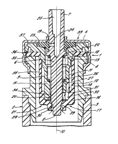
The valve 1 of Figure 1 is shown in
combination with a pressurised dispensing container 2
: 10 having a cylindrical container body 3. The valve 1
is held in place on a rim 4 of the container body 3
by means of a crimped valve ferrule 5.
A valv~ stem 6 has an outer end 7 which
projects from the valve 1 in an outward direction
with respect to the container body 3 and has an inner
end portion 8 projecting from the valve 1 in an
inward direction with respect to the container 2, the
valve 1 having a generally cylindrical body 9
defining an axis of symmetry 10 along which the stem
6 is reciprocatingly slidable,
: The valve body 9 has an external surface 11
which is stepped in diameter so as to progressively
decrease in size in the inward axial direction with
; respect to the container 2. A generally tubular
elastomeric sleeve 12 having a tubular sidPwall 38
coaxially overlays the body 9. The sleeve 12 fits
sealingly around an outer end 13 of the body 9.
: An annular shoulder portion 16 of the sleeve
12~is formed by a thickening of the sleeve material
: ~ 30 at the inner end 17 of the sidewall 38:such that the
sh~ulder portion extends radially inwardly with
respect to the axis 10 into contact with the inner
end 15 of the body. Because of the stepped taper of
; the external surface 11, an annular chamber I4 is
defined between the sleeve 12 and~the external
: : sur~ace intermediate tha outer end I3 and the inner
~:
~:
~L3~ 5
end 15 of the body. The shoulder portion 16 is
contoured to nestably receive the inner end 15 of the
body and in this way the sleeve 12 is positively
located in coaxial alignment with the body 9.
The annular chamber 14 is thereby closed at
its innermost end with respect to the container 2 by
the annular shoulder 16.
An internal chamber 18 is defined within the
body 9 and extends axial]y from an outlet aperture 19
through which the outer end 7 of the stem axtends and
an inlet aperture 20 through which the inner end
portion 8 of the stem extends. An outlet valve means
33 is formed in the outlet aperture 19 by a radially
outwardly projecting annular ~lange 22 of the stem 6
co-operating with an annular elastomeric seal 23
which is held in sealing contact with the body 9 by
the valve ferrule 5. A radially extending bore 24 of
the stem communicates with an axially extending
outlet channel 25 within the stem, the bore 24 being
disposed outside of the internal chamber 18 in the
closed condition of valve 1 as shown in Figure I in
which the position of the stem is such that the bore
is overlaid by the seal 23. The seal 23 not only
; prevents leakage of fluid from the internal chamber
18 around the stem 6 but also prevents the bore 24
from communicating directly with the atmosphere.
This prevents any deterioration of product fluid
tra~pped in the stem 6 when the apparatus is not in
use and also prevents leakage or drain back from the
stem on to the exterior of th~ ferrule 5. The stem
6 is biassed outwardly by a helical spring 26 held in
; ~ compression between~the stem flange 22 and a shoulder
27 formed in the internal chamber 18.
An inlet valve means 21 comprises a tubular
extension 28 of the sleeve l2 having a radially
~nwardly projecting rib 29 whlch is dimensioned to
~3~5~
provide a sealing fit around the stem 6. The inner
end portion 8 of the stem 6 i5 reduced in diameter
such that an annular opening 30 is formed between the
stem 6 and the rib 29 (and therefore the inlet valve
means 21 is in an open condition) when the valve 1 is
in a closed condition as shown in Figure 1.
An axially extending slot 31 is formed in the
inner end 15 of the body 9 and the slot extends
axially to a greater extent than the annular shoulder
portion 16 of the sleeve so as to communicate with
the annular chamber 14. The slot 31 has an inner end
: portion 32 which extends radially into communication
: with the internal chamber 18 at a location which is
adjacent to the inlet valve means 21. The internal
chamber 18 is of reduced diameter at this location
but axially extending spacer ribs 34 are provided
within the internal chamber 18 and project radially
inwardly to maintain clearance between the stem 6 and
; the internal chamber walls. The spacer ribs 34 also
serve to maintain the stem 6 in alignment with the
axis 10.
: : The sleeve 12 has at its outer end 35 a
radially outwardly Pxtending annular flange 36 which
serves as a gasket means between a radially outwardly
extending flange 37 of the body 9 and the rim 4 of
the container 2, The cylindrical sidewall 3~ of the
sleeve 12 extends between the flange 36 and the
; shoulder portion 16. The flange 36, the sidewall 38,
: : the shoulder 16 and the extension 28 including the
:~ ~ 30 rib ~9:are all integrally formed of an elastomeric
material which may be a natural or synthetic rubber
or may be a thermoplastic elastomer. The radial
thickness of the shoulder 16 is 1.4 millimetres
; compared with the much thinner thickness on the
extension 28 which is 0.5 millimetres. Consequently
the shoulder 16 is relati~ely rigid whereas the
~L3~Sl015
-- 7
extension 28 i5 relatively flexible. The rib 29
projects radially inwardly by 0.54 millimetres from
the extension 28. The radial thickness of the
sidewall 3~ is 0.55 millimetre so that the sidewall
is relatively flexible. This flexibility allows the
annular chamber 14 to be collapsible by radially
inward deformation of the sidewall 38. The rib 29 is
of semi circular cross section and in its relaxed
state has an internal diameter which is slightly less
than the diameter of the stem 6 but greater than ~he
diameter of the inner end portion 8~
Figure 2. shows the valve in the open
condition in which the stem 6 is depressed inwardly
with respect to the container 2 such that the bore 24
communicates with the internal chamber 18 to thereby
open the outlet valve means 33. In this condition
the depressed stem 6 makes sealing contact with the
rib 29 of the extension 28 such that the inlet valve
means 21 is in a closed condition. Penetration of
the stem through the rib 29 is accommodated ~y
resilient de~ormation of the extension 28.
In use the container body 3 is charged with a
pressurised fluid to be dispensed and once the valve
1 has been primed by an initial priming stroke of the
valve stem the internal chamber 18 and the annular
chamber 14 become filled;with fluid.
When the stem 6 is depressed inwardly with
respect to the container 2 such that the valve 1 is
in the open condition, the internal chamber 18 is
vented to atmospheric~ pressure and a ~low of fluid
commences from the internal chamber through the bore
24 to be dispensed through the outlet channel 25.
This reduction of pressure within the chamber 18 is
communicated through the slot 31 to the annular
chamber 14 so that a pressure differential is
; ~ established across the sidewall 38 which collapses
~3~L05
-- 8
radially inwardly towards the body 3 as shown in
Figure 2 thereby displacing fluid from the annular
chamber through the slot and into the intexnal
chamber 13. An equilibrium condition will then be
reached in which further deformation of the sidewall
38 is prevented by contact with the body 3 and the
flow of fluid is arrested. The valve stem is then
released and returns under spring pressure to its
normal position as shown in Figure 1 and in doing so
closes the outlet valve means 33 and opens the inlet
valve means 21. The sleeve sidewall 38 then relaxes
to its cylindrical undeformed shape and in doing so
creates suction within the annular chamber 14. A
refill flowpath is at the same time established from
within the container 2, through the annular opening
30 around inner end portion 8 of the stem 6, into the
internal chamber 18 at a location adjacent to the
inlet valve means 21 and through the slot 31 to
recharge the annular chamber 14 with fluid. An
equilibrium condition will then be reached in which
pressure is equalised on either side of the sidewall
38 and the refill flow ceases. The valve is then
ready for further actuation.
It has been found that during repeated
actuation of the valve 1, the quantity of fluid
dispensed at each actua~ion remains substantially
constant. By adjusting the dimensions of the annular
chamber 14 it is possible to adjust the dispensed
~quantity so that a predetermined metered dose is
dispensable.
~;~ Alternative embodiments of the invention are
envisaged in which the seal 23 of the outlet valve
means 33 comprises a double seat arrangement (not
shown) in which two axially spaced valve seats are
integrally formed in a sealing component. Suah an
~arrangement provides additional protection against
~L3(~5~1L05
external contamination of the product.
The valve has application in pressurised
dispensing containers which are rec~uired to operate
at any orientation since the metered c~uantity
dispensed is independent of valve orientation. The
valve therefore has particular application to
dispensers for nasal administration o~ medicinal
products.
:: :
: ~
:
:: :
~ : 25 ; ~ ; ~
: ~ :
:
:: : ~ : : :
: ~ : : : `
~ 30 ~ :
: ~ ` :
:: :
~ 35 ~
: :
.