Note : Les descriptions sont présentées dans la langue officielle dans laquelle elles ont été soumises.
-
DOOR HOLDING DEVICE
BACKGROUND OF THE INVENTION
lo Field of the Invention
The present invention relates to a door holding device,
particularly for motor vehicle doors. The door holding device
: includes a door holding rod which is swivelably attached to a
structural door component, a door or a door post. The door
holding rod extends with its other end through a holder housing
mounted on another structural door component or the like. The
~ door holding rod has along its length increased diameter portions
- : which protrude outwardly transversely of the longitudinal
~1 :
~ : direction of the door holding rod. The door holding rod is
. ~
; freely swivelably mounted on a carrier member by means of a
clinch bolt or a screw bolt. The carrier member is formed by
`:~ a single shaped piece and is attached to one of the structural
,:
~ ~ door components.
:;,:
~ 2. Description of ~he Prior Art
, :.
~:: Door holding devices of the above-described type are
~: known. In the known door holding devices, the carrier member
supporting the swivel bearing of the:door holding rod is formed
by a blank of flat material which has been twisted by 90. Thus,
`~ the carrier member lS made of a single-piece material blank in
1~; a punching and shaping procedure, The carrier member has a
.
.` ~
stiffness which is sufficient for a secure support of the
swivel bearing of the door holding rod.
However, the carrier member of the known door holding
device has the disadvantage that for ensuring a sufficient
stiffness a relatively thick initial material must be used. The
natural stiffness of this initial materiaL is additionally
reduced because the necessary cut for punching out the blank
leads to a disturbance of the existing pattern of the fibers of
the material, so that an even greater thickness of the initial
material must be used as would be required for the actually
necessary stiffness. This leads to an undesirable increase of
the manufacturing costs and to an also undesirable increase in
the weight of the door holding device.
Although the carrier member of the swivel bearing for
the door holding rod in the known door holding device is simple
to manufacture, the carrier member has the further disadvantage
that it provides only in$ufficient safety with respect to a
rotation o~ the bearing pin for the door holding rod and that
its fastening to the structural door component, the door or the
door pQSt is not absoluteIy reliable because it is secured only
by surface pressure.
: :
~ In devices for supporting door holding rods on the
.:
- carrier members or support members, it is further known to avoid
play between the bearing opening in the door holding rod and the
bearing pin extending throug~ the bearing hole by providing the
bearing pin with~a deformabIe surface profiling. Specifically,
it has been proposed to equip the bearing pin with an axially
--2--
, . . .
directed clrcumferentlal milling. This milling deforms when the
bearing pin is driven in and, thus, ensures a support of the door
holdlng rod which is absolutely free of play. As a result, even
after long term use, no rattling noises can ~e caused by sudden
loads on the bearing by the passage through the holder housing of
the increased thickness portions of the door holding rod.
However, obtaining the play-free support of the door holding rod
by means of an axially directed clrcumferential milll~g has no~
been *ound fully satisfactory because the parallel profillngs of
a circumferential milling can still lead to a sudden passage of
the increased thickness portions of the door holding rod through
the holder housing.
The present in~ention improves a door holding device of the
aforedescribed type, so that the manufacturing costs and the
weight o~ the door holding device are reduced. The forces
resulting from the manner of operation of the door holdlng device
are to be absolutely securely supported. In addition, a
completely noise-free operatlon of the device is desired even
: during long-term oper~tion. Finally, an optimum shape of the
structural components ls to be achiev~d.
According to the present invention there is provided a door
holding device for motor vehicle doors, comprising a door holding
: rod having first and second ends, a carrier member h~ving a
cantilevered portion attached to a structural door compo~ent, the
first end of the door holding rod freely swivelably connected the
: cantilevered portion of the carrier member r the second end of the
door holding rod extending through a holder housing mounted on
another structural door component, door or door post, the door
holding rod having along its length i~creased thickness portlons
protruding outwardly transversely of the longitudinal direction
of the door holding rod, the door holding rod and the carrier
member defining openings, a bolt extending through the opening of
the door holding rod and o~ the carrier member, so that the door
holding rod is freely swlvelable relative to the bolt, while the
- 3 -
.,
.,
55~3~
carrier member is non-rotatable relative to the bolt, the carrier
member formed by a single shaped piece, the bolt having a head, a
spring mounted between the head of the bolt and the door holding
rod, the bolt having a shaft portion, the shat portion of the
bolt defining a deformable surface profiling on the lenyth of the
bolt extending through the opening of the door holding rod,
wherein the surface profiling ensures a play-free mounting of the
bolt in the opening of ths door holding rod.
In accordance with the present invention, a sprlng load is
applied to the door holding xod ~n axial direction of the swivel
bearing of the door holding rod, wherein the spring rests against
the head o the clinch bolt or screw bolt. The
:
~: - 3a -
. 't
' ~ ~ ' ' ''
., ;
5~
clinch bolt or screw bolt is mounted secured against rotation
in the opening of the carrier member~ The clinch bolt or
screw bol-t additionally has a knurled profiling in engagement
with the opening of the door holder rod, the knurled profiling
ensuring an engagement which is free of play and secured against
sudden rotation and also providing a bed for a supply of
lubricant.
In accordance with another feature of the present
invention, the carrier member is made from a portion of a
round material as the initial material. The two ends of this
round blank are then pressed or squeezed into two end faces
extending perpendicularly to each other. A door closing
device including such a carrier member has a very low weight
and a sufflcient stiffness, and can be manufactured in a very
simple manner. In addition, it is ensured that even after long
i
term use no noise lS generated within the support of the door
holding rod. Moreover, the entire device can be assembled in a
very simple manner.
In accordance ~ith ~nother embodiment of the invention,
the $pxing resting against the head of the clinch bolt or screw
balt is a spring washer or plate spring. The clinch bolt or
; .
screw bolt forms over a part of its length the swivel bearlng
of the door holding rod. In order to ensure that the clinch
~- bolt or screw bolt does` not rotate rel`ati~e to the carrier
member, the opening of the carrier member has a cross-sectional
~; shape which coincides with the cross-sectional shape of the
.
coxresponding portion of the`clinch bolt or screw bolt. Thi~
cross-sectional shape is different from the circular shape and
may particularly by polygonal or ovalO
~s~
In accordance wi~h another feature of the present
invention, the shaft of the clinch bolt or screw bolt may over
the portion of its length which supports the door holding rod
have a greater diameter than in the portion of its length where
it is engaged by the carrier me~ber.
In accordance with yet another advantageous feature
of the invention, the opening of the carrier which engages the
aforementioned shaft portion of the clinch bolt or screw bolt
may have a conical shape at least over a portion of its depth,.
so that the thickness of the bolt shaft increases during
riveting, thereby resulting in a further securing of the bearing.
For securely fas.tening the carrier member to the
respective structural door component, it is further provided
that the surface of the carrier me~ber resting against the
structural door component hàs anchoring means which projects
above the plane of the s:urface, such~as, claws or similar
profilings,~so that when the carrier member is mounted, a
mech~nical connection between the carrier member surface and
the corresponding structural door component is automatically
effected.
:
The various features of novelty which characterize
the invention are pointed out with paxticularity in the claims
annexed to and forming a part of this disclosure. For a better
understanding of the invention, its operating advantages and
specifi.c obj:ects attained by its use, reference should be had
to the drawings and descripti~e matter in which there is
illus.trated and described a preferred embodiment of the
invention.
_5_
,
,
BRIEF DESCRIP~ION OF THE DRAWINGS
In the drawings:
Fig. 1 is a side elevational view of a door holding
device according to the present inven~ion;
Fig. 2 is a front elevational view of the door
holding device of Fig. l;
Fig. 3 is a partial sectional view, on a larger scale,
taken along sectional line A - B of Fig. 2;
:
Fig. 4 is an enlarged view of a carrier member forming
part of the door holding device shown in Fig. l; another
possible shape of the carrier member i5 illustrated in broken
lines;
Fig. 5 is a front view of the carrier member shown
in Fig, 4,
` ~`
;,
Fig. 6 is a t~p view of the carrier member shown in
~Flg 4~ and
Fig. 7~is a bottom view of the carrier member shown in
Fig. 4.
,~
-6~
.
DETAILED DESCRIPT ON OF THE PRESENT INVENTION
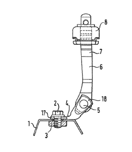
As illustrated in Fiy. l, a carrier member 4 for
the swivel bearing 5 of a door holding rod 6 is attached to a
structural door component 1 by means of a screw bolt 2 and a
nut 3. Theother end of door holding rod 6 extends through a
holder housing 8 which is part of a second structural door
component, noti shown. The door holding rod 6 has increased
thickness portions 7.
The swivel bearing 5 may be formed by a clinch bolt
or a screw bolt. In the illustrated embodiment, the swivel
bearing 5 is a clinch bolt 9 which includes a head 10, a fi.rst
shaft portion 11, a second shaft portion 12 and a clinched
part 13.
As particularly illustrated in Fig. 3, the two shaft
portions ll and 12 of the':clinch'bolt 9 have different diameters.
The door holdlng rod 6 is mounted on the snaft portion ll having
.
,:~the. greater diameter. The periphery of the shaft portion ll :'
of clinch bolt 9 has a knurled profiling~ i,e., a criss-cross
surface profiling wh:ich:'permits the inclusion of a supply of
i:
,~: lubricant and prevents the''$ormation of chatter marks in the
,,opening of the door holding rod. Also, this surface profiling
ensures that the door holding device operates permanently
without play and without noise.
me shaft portion 12 of clinch bolt 9 engaged by the
opening 14 of carrier memker 4 has an axially directed
:~,
.
, -7-
,
circumferential milling. In addition, along its length engaged
by the opening of the carrier member 4, the clinch bolt 9 has
a cross-sectional shape which deviates from the circular shape.
The opening of the carrier member 4 has a cross-sectional shape
15 which corresponds to that of the just described shaft portion.
;
Carrier member 4 is manufactured from a portion of
round material. The two end areas of -the carrier member 4
define end faces 17 and 18 which extend perpendicularly to each
other. The end areas of the carrier member 4 are formed by
pressing or squeezing the material.
As can be seen from Figs. 4, 5 and 7, the end face 17
may be provided ~ith indentations or projections which form
claws 19. Fig. 4 further shbws that the overall shape of the
carrier member4 may be straight or angular. The angle of the
carrier member 4 ~ay vary within the range of from 0 to 90.
Perpendicularly to the swivel bearing of the door
`hQlding ~od 6 by means of the clinch bolt 9, a spring load is
applied to the~door holding rod 6. As illustrated in Fig. 3,
the sprin~ lo~ad may be applied by a spring washer 21 placed
bet~een the head lO~of clinch bclt 9 and the door holding rod 6.
:: ~
:
~ hile a specific embbdiment of the invention has been
sho~n and described in detail to illustrate the application of
the inventive principles, it will be understood that the invention
may be embodied otherwlse without departing from such principles.