Sélection de la langue

Search

Sommaire du brevet 1306848 

Énoncé de désistement de responsabilité concernant l'information provenant de tiers

Une partie des informations de ce site Web a été fournie par des sources externes. Le gouvernement du Canada n'assume aucune responsabilité concernant la précision, l'actualité ou la fiabilité des informations fournies par les sources externes. Les utilisateurs qui désirent employer cette information devraient consulter directement la source des informations. Le contenu fourni par les sources externes n'est pas assujetti aux exigences sur les langues officielles, la protection des renseignements personnels et l'accessibilité.

Disponibilité de l'Abrégé et des Revendications

L'apparition de différences dans le texte et l'image des Revendications et de l'Abrégé dépend du moment auquel le document est publié. Les textes des Revendications et de l'Abrégé sont affichés :

  • lorsque la demande peut être examinée par le public;
  • lorsque le brevet est émis (délivrance).
(12) Brevet: (11) CA 1306848
(21) Numéro de la demande: 566890
(54) Titre français: REACTEURS DESTINES A LA SYNTHESE HETEROGENE
(54) Titre anglais: REACTORS FOR HETEROGENEOUS SYNTHESIS
Statut: Réputé périmé
Données bibliographiques
(52) Classification canadienne des brevets (CCB):
  • 23/425
(51) Classification internationale des brevets (CIB):
  • B01J 15/00 (2006.01)
  • B01J 8/04 (2006.01)
(72) Inventeurs :
  • ZARDI, UMBERTO (Suisse)
  • PAGANI, GIORGIO (Suisse)
(73) Titulaires :
  • AMMONIA CASALE S.A. (Suisse)
(71) Demandeurs :
(74) Agent: MITCHES & CO.
(74) Co-agent:
(45) Délivré: 1992-09-01
(22) Date de dépôt: 1988-05-16
Licence disponible: S.O.
(25) Langue des documents déposés: Anglais

Traité de coopération en matière de brevets (PCT): Non

(30) Données de priorité de la demande:
Numéro de la demande Pays / territoire Date
01846/87-5 Suisse 1987-05-14

Abrégés

Abrégé anglais


ABSTRACT

In reactors for heterogeneous synthesis, comprising a boiler
and a heat exchanger inserted at least partially into the end
catalytic beds, and at least an intermediate catalytic bed,
two airspaces are now provided in each catalytic bed by
introducing couples of annular walls, one of said airspaces
being produced between the cartridge's internal wall and the
perforated wall inserted close to it.

Revendications

Note : Les revendications sont présentées dans la langue officielle dans laquelle elles ont été soumises.


The embodiments of the invention in which an exclusive
property or privilege is claimed are defined as follows:
1. A system to increase reactor yield of a reactor for
heterogeneous synthesis which includes an internal boiler and
an internal heat exchanger inserted at least partially into a
catalytic layer comprising:
(a) a first catalytic layer, the first catalytic layer
being partly connected to a boiler;
(b) a second catalytic layer, the second catalytic
layer being partly connected to a heat exchanger;
(c) at least one intermediate catalytic layer disposed
between the first catalytic layer and the second catalytic
layer;
(d) each catalytic layer having an internal annular
wall and an external annular wall for defining a first
airspace and a second airspace for each catalytic layer, the
internal annular wall and external annular wall of each
catalyst layer being at least partially perforated;
(e) the external annular wall of the first catalytic
layer being perforated along an entire length thereof, the
first airspace of the first catalytic layer being defined by
the perforated external wall of the first catalytic layer and
a cartridge wall of the reactor;
(f) the internal annular wall of the first catalytic
layer being perforated along a length less than the length of
the external annular wall of the first catalytic layer, the
second airspace of the first catalytic layer being defined by
the perforated internal annular wall of the first catalytic
layer and a wall of the boiler;
(g) the external annular wall of the second catalytic
layer being perforated along an entire length thereof, the
first airspace of the second catalytic layer being defined by
the perforated external annular wall of the second catalytic
layer and the cartridge wall of the reactor;
(h) the internal annular wall of the second catalytic
layer being perforated along a length less than the length of
the external annular wall of the second catalytic layer, the


second airspace of the second catalytic layer being defined
by the perforated internal annualar wall of the second
catalyst layer and a wall of the heat exchanger;

2. The system of claim 1, wherein a minor unperforated
portion of the internal annular wall of the first catalytic
layer comprises a portion of the wall of the boiler.

3. The system of claim 1, wherein a minor unperforated
portion of the internal annular wall of the second catalytic
layer comprises a portion of the wall of the heat exchanger.

4. The system of claim 1, wherein the internal annular
wall of the at least one intermediate catalytic layer is
perforated along an entire length thereof, the first airspace
of the at least one intermediate catalytic layer being
defined by the internal annular wall of the at least one
intermediate catalytic layer, the external annular wall of
the at least one intermediate catalytic layer being
perforated along a length less than the internal annular wall
of the at least one intermediate catalytic layer, the second
airspace of the at least one intermediate catalytic layer
being defined by the perforated external wall of the at least
one intermediate catalytic layer and the cartridge wall of
the reactor.

5. The system according to claim 1, wherein gas flows
through the first catalytic layer, the second catalytic layer
and the at least one intermediate catalytic layer in an
axial-radial flow pattern.

Description

Note : Les descriptions sont présentées dans la langue officielle dans laquelle elles ont été soumises.


DESCRIPTION
___________

This invention concerns the improvements made to reactors for
heterogeneous synthesis. It concerns more particularly a
system to increase the yields of reactors for heterogeneous
synthesis and more particularly for the synthesis of ammonia,
comprising a catalytic layer partly connected to a boiler, a
catalytic layer substantially run through by a heat
exchanger, and at least one intermediate catalytic layer.


Reactors of the type described above are known per se and are
the object of Italian patent No. 28961-66.


In order to establish matters straight away and to ma~e it as
easy as possible to understand the invention, Figure
(partial cross-section with a plan showing the reactor's
axis) outlines a reactor design according to the patent in
question.


The synthesis gas GS enters from 10, flows from top to bottom
through airspace 21 between the internal wall 22 of the shell
M and the external wall 23 of the cartridge CU, flows upwards
from the bottom FO (following arrow F1) running through the
inside of tubes Ti of the heat exchanger SC, flows axially
(arrow F2) through the intermediate catalytic layer CC, is
cooled in the first branch of the boiler CA from the top of
which it leaves in order to penetrate (arrow F3) the top


~' I


catalytic layer CS, t~rough which it runs axially from top to
bottom leaving according to arrow F4 and flowing again
upwards as ~'4 which enters tube sP which takes it as ~low F5
directly into the lower catalytic layer CI from which it
flows as F ' 5 to continue upwards inside exchanger Sc from the
top of which it is sent downwards as F7 flowing through
central tube 25' and leaving this as reacted gas F'7.
Arrow F8 indicates the conduction of water to the boiler and
arrow F9 indicates the exit from the boiler of the vapour
produced therein by recovering reaction heat. Since the
reactor in question is known it is not described in detail
herein, such description belng available in the above-
mentioned Italian patent No. 28961-66.


Reactors of the type déscribed above, although already
remarkably improved when compared to the technology available
up to the moment when they made their appearance, suffered
from a nu~ber of disadvantages which in the long run became
an obstacle to the success which it seemed reasonable to
expect from them.


Among the disadvantages in quéstion, mention should be made
in particular of those connected with the axial flow of the
synthesis gas through the catalytic beds, of the ensuing
pressure drops and of the need to use a large size catalyst
in order to limit the pressure drop in question.


characterized by the fact that in the intermediate calalytic
layers unconnectd to the boiler or to the heat exchanger, the
annular wall forming an airspace with the cartridge is the
external one and is perforated along a shorter length than
the annular internal wall, the cylindrical space inside said
annular wall with the greater perforated length being free
from catalyst, constituting the second airspace.
The invention obviously comprises the reactors as
obtained with the system in question.
The invention will now be described by way of example
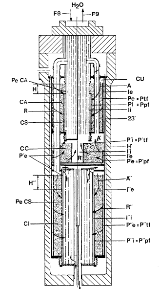
and reference to the accompanying drawings in which:
Figure 1 shows a cross-sectional view of a known
reactor.
Figure 2 shows a cross-sectional view of a reactor in
accordance with the invention.
A preferred but not limitative embodiment of the
invention is shown in Figure 2, which is a longitudinal
partial cross-section, similar to that in Figure 1, of a
reactor converted from being totally axial to being
substantially radial.
According to a first aspect of the invention, two
airspaces are created in each catalytic bed, one of these,
i.e., still the external one Ie, I'e, I"e, always involves
the internal wall 23' of the cartridge CU. In ePfect the
annular external walls Pe, P'e, P"e are introduced into the
three beds to form said external airspaces Ie, I'e, I"e with
23'. Into the same beds are introduced annular internal
walls Pi,P'i, P"i which form the internal airspaces Ii, I'i,
I"i.
According to an aspect of the invention, in the two end
beds connected to the boiler ~top bed CS) and to the heat
exchanger (bottom bed CI), the external walls Pe and P"e are
totally perforated so that Pe = Ptf and P"e = P"tf (where Ptf
stands for totally perforated wall). The corresponding
internal wall Pi and P"i are unperforated for a minor portion
H, respectively H". Preferably, the unperforated section H
consists of the boiler's external wall Pe CA. In the bottom
bed CI too, the unperforated wall H" can be the external wall


Pe CS of the heat exchanger. Preferably however, the sectlon
H" is the unperforated continuation of internal wall Pi"
which coincides therefore with the partly perforated wall
P"pf (pf = partly perforated).
According-to another aspect of the invention, an
external annular wall P' unperforated along section H' is
introduced into the intermediate bed, said section H' being
formed by the solid wall 23' of the cartridge. The internal
annular wall P'i is perforated for its total length,
therefore P'i = P'tf. The cylindrical wall inside P'i, i.e.,
the internal airspace I'i, is now empty, i.e., not filled
with catalyst.
By arranging in each bed a totally perforated wall
accompanied by a partially perforated wall the axial flow A,
A', can be achieved, respectively A", in the minor
unperforated portions H, H', respectively H", and a radial
flow in the remaining major perforated portions in the single
beds.
Thanks to this , it is now possible to use a small-
size catalyst thus reducing further pressure drop and
increasing yields.
The applicants have in effect already described in a
series of preceding patents and patent applications, the
advance technology of their axial-radial reactors; see in
particular, U.S.A. Patent No. 4,372,920.
Dessin représentatif
Une figure unique qui représente un dessin illustrant l'invention.
États administratifs

Pour une meilleure compréhension de l'état de la demande ou brevet qui figure sur cette page, la rubrique Mise en garde , et les descriptions de Brevet , États administratifs , Taxes périodiques et Historique des paiements devraient être consultées.

États administratifs

Titre Date
Date de délivrance prévu 1992-09-01
(22) Dépôt 1988-05-16
(45) Délivré 1992-09-01
Réputé périmé 1998-09-01

Historique d'abandonnement

Il n'y a pas d'historique d'abandonnement

Historique des paiements

Type de taxes Anniversaire Échéance Montant payé Date payée
Le dépôt d'une demande de brevet 0,00 $ 1988-05-16
Enregistrement de documents 0,00 $ 1988-09-16
Taxe de maintien en état - brevet - ancienne loi 2 1994-09-01 100,00 $ 1994-08-11
Taxe de maintien en état - brevet - ancienne loi 3 1995-09-01 100,00 $ 1995-08-10
Taxe de maintien en état - brevet - ancienne loi 4 1996-09-02 100,00 $ 1996-08-19
Titulaires au dossier

Les titulaires actuels et antérieures au dossier sont affichés en ordre alphabétique.

Titulaires actuels au dossier
AMMONIA CASALE S.A.
Titulaires antérieures au dossier
PAGANI, GIORGIO
ZARDI, UMBERTO
Les propriétaires antérieurs qui ne figurent pas dans la liste des « Propriétaires au dossier » apparaîtront dans d'autres documents au dossier.
Documents

Pour visionner les fichiers sélectionnés, entrer le code reCAPTCHA :


Pour visualiser une image, cliquer sur un lien dans la colonne description du document. Pour télécharger l'image (les images), cliquer l'une ou plusieurs cases à cocher dans la première colonne et ensuite cliquer sur le bouton "Télécharger sélection en format PDF (archive Zip)" ou le bouton "Télécharger sélection (en un fichier PDF fusionné)".

Liste des documents de brevet publiés et non publiés sur la BDBC .

Si vous avez des difficultés à accéder au contenu, veuillez communiquer avec le Centre de services à la clientèle au 1-866-997-1936, ou envoyer un courriel au Centre de service à la clientèle de l'OPIC.


Description du
Document 
Date
(yyyy-mm-dd) 
Nombre de pages   Taille de l'image (Ko) 
Dessins représentatifs 2000-07-31 1 35
Description 1993-11-04 4 138
Dessins 1993-11-04 2 78
Revendications 1993-11-04 2 82
Abrégé 1993-11-04 1 13
Page couverture 1993-11-04 1 12
Taxes 1996-08-19 1 33
Taxes 1995-08-10 1 32
Taxes 1994-08-11 1 34