Note : Les descriptions sont présentées dans la langue officielle dans laquelle elles ont été soumises.
1 3(~547
The invention relates to a shaving apparatus having a
housing with a holder for a flexible cutting plate and a cutting
member which can be driven rotatably with respect to the cutting
plate and has rigid cutting elements, said cutting elements
comprising cutting sides at the radial ends.
In order to obtain a good shaving result it is of
importance for the cutting plate to readily adjoin the cutting
member. In a known construction as is described in French Pa~ent
Specification 994 890 this is obtained by pulling the cutting
plate against the cutting member by means of a resilient element.
However, the larger the forces between the cutting member and the
cutting plate the larger will be the frictional losses and the
detrition.
It is known from French Paten~ Specification 1 050 751
to stretch the flexible cutting plate over wall parts of the
holder. In practlce, however, it is difficult to manufacture the
holder which is usually of a synthetic resin with a sufficient
accuracy so that differences in shape will occur between the
cutting plate and the cutting member which will adversely
influence the shaving result.
According to one broad aspect, the present invention
provides a shavlng apparatus having a houslng with a holder for a
flexible cu~ting plate and a cutting member which can be driven so
as to be rotatable with respect to the cutting plate comprising a
shaft and rigid cutting elements with radial ends, the cutting
elements comprising cutting sldes at the radial ends, and wherein
the cutting plate is stretched over individual supporting disks
provided on each side of the cutting member, the shaft being
~ournalled in the holder and in the individual supporting disks.
According to another broad aspect, the present invention
provides a shaving apparatus having a housing with a holder for a
flexible cutting plate and a cutting member which can be driven so
as to be rotatable with respect to the cutting plate comprising a
shaft and rigid cutting elements with radial ends and wherein the
cutting plate is provided with individual supporting disks, the
shaft being journalled in the holder and in the individual
1 30~547
supporting disks, at leas~ one supporting disk comprising a slot
containing a compression spring compressed between the shaft and
the holder.
According to a further broad aspect, the present
invention provides a shaving apparatus having a housing with a
holder for a ~lexible cutting plate and a cutting member which can
be driven so as to be rotatable with respect to the cutting plate
comprising a shaft and rigid cutting elements with radial ends and
wherein the cutting p]ate is provided with individual supporting
disks, the shaft being journalled in the holder and in the
individual supporting disks, the individual supportlng disks being
supported by a resilient element stretched between the supporting
disk and a support of the holder, each supporting disk comprising
a slot whereby it is movable in a direction perpendicular to the
shaft.
The invention will now be described in greater detail
with reference to a description of an embodiment shown in the
Figures.
Figure 1 i5 a diagrammatic longltudinal sectional view
of a shaving apparatus according to the invention.
Figure 2 is partly a sectional view taken on the line
II-II of Figure 1 and partly an elevation.
Figures 3, 4 and 5 show three special embodiments in
1 3n~547
a detail of a sectional view in accordance with Figure 1.
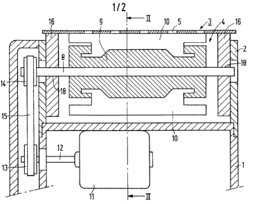
The shaving apparatus shown in Figures 1 and 2
comprises a housing 1 having a holder 2 for a flexible
cutting plate 3 and a cutting member 4 which can be driven so
5 as to be rotatable with respect to the cutting plate.
The cutting plate 3 comprises hair entrance
apertures 5 and also comprises a first and a second edge
portion 6 and 7, respectively, with which the cutting plate
is connected to the holder 2.
0 The cutting member 4 comprises the shaft 8, the hub
9 and the cutting elements 10. The shaft 8 and the cutting
elements 10 are placed, for example, in the matrix for the
hub to be manufactured from a synthetic resin and by means of
an injection moulding process so that after curing of the
15 synthetic resin the shaft 8, the hub 9 and the cutting
elements 10 form one rigid assembly.
The shaft 8 is journalled in the holder 2 so as to
be rotatable and is driven by the electric motor 11. On the
shaft 12 of the electric motor and on the shaft 8 the pulleys
20 13 and 1g, respectively, are provided which are coupled by
means of the belt 15. In this manner the cutting member 4 can
be driven so as to be rotatable with respect to the cutting
plate 3, for example, in a direction indicated by the arrow
P. When the shaving apparatus is moved over the skin to be
25 shaved, a hair which projects inwardly through a hair
entrance aperture 5 will be cut as a result of the co-
operation of the cutting plate 3 and a cutting edge 10' of a
cutting element 10.
The shaft 8 is journalled in two individual
30 supporting disks 16 on each side of the cutting member 4.
These individ~al supporting disks may already be placed on
the shaft 8 in the final phase of the manufacture of the
cutting member 4 and be ground simultaneously with the
cutting member 4 so that cutting member 4 and supporting
35 disks 16 have exactly the same diameters. During assembly of
the cutting member 4 in the holder 2 the supporting disks 16
are then connected to the walls of the holder 2 by means of
1 3~)~547
known connection methods, for example, with screw bolts or by
means of a gluing, welding or riveting process. The cutting
plate 3 is then stretched over the supporting disks 16 by
means of a resilient element 17. The part of the cutting
5 plate 3 formed by the supporting disks 16 is bent in this
manner according to a cylinder surface which corresponds
exactly with the imaginary cylinder surface on which the
cutting edges 10' of the cutting elements 10 are situated.
The accuracy with which the cutting member 4 engages the
cutting plate 3 is hence determined by the accuracy of the
grinding process with which cutting member 4 and supporting
disks 16 are ground simultaneously and by the accuracy with
which the shaft 6 is journalled in the bores 18 of the
supporting disks 16. The relevant manufacturing methods can
also be performed in a series-production process in a
comparatively simple manner and with a high degree of
accuracy. The tensile force exerted on the cutting plate 3 by
the resilient element 17 is compensated by the supporting
disks 16 so that in principle no pressure forces need occur
20 between the cutting plate 3 and the cutting member 4. The
play between the cutting member 4 and the cutting plate 3 is
in principle determined by the play of the shaft 8 in the
bores 18. In this manner a light running cutting member 4 is
obtained having no frictional losses and a low detrition
25 while an effective shaving effect is nevertheless ensured.
Figures 3, 4 and 5 show modified embodiments of the
constructions shown in Figures 1 and 2 in a detail which
corresponds to the right hand side of the cross-sectional
view of Figure 1. These modified embodiments relate to the
30 construction of the supporting disks 16 and the bearing of
the end of the shaft 8 and are constructed in a corresponding
manner for each construction on the left-hand side of the
cutting member 4.
In the Figure 3 embodiment the supporting disk 16
35 which is again rigidly connected to the holder comprises a
slot 19. The compression spring 20 which is compressed
between the shaft 8 and a support 21 which forms part of the
1 3(~547
holder 2 is present in the slot 19. In this manner the
cutting member 4 can be moved against the action of the
resilient elements 20 with respect to the supporting disks 16
in the direction of the~arrow Q. The advantages of the
5 embodiment shown in Figures 1 and 2 are also maintained in
this embodiment. However, when too high a force is exerted on
the cutting member 4 via the cutting plate 3, the cutting
member 4 can deviate against the action of the resilient
elements 20 so that damage can be prevented.
In the Figure 4 embodiment the shaft 8 of the
cutting member is journalled in the holder 2. The supporting
disk 16 is not connected to the holder 2 and comprises a
slotted hole 22 so that the supporting disk can be moved in
the directions R with respect to the shaft 8. The supporting
lS disk 16 is supported by a resilient element 23 which is
stretched between the supporting disk and a support 24 of the
holder 2. The magnitude of the forces occurring between the
cutting plate 3 and the cutting member 4 can now be adjusted
accurately in a simple manner during the manufacture
20 dependent on the resilient elements 17 and 23.
In the Figure 5 embodiment the shaft 8 is also
journalled in the holder 2. The supporting disk 16 is not
connected to the holder 2 and is journalled so as to be
rotatable on the shaft 8. Starting from exactly the same
25 diameters of supporting disk 16 and cutting member 4 the
cutting plate 3 will initially be supported substantially by
the cutting member 4 as a result of a slight play in the
bearing between the supportinq disk 16 and the shaft 8.
However, after the apparatus has run in and the diameter of
30 the cutting member 4 has been reduced slightly by detrition,
it can be achieved in this manner that the cutting plate 3 is
supported substantially by the supporting disks 16, the
cutting plate 3 very readily adjoining the cutting member 4.