Note : Les descriptions sont présentées dans la langue officielle dans laquelle elles ont été soumises.
6~1~
--1--
POLYMER FILTRATION APPARAT~
Br;ef Sununary of the Inv~ntion
This invention relates generally to polymer
filtration ~stems that ronDect between plastic
5 extruders and plastic formincl or processing
apparatus, typically dies. More particularly, the
invention relates to apparatus for supporting
filtra~ion screens in the polymer flo~ pa~h, and for
changing the screens when they become occluded by
10 foreign particles or solid lumps of the pol~mer.
A simplified polymer filtration system
comprises a single polymer 10w passage with a single
slide member movable across the passage for locating
a replaceable filter therein. In such a system the
15 flow passage is temporarily blocked by the slide
member when it is shifted to a position in which the
filter is esternal to the body of the apparatus. The
loss of downstream polymer pressur , or even a sudden
reduction in such pressure, typically seriously
20 impairs the operation ~f downstream polymer
processing apparatus. Therefore, various schemes
have be~n proposed ~or maintaining polymer pr~ssure
during the ehanging of filters.
U.S. Patent No. 4,167,384 to Shirato et al
25 discloses polymer filtration apparatus having an
inlet that diverges into ~irst and second upstream
passages, with first and second downstream passages
~`
~L3~ 2
--2--
converging to an outlet. A pair of parallel ~lide
plates are provided, one between each upstream
passage and a corresponding downstream passage. For
changing a filter screen, only a single slide plate
5 is shifted at a time, whereby the other sli~e plate
remains in its active position, allowing its filter
to sustain polymer pressure by permitting continued
flow to the outlet. The provision of two completely
~eparate slide plates in corresponding slide channels
10 in the body of the apparatus results in comple~ity of
structure with corresponding espense and difficulty
of repair and maintenance.
According to a variation in the Shirato
configuration, each of the two slide members supports
15 a pair of screens, whereby one screen is located ~on
line~ or ~in normal active position, R that is, in a
position fully aligned with and communicatin~ between
an upstream flow passaqe and a downstream flow
- passage, when the other screen has been shifted to a
20 position e~terior to the body. In one form, this is
accomplished by providing ~our mutually connected
upstream polymer flow passages and four corresponding
mutually connected downstream polymer flow passages.
These arran~ements result in even greater complexity
25 of apparatus~
U.~. Patent No. 4,395,212 to Lambertus
discloses a screen changer haviny a
pair of upstream flow passages and a corresponding
pair of downstream flow passages, with a single slide
30 member havinq two apertures for replaceable screen
filter~. The æhifting of either filter to a posit;on
external to the body of the apparatus simultaneously
shifts the other filter from alignment with one pair
of upstream and downstream passages to similar
, ~ .
~3~D~$~2
alignment with the other pair of passages. The
e~tent of the channel surfaces between the pairs of
passages is less than the extent of each of the
filter apertures in the slide member, so that
5 throughout the movement of the slide member to
replace either filter at lea~st one of the filters is
at least partially located in the flow passa~e of the
filter being replaced. Thus polymer flow is not
completely blocked at any time during the movement of
10 the slide member. However, lthe Lambertus arrangement
has the inherent disadvantage that during a portion
of the movement of the slide rnember, one of its
filter apertures is in direct communication between a
flow passage and the e~terior of the apparatus. This
15 causes polymer leakage and a severe drop in the
pol~mer pressure, the latter being a particular
disadvantage when the system pressure is normally at
elsvated levels, for example 5,000 p.s.i. The
consequent pressure drop is communicated downstream
20 to processing apparatus, and may seriously affect its
performance. A further disadvantage is that the
slide member must be moved suddenly between the
normal position and each of the filter changing
positions, eliminating the possibility of prefilling
25 a newly replaced filter in an intermediate position
to e~pel the air within the filter aperture before
the filter is inserted in the normal active position.
With a view to overcoming the foregoing and
other disadvantages inherent in prior art screen
- 30 changers, one of the objects of this invention is to
provide polymer filtration apparatlls of simple
construction in which there is continuous polymer
flow at all times and in all positions of the filter
changing ~echanism, and which provides easy access to
35 the filter elements for replacement.
.
~3g~
A second object is to provide polymer
filtration apparatus in which the fiIter apertures in
the slide member do not provide direct leakage paths
from the flow passages to the e~erior of the
5 apparatus in any position of the slide member.
The achievement of t:he foregoing objects,
according to this invention, results from an
improvement embodied in a structure having a single
slide member with two filters and two pairs of
10 polymer flow passages. The climensions of the fil~er
apertures are related not only to the channel surface
dimensions between the pairs of passages, but also to
the estents of the channel sealing surfaces of the
body between the flow passages and the e~terior of
15 the apparatus. As a result, polymer leakage and loss
of pressure are substantially avoided, and inter-
mediate or "bleed positions~ of the slide member are
provided for prefilling each newly replaced filter.
A feature of this invention is tha neither
20 ~ilter aperture provides simultaneous direct
communication between a flow channel and the e~terior
of the apparatus in any position during a screen
changing cycle. On the other hand, bleed passages
may be provided so that prior to insertion of a new
25 filter in a flow passage, it ;s purged of air and
prefilled with polymer from a flow passage, with no
possibility of polymer escaping to the esterior of
the apparatus, e~cept for necessary limited flow
through small metering passages of predetermined
30 dimensions.
~3~18~
- 4A -
1 In another aspect, the invention provides a polymer
filtration apparatus comprising, a body having an inlet,
first and second upstream passages each communicating at one
end with the inlet, an outlet, first and second downstream
passages each communicating at one end with the outlet, and
a slide channel extending transversely of the passages, the
upstream and downstream passages respectively communicating
at their other ends with said channel through opposing faces
thereof, the other ends of the first and second upstream
passages being respectively opposed to the other ends of the
first and second downstream passages, said channel having a
minimum wall surface extent A between the other ends of the
first and second upstream passages, a minimum wall surface
extent A' between the o-ther ends of the first and second
downstream passages, wall surfaces of minimum extent B
be-tween each upstream passage and the exterior of said body,
and wall surfaces of minimum extent B' between each
downstream passage and the exterior of said body, and slide
means adapted for sliding movement in said channel in a
direction of said extents and having first and second spaced
filter apertures for receiving replaceable filters therein,
each aperture having a maximum extent D in said direction of
movement on the side communicating with the upstream
passages and a maximum extent D' in said direction of
movement on the side communicating with the downstream
passages, the magnitudes of said extents being related by
the expressions AC D, A'~ D', B >D and B'~ D'.
. ,;~ , ,
.
.
~3~
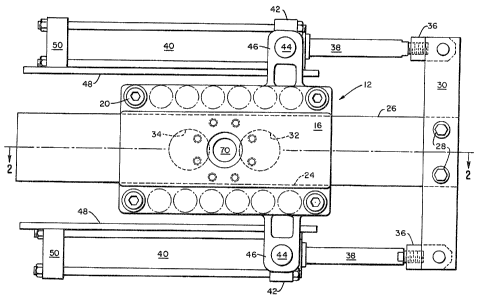
Brief Descri~ n of th~ Drawinq
Fig. 1 is an elevation of a preferred
embodiment of polymer filtration apparatus according
to this invention, taken transversely of the general
5 flow path o~ polymer through the apparatus.
Fig. 2 is a plan vi~w in section taken on
line 2-2 of Fig. 1, showing t:he two filter scre2ns in
their normal active position~;.
Fi~. 3 is a plan view similar to Fig. 2,
10 showing the slide member in a ~change positionU for
replacing one of the filter screens.
Fig. 4 is a plan view similar to Figs. 2 and
3, showing the slide member in a Ubleed position~ for
prefilling and bl~eding air from a newly replaced
15 filter screen.
Fig. 5 is an elevation viewed from the
~irection of line 5-5 in Fig. 4, showing further
details of the bleed passages.
Petailed Description
Fig. 1 is an elevation showing th~ presently
preferred embodiment of polymer filtration apparatus
according to this invention. A body 12 comprises a
pair of s~ructurally rigid halves 14 and 16 ~Fig. 2),
a pair of spacer plates 18 and a plurality of tie
25 bolts 20 e~tending through flanges 22 on the halves
14 and 16, joining them with the plates 18 to form a
rigid assembly.
The plates 18 ~Fig. 2) and the body halve~
14 and 16 form a slide channel 24 of rectangular
30 cross section e~tending through the body.
~3~B~2
A slide member 26 also of rectangular cross section
is slidingly received in the channel and affi~ed by
bolts 28 to a crossbar 30. The slide member 26 has a
pair of filter apertures 32 and 34, details of which
5 are shown in Figs. 2 to 5.
~ locks 36 are swiveled on ~he crossbar 30
and are threaded into piston rods ~which
reciprocate in hydraulic cylinders 40. Heads 42 of
the cylinder~ 40 have cylindrical trunnions 44 which
10 are received in brackets 46 imtegral with or secured
to the halves 14 and 16 of the body 12. Protective
shields 48 are fi~ed to the heads 42 and caps 50 of
the cylinders 40.
Means (not shown) are provided for
15 application of hydraulic pressure to the cylinders
40, which cause the slide member 26 to reciprocate in
the channel 24, moving the slide member a suficient
distance in either direction to locate either of the
filter apertures 32 or 34 externally of the body 12.
Each of the filter apertures 32 and 34 in
the slide member 26 is a countersunk borehole having
a larger upstream diameter D and a smaller downstream
diameter D'. This forms an annular shoulder 56
(Figs. 2 and 3) on which a breaker plate 58 of
25 conventional form is received. Each breaker plate
comprises a ri~id, remova~le cylindrical body having
a plurality of thru holes 60 evenly d;stributed
throuqhout its area. Replaceable filter screens 62
and 64 are fitted against and supported by the
30 upstream faces of the breaker plates.
3L3~ 7:~
The halves 14 and 16 of the body 12 are each
formed with divided internal polymer flow passages.
The body halve 14 has an inlet 64, a first upstream
passage 66 and a second upstream passage 68, the two
5 passages communicating at one end with the inlet 64
and at the other end with the slide member channel
24. Similarly, the body halve 16 has an outlet 70, a
first downstream passage 72 and a second downstream
passage 74, the two passages communicating at one end
10 with the outlet 70 and at the other end with the
channel 24 The first upstream and downstream
passages are mutually opposed at their respective
ends communicating with the channel 24, and likewise,
the second upstream and downstream passages are
15 mutually opposed at their respective ends
communicatiny with the channel 24. Polymer flows in
the directions indicated by the arrows.
According to this invention, it is necessary
to comply with certain dimensional criteria.
20 Reerring to Fig. 3, the dimensi~on A is the minimum
surface distance or estent on the slide channel 24
between the ends of thP first and second upstream
passa~es 66 and 68. Likewise, the dimension A' is
the minimum surface dimension on the slide channel 24
25 b~tween the first and second downstream passages 72
and 74. The dimension B is the minimum distance or
estent between the e~d of aach of the upstream
passages 66 and 68 and the e~terior of the body 12;
and likewise, the ~imension B' is the minimum surface
30 distance between the end of each of the downstream
passaqes 72 and 74 and the s~terior o the body 12.
7;~:
The four followinq e~pressions define the
necessary dimensional relationships.
~1~ A < D
~2~ A' < D'
(3) B > D
(4) 8' > D~
In operation, the foregoing dimensional
relationships provide certain operational advantages
over the prior art, which are summarized as follows.
Assuming that the sliide member 26 is
initially in the normal active position illustrated
in Fi~. 2, if it is desired to replace the right-hand
screen 62, the slide member 26 is moved to the
right. If it is moved initially a distance D just
15 sufficient to remove the screen ~2 from communication
with the passag2 6S, the laft-hand screen 64 already
will have entered into communication with the passage
66, in view of expr~ssion (1). As a result, polymer
flow through the passagés 66 and 72 will not be
20 completely blocked in any position of the slide
member during the movement in this direction.
As the slide member moves further to the
right, it ultimately reaches the ~change position~
illustrated in Fig. 3, wherein the breaker plate 58
25 and screen 62 ar~ e~ternal to the body 12 and may be
removed for cleaninq and replacement. It will be
obssrved ~hat in the position of Fig. 3, the
left-hand screen 64 has a substantial portion of its
area in communication with the passages 66 and 72,
30 thus providing for continued polymer flow through
these passages.
~.3~
The magnitude of this portion is a function ~f the
dimension B' which preferably exceeds the dimension
D' by less than the minimum distance between the
apertures 32 and 34 as measured on ~he downstream
5 side of the slide member 26.
The slide member 26 is of sufficient length
that its free end is e~ternal to the body 12 in the
change position of Fig. 3, thereby providing a seal
over the full dimensions B and B', e~cept for the
10 filter apertures 32 and 34, in all positions of the
apparatus.
It will also be observed that by reason of
expressions (3~ and ~4~ there can be ~o position of
the slid~ member 26 in which a screen aperture 32 or
15 34 is in simultaneous direct fluid communication with
the polymer flow passages and the e~terior of the
body 12. This feature makes it possible to provide a
so-called ~bleed position~ of the slide member 26
following the replacement of a screen, as shown in
20 Figs. 4 and 5. In Fig. 5 the apparatus is viewed in
the direction of polymer flow. In the bleed position
of the screen 62 no part of the areas defined by the
filter dimensions D or D' is situated within either
of the adjacent flow ~ ssage~ 66 and 72 or the space
25 e~ternal to the body ~r. However, as stated above,
polymer flow continues through the passages 66 and 72
because the other s~seen 64 is then in communication
with these passages. A groove 76 is formed in the
upstream face of the slide member 26. This groove
30 connects with a substantially smaller, accurately
dimensioned metering groove 78 also ~ormed in this
upstream face.
--10--
When the screen 62 is in the po~ition illustrated in
Fi~s. 4 and 5 the grooves 76 and 7B c~mnunicate
between the upstream passage 66 and t~e filter
aperture 32. A groove 80 is also formad in the
5 upstream face Qf the slide member 26, and i~ the
illustrated position this ~roove ~ommunicates between
the filter aperture 32 and the e~terior of the body
12. Thus poly~er flows through the grooves 76 and 78
to the filter aperture 32, prefilling the screen 62,
10 the aperturss 60 in the breaker plate 58 and all
other portions of the aperture 32 communicatin~
therewith, allowing the escape of ~ir to the exterior
of the body 12 through the groove 80.
Preferably, a third yroov~ 82 is also formed
15 in the downstream ace of the slide member 26. This
groove communicates with the filter aperture 32, and
is somewhat longer than the groove 8D~ This permits
the movement of the slide member 26 a ~hort distance
to the left as viewed in Fig. 4 (to th~ right as
20 viewed in Fig. 5), to a position i~ which the groove
82 is in communication with the e~te~ior of the body
12, but the grooYe 80 is not. In this position,
polymer is forced to flow through the ~creen 62 and
apertures 60 by reason of the ~re~sure diferen~ial
25 between the two faces o the slide mem~er ~
In practice, the slide ~m~ar 26 may r~main
in the ~bleed position~ fo~ a s~bst~ial period of
time, for esample several minutes, to allow the
complete prefillin~ of the new scr~en and the
30 contiguous spaces within the screen ~2rture, wi~h
the complete exhaustion of air from such space~,
prior to shi~ting the scre~n 62 i~to its normal
active position communicat;ng between the upstream
and downstream pas~ayes ~ and 72.
The structure of the slide member 26 is
symmetrical with respect to the provision of
additional grooves corresponding to the grooves 76,
78, 80 and 82 for the screen 64. If desired, other
5 passages may be provided for prefilling the screens
in the bleed position and bleeding air therefrom.
These may include passages in the body halves 14 and
16 which communicate with the polymer flow passages,
the slide channel and the filter apertures 32 and 34
10 as well as with the exterior of the body 12. Such
passages may have means such as threaded screws
accessible on the e~terior of the body 12 for
selectively opening or blocking su~h passages, or
closing them to an adjustable e~tent for controlling
15 or metering the rate of flow of air and pol~mer into
and through the spaces as described~ In the
preferred arrangement shown the groove 78, haviny the
most restricted cross section, determines the rate of
flow of prefilling polymer, and its dimensions are
20 predetermined primarily by the characteristics of the
polymer and the time required for complete prefilling
and air e~haustion.
It will be observed that polymer filtration
apparatus according to this invention is so
25 constructed that the slide member 26 provides a seal
between the flow passages and the e~terior of the
body 12 ~or all positio~s of the slide member between
the normal active position and either of the
positions or changing a filter, escept that in the
30 ~bleed positions" controlled communication between
these passages and the e~terior is provided through
the metering grooves 78, and is limited by the
dimensions of these grooves and the time period
during which the slide member remains in these
35 positions~
t;i~
-12-
These parameters are easily controlled so that the
desired prefilling and air bleeding functions may be
performed over a significant period of t;me, ensuring
that all air will be e~hausted from the screen
5 apertures befor~ the screens are inserted in their
normal active positions.
.