Note : Les descriptions sont présentées dans la langue officielle dans laquelle elles ont été soumises.
~ 3 ~
WH-7408-88 . 1 . 1465H/0062F
TITLE: EAVESTROUGH HANGER
FIELD OF THE INVENTION
The presen-t invention relates to eavestroughing
systems and, particularly, eavestroughing systems where the
hooks for hanging of the eavestrough are hidden.
A number of eavestroucgh systems are now known which
use what is referred to as a hi.dden hook for suspending of
the eavestrough below the roof eave. Examples of such
systems can be appreciated from the following references:
United States Patent 4,581,857, United S-tates Patent
4,632,342 and United States Patent 3,022,029.
An eavestrough system is also known according to
United States Patent 4,257,716 and United States Patent
4,553,356 which use an eavestrough of an outer configuration
similar to that disclosed in the present application,
however, the eavestrough of these patents use a hook which
is designed to be placed about the exterior of the
eavestrough.
The following Canadian patents also disclose prior
art eavestroughing systems: 1,194,672, 1,071,377, 834,590
and 956,775.
SUMMARY OF THE INVENTION
An eavestrough, according to the present invention,
is of an extruded plastic and comprises a generally
symmetrical cross section with a flat base having outwardly
angled walls either side of the base with a vertical section
secured to each outwardly angled wall at the upper edge of
these walls. The vertical section to each side of the
eavestrough includes inwardly directed locking flanges below
an upper edge of the vertical section. Each flange at a
free end thereof includes one part of a two-part locking
arrangement by means of which the eavestrough may be
suspended.
`~
' '
~ 3 ~ 7
WH-7408-88 . 2 . 1465H/0062F
According to an aspect of the invention, the
eavestrough includes a downwardly directed lip forming one
part of the locking arrangement on each locking flange which
are used to assist in locking of the eavestrough in a
suitable eavestrough hanger.
According to a further aspect of the invention, the
flange and the associated vertical section cooperate to
provide an 'L' shaped ledge about the flange. This 'L'
shaped flange is used to provide an abutment like support
for receiving an eavestrough accessory or one edge of an
eavestrough accessory, such as a leaf guard.
According to yet a further aspect of the invention,
the eavestrough is fully symmetrical eikher side of the base
and can be installed in either orientation.
An eavestrough hanger, according to the present
invention, comprises a cored base and a forwardly extending
cantilevered arm extending from the base. The arm is of an
inverted 'T' shape in cross section and includes a front
opening locking slot at a free end of the arm. An opposite
2û opening slot is provided at the lower edge of the arm spaced
from, but adjacent the base. The base and the arm join at a
flange perpendicular to the inverted 'T' shaped section and
generally centered thereon. This flange closes the inverted
'T' section at one end of the arm and is used to assist in
securing of the arm to the base.
According to an aspect of the invention, the hanger
includes a rectangular extension joining the flange and the
base.
According to a further aspect of the invention, the
3û eavestrough hanger is adapted with the base extending above
the inverted 'T' shaped section and including in this
extension portion a securing port therein for fastening of
the hanger.
According to a further aspect of the invention, the
eavestrough hanger is adapted by including a forwardly
~ 3 ~ 7
WH-7408-88 . 3 . 1465H/0062F
opening slot in the base, across the base intermediate the
inverted 'T' shaped section and the securing port.
BRIEF DESCRIPTION OF THE DRAWINGS
Preferred embodiments of the inven-tion are shown in
the drawings, wherein:
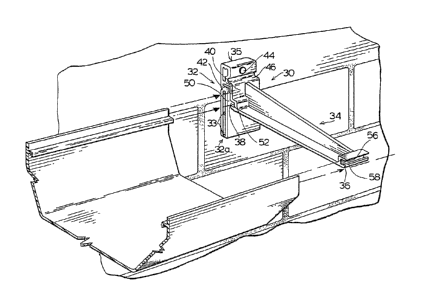
Figure 1 is a partial perspective view showing one
hanger and a portion of a building to which the hanger and
eavestrough have been secured;
Figure 2 is a partial perspective view illustrating
how the eavestrough section can slide within a hanger; and
Figure 3 is a side view showing the securement of
the eavestrough section in the eavestrough hanger.
DETAILED DESCRIPTION OF THE PREFERRED EMBûDI~ENTS
The eavestrough section 2 is preferably of a
symmetrical section having agéneral1y flat base 4 and outwardly
angled walls 6, each of which termina-te in a short vertical
section 8. The vertical sections 8 each include a locking
flange 10 having a downwardly directed lip 12 at the free
end of the locking flange. This downwardly directed lip
will cooperate with the locking slots provided in the
eavestrough hanger. Above the upper surface of each locking
flange 10 and the inside wall of the associated vertical
section 8, is an 'L' shaped ledge 14. This ledge can be
used for restraining one side of a ]eaf guard while also
serving to further hide the hook.
The eavestrough hanger 30 has a cored base 32 which
is essentially a rectangular box with certain interior
partitions and open at the sides. The hanger 30 includes a
forwardly extending cantilevered arm 34 of an inverted 'T'
shaped section. This arm 34 at the free end thereof ?
includes a front opening slot 36 for receiving one of the
locking flanges 10 by means of which the eavestrough is
partially hung below the eavestrough hanger 30. Front
opening slot 36 includes an angled camming surface 56 and a
~ 3 ~ 7
~H-7408-88 . 4 ~ 1465H/0062F
lip 58 sized to provide an interference fit with the locking
flange 10 and the downwardly dlrected lip 12. This type of
interference fit is shown in Figure 3 and the eavestrough
section may be forced as indicated by arrow 60 into the
front opening slot 36. There is a similar jam type fit
provided at the opposite opening slot 38 provided at the
lower edge of the arm 34, but spaced from the base 32.
Again, the eavestrough is forced through a slot, in this
case through slot 389 such that the vertical section extends
into the upwardly extending portion 50 of slot 38, which is
eventually limited by the rectangular section 42 with the
appropriate locking flange located in the horizontal
extending portion 52 of slot 38. This horizontal extending
portion 52 includes a lip 54 at the entrance thereof to
provide a lock with the cooperating lip 12 of the locking
flange 10. These parts cooperate to provide a two-part
interference locking arrangement.
The front opening locking slot 36 and the opposite
opening slot 38 are sized to allow free movement of the
eavestrough section within the slots to accommodate
longitudinal expansion of the eavestrough section, however,
the eavestrough is firmly locked within each slot due to the
cooperation of the locking flanges 10 and slots 36 and 38.
The cored base 32 extends above the cantilevered
arm 34 and defines in an upper region a securing port 44
through which a screw may be inserted to effect securement
of the eavestrough hanger. The hanger also includes
alignment recesses 60 provided at the rear surface of the
base which are used in properly placing the eavestrough
hanger the required distance below the eave of the roof.
For example, a line could be drawn on the fascia board, with
this line appropriately sloped according to the
requirements, and then the eavestrough hangers are located
on the fascia board with the aid of alignment recesses 60
being placed on that line. In this way, each of the hangers
~ 3 ~ 7
WH-7408-88 . 5 . 1465H/0062F
will ensure that the eavestrough is properly sloped -to drain
in a predetermined manner.
Both the eavestrough 2 and the eavestrough hanger
30 are made of a suitable ultraviolet stabilized plastic
material, as is known in the art.
The particular eavestrough hanger 30, and the
manner of coring the same, ensures there are minimal
problems due to shrinkage of material during cooling of the
hanger after the injection molciing thereof. The various
cavities are interconnected by partitions to add structural
integrity and each of the cavities terminate generally at a
vertical plane through the base, centered on the base, such
that there is a solid core of plastic extending from the
rear of the base into the forwardly extending arm and
therebelow. This vertical reinforcing adjacent the arm
increases the strength of the hanger. The forwardly
extending cantilevered arm 34 terminates at the flange 40
which is generally perpendicular to the 'Tl shaped section
of arm 34. This flange is the same size as the base and
stiffens the arm and provides effective load transfer
between the arm 34 and the forwardly extending rectangular
section 42. This forwardly extending section 42 is cored,
however, rather than being vertically cored, it is cored in
a generally horizontal manner to increase the structural
strength thereof.
The cored base 32 of the eavestrough hanger 30 has
a lower elongate box-like section 32a with a number of
reinforcing partitions 33 extending therethrough. This
elongate box-like section increases the stiffness of this
lower base portion and thus stiffens the relationship
between the lower portion of the forwardly extending arm and
the base. The cored box-like area 35 provided above the
forwardly extending rectangular section 42 a].so provides
additional stiffening and this stiffening is reinforced by
the bushing about the securing port 44. By coring of the
base to provide a backwall and a forward wall,
~31~
WH-7408-88 . 6 . 1465H/0062F
interconnec-ted by a central partition running generally
vertically and various horizontal partititions, less
material is required and the configuration provides
additional strength.
In molding of hangers of this type, there is
difficulty in just adding more material, as after molding,
shrinkage can cause distortion and flaws in the hanger.
Thus, by coring the hanger in the manner described and
configuring it, the benefits in reduction of material are
lû achieved while still providing a rigid configuration. Also,
the molding of this article allows various configurations to
be used, for example, the forwardly extending section 42 is
perpendicular to the cored lower elongate box-like section
32a while the material is integral as the product has been
mo]ded. This overlapping relationship of the various cored
areas results in a strong base portion which also allows
effective connection of the forwardly extending cantilevered
arm 34 with the base.
When load is applied to the hanger by the
eavestrough, it is opposed by the screw which is passed
through securing port 44 and it is also opposed by the lower
elongate box-like section 32a which will contact the facia
and distribute the load thereto. As can be appreciated, the
hanger or the forces on the hanger will tend to be
downwardly directed causing a moment generally about the
facia board and this is partially opposed by the reaction
force acting on lower elongate box-like section 32a.
Therefore, this section must be stiff but also the
connection of this section to the upper cored area 35 must
also be stiff. Similarly, it is important that the
- connection of the arm to the base is as stiff as possible to
avoid flexing of the structure.
The strength of the arm is further improved by the
flange 40 which is in a stepped wall configuration to
partially define a locking slot while also connecting the
lower flange o-f the forwardly extending cantilevered arm 34.
'7
WH-7408-88 . 7 . 1465H/0062F
In effect, the base is of a cellular type structure which
not only allows convenient molding thereof, but also
positions the material of the base in a configuration to
improve the structural integrity of the base while allowing
effective connection of the forwardly extending cantilevered
arm to the base by means of the forwardly extending
rectangular bridge section 42. Thus, the present design
recognizes the need to not only limit the material used in
the hanger, but to position this material in a manner to
avoid problems often caused by shrinkage during cooling of
the product after molding while effectively posltioning the
material to improve the strength of the resulting structure.
The eavestroughing system, according to the present
invention, uses a force fit of the eavestrough section into
the hanger, avoiding problems which can occur when spring
deformation is associated with the locking. Plastic
typically creeps during heat and a spring bias type
arrangement for locking does not provide the same structural
strength as a locking interfit, where problems associated
with creep are reduced. Furthermore~ this positive locking
of the eavestrough within the eavestrough hanger avoids
problems which can occur due to improper loading such as by
placing a ladder on the eavestrough section. Such a load
would tend to increase the securement of the locking flange
within the forwardly opening slot 36 while the slot provides
some support against buckling. The vertical section of the
wall also strikes the end of the arm and further distributes
the load.
An eavestrough under normal operating conditions is
not subject to particularly high loads, however, it is
subject to extreme temperature ranges from the coldest day
in winter to the hottest day in summer and is also subject
to ice loads and must at least withstand these loads which
can greatly exceed the actual volume of the eavestrough.
Although various preferred embodiments of the
present invention have been described herein in detail, it
:
WH-7408-88 . 8 . 1465H/0062F
will be appreciated by those skilled in the art, that
variations may be made thereto without departing from the
spirit of the invention or the scope of the appended claims.
.