Note : Les descriptions sont présentées dans la langue officielle dans laquelle elles ont été soumises.
"`` ` I 3 1 2579
~ lICl~ SDI~ABLE FO~ ~SE AS A DUAL-CHA~E$~ED CAN
The present invention relates to a device suitable for use as a
dual chambered can
Such a device is known from German Patent 21 49 569. Such cans
are widely used by forest workers who operate chain saws powered
by two-stroke engines. In practice, the two-stroke mixture is
stored in the larger 5 litre chamber, while the smaller 2.5 litre
chamber contains the chain lubricant. Clearly, this type of can
can have many other use~. ~he disadvantage~ of this
construction, which dates ~rom 197~, are the following:
1. The thickness of connecting member 28 is so~ewhat less
than doubl~ the thickness of the material used in
construction, i.e, 5mm. Such meagre dimensions do not
provide the thickness required to separate both
chambers. It must also be remembered that such cans,
being produced by the blow-mold process, are rather
less solidly constructed than injection-molded
containers.
2. In order to remedy the instability of the connecting
member, handle 3 was provided with root~, of which the
fist was a~fixed to the larger chamber, the second to
the larger and smaller chambers and the third solely
to the smaller chamber. This arrangement wastes
.,, ,~
S,
2 131~57~
material, since one need use only the handle that is
situated over the centre of gravity~
3. Blow molding of this handle str~cture requires
advanced techniques and relatively complicated blowing
molds.
4. The above-mentioned second handle raot limits the
~inger opening in the handle to a relatively small
size, to the detriment of the user attempting to grasp
the can, particularly if gloves are worn. There
exists i~ Canada, ~or instance, a polar glove
fashioned without individual finger poalcets; such a
glove could not possibly ~it through a handle opening
of this size.
5. The handle, also being blo~-molded, features a cavity.
~: Were no constriction point made in the handle, the
contents of the smaller chamber could be permitted to
mix with the contents of the larger chamber, which
would be inappropriate. The existence of such a
constriction point would also weaken the handle, given
2~ the premise that a pipe composed of a given ~uantity
o~ material would exhibit the greatest strength i~ its
load bearing capacity were uncompromised in all
directions.
!
3 ~ 3 1 2579
6. It is not possible in this case to use the handle
cavity for returning, during pouring, air to t~e rear
of the larger chamber.
7~ The rectilinear construction of the connecting member
i~poses at least upon the smaller chambar a somewhat
flat rectangular shape, which hals not proved to be
especially resistant in impact tests.
The object o~ the present invention is to identi~y a means of
retaining the dual-chamber principle while simplifying the method
of connecting the smaller chamber to the larger chamber.
In a broad aspect, the present invention relates to a device
suita~le for use as a one-piece dual-chambered can o~ blow-
molding synthetic material said devic~ haviny a larger chamber
~or holding gasoline, a smaller chamber f~r holding oil~ a
separation plane between said chambers, a thin connecting member
arranged between said chambers in said separation plane and
forming part of said chambers, an upper side on said larger
chamber and a handle straddling said separation plane, said
handle having a handle root that begins on ~aid upper side o~
said larger chamber, wherein; (a) said c~nnacting member is
arranged outside o~ said handle; ~h) said smaller cha~ber has an
upper zone that extends cupola-like at least pa~tway up the
height o~ said handle; (c) said handle has 2 second handle root
havin~ a bulge that extends very close to said upper cupola-like
zone of said ~maller chamber; (d) said second handle root emerges
1 3 1 2579
from said upper side of said larger chamber adjacent said upper
cupola-like ~one of said s~aller ch~mber; (e~ said device has a
floor zone on both of said chambers, and viewed from the side,
said connecting memb~r desaribes a curve from said floor zone to
a zone situated between said second handle root and said upper
cupola-like zone of said smaller chamber; (~) fiaid curve
~omprises a first longer section that extends upward from said
floor zone and a second shorter section that rises at a bend
between said first and second sections to form an obtuse angle
with said first section; and ~g) said second handle root is
considerably thicker in the zone of said second section than said
first handle root, and said second handle root protrudes in the
manner o~ a chin over said smaller chamber and tnen curves
inwardly.
The nonlinearity of the connecting member has been welded to the
cupola shape of the upper zone of the smaller chamber to provide
impact resistance in the event oE dropping. The handle is
solidly joined to the connecting member, even at the point where
the two chambers are no longer joined together. Such a shape
furthermore facilitat~s the arran~ement of a handle having a
large grip opening. The shape of the connecting member, being
bowed and dome-like, affords resistance against dropping and gas
pressure buildup. Also, the production of the thin blow-molded
wall and the subsequent cold drilling of the holes therein has
been facilitated by the present invention. This procedure would
not be as simple were the connecting member bent throughout.
1312579
Furthermore, the second handle root is bett~r to absorb the
forces transferred to it from the connecting member. This
condition, which applies especially to the upper cupola-shaped
zone of the smaller chamber, also permits the second handle root
to absor~ the force of blows upon it.
Furthermore, in the present invention, there are uninterrupted
points of contact between the two containers, which improves
production, optimizes wall thickness, enhances load bearing
capacity etc.
The present invention shall next be described in greater detail
by means of drawings of a preferred embodiment thereo~. Shown
are:
Figure 1 ~- a side view of the proposed can;
Figure 2 -- a view as indicated by arrow 2 of Figure l;
Figure 3 -- a view as indicated by arrow 3 of Figure l;
Figure 4 -- a view as indicated by arrow 4 of Figure l;
Figure S -- a view as indicated by arrow 5 of Figure, 1.
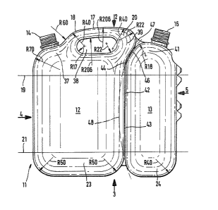
A dual-chambered can 11 is blow-molded from a synthetic material.
The larger of its two chambers 12 holds 5 litres of li~uidl
whereas the smaller chamber 13 holds 2.5 litres. ~he larger
chamber 12 possesses, in accordance with Figure 1, a le~t-~acing,
integrally-produced threaded neck 14, and the smaller chamber has
a right facing integrally-produced threaded neck 16.
1312579
-6-
Emerging from the upper side of chamber 12 is a handle 17, having
in the zone near threaded neck ~4 a smaller handle root 18, as well
as a larger handle root 20. The wall thickness of the synthetic
material lies between 3 and 4 mm. The section of wall located
between lines 19 and 21 is, with the exception of the bowed-out
portions 22 (which shall not concern us here) -- in th~ form of a
straight line that runs parallel to the datum plane of Figure 1, -
or, rather, perpendicular to the surface upon which the dual
chambered can 11 naturally sits.
Chamber 12 exhibits below line 21, the ~orm of a ~latj downwardly-
oriented support dome 23 featuring large radii. Support dome 24
of the smaller chamber ~3 also features large radii. ~he radii,
in both cases, extend to the oval support surface 26 of the larger
chamber 12 and up to the more rectangular support surface 27 of the
smaller chamber 13.
As Fig. 3 in particular demonstrates, the outline of smaller
chamber 12 is rectangular with highly rounded corners, whereas
larger chamber 13 is in this view elongated rectangular/oval with
well-rounded corner radii. Such radii are in this respect larger
in the larger chamber 12 than the corresponding radii of the
smaller chamber 13, which prevents the vapour pressure developing
in chamber 12 from significantly changing the basic shape of the
can. The individual radii are shown in the drawing.
1 31 2579
--7--
The central zone of the support surfaces, represented by 8 and 29
is depressed inwardly, in order to prevent the bottom of the can
from resting directly on the ground, if the latter is fairly even.
The central zones of the can bottom 28, 29/ are reinforced either
by wide cross members 31 or by one cross member 32. To the left
and right of a medial plane of symmetry, cross members 31 and 32
are intersected by longitudinal members 34, 36 whose width is equal
to that of such cross members. Chamber 12 rises above line 19 to
merge into a large-radius cupola 37, which curves upward to the
left to support threaded neck 14. The first handle root 18, which
begins a short distance to the right of threaded neck 14, i5
considerably narrower than khe width o~ threaded neck 14, maintains
this cross section alony practically the entire length of handle
opening 38, and then widens so that the width of the second handle
root 20 exceeds the practically 40mm diameter of threaded neck 16.
As Fig. 1 illustrates, handle root 20 extends to the right with a
protuding chin 39 into a zone that partially ovPrlaps chamber 13.
Two thirds of the length of handle 17 lying to the right-hand side
has a shape not unlike that of a saxophone. Handle opening 38 is
large enough to accomodate winter gloves. The middle of handle
17 sits more or less over the common centre of gravity of dual-
chambered can 11, when both chambers 12 and 13 are filled with
liquid.
Chamber 13 rises above line 19 to form a cupola 41 having very
:`
1312579
large radii and supporting threaded neck 16. The left-hand 20ne
of cupola 41 follows the under-contour of chin 39.
Chambers 12 and 13 are joined together by means of a connectin~
member 42 that is approximately 5 mm thick and comprises a first
linear section 43 that begins a short distance below line 21 and
follows perpendicular madial plane of symmetry 33 to the top. The
thickness of linear section 43 -- like the entire connscting
member 42, 3-4 mm -- merges at a 45 bend 44 into a shorter linear
section 46 that iB basically equal in length to the underside o~
chin 39. Because cupola 41 con~orms closely to chin 39, se~tion
46 has only to be a few millimeters thick. Component 46 merges at
the top into a delta 47, resembling a small fishtail.
The non-linearity of connecting member 42 does not necessarily have
to be produced in the manner described in the embodiment example
given. In the example described, the ratio o~ long sections to
short sections would be about 4:7. This ratio could vary upwardly
or downwardly by 10%.
The non-linearity of connecting member 42 can also be achieved by
bending connecting member 42 into an arc as indicated by the dotted
line 48.