Sélection de la langue

Search

Sommaire du brevet 1315175 

Énoncé de désistement de responsabilité concernant l'information provenant de tiers

Une partie des informations de ce site Web a été fournie par des sources externes. Le gouvernement du Canada n'assume aucune responsabilité concernant la précision, l'actualité ou la fiabilité des informations fournies par les sources externes. Les utilisateurs qui désirent employer cette information devraient consulter directement la source des informations. Le contenu fourni par les sources externes n'est pas assujetti aux exigences sur les langues officielles, la protection des renseignements personnels et l'accessibilité.

Disponibilité de l'Abrégé et des Revendications

L'apparition de différences dans le texte et l'image des Revendications et de l'Abrégé dépend du moment auquel le document est publié. Les textes des Revendications et de l'Abrégé sont affichés :

  • lorsque la demande peut être examinée par le public;
  • lorsque le brevet est émis (délivrance).
(12) Brevet: (11) CA 1315175
(21) Numéro de la demande: 608922
(54) Titre français: CLAPET DE FERMETURE AUTOMATIQUE DE ROBINET
(54) Titre anglais: AUTOMATIC FLUID FLOW SHUT-OFF DEVICE
Statut: Périmé
Données bibliographiques
(52) Classification canadienne des brevets (CCB):
  • 137/63
(51) Classification internationale des brevets (CIB):
  • F16K 17/28 (2006.01)
  • F16K 17/24 (2006.01)
  • F16K 17/36 (2006.01)
  • F17C 13/12 (2006.01)
(72) Inventeurs :
  • FOSTER, GEOFFREY FREDERICK (Australie)
(73) Titulaires :
  • PREMIER-FOSTERS (AUSTRALIA) LIMITED (Australie)
(71) Demandeurs :
(74) Agent: SMART & BIGGAR
(74) Co-agent:
(45) Délivré: 1993-03-30
(22) Date de dépôt: 1989-08-21
Licence disponible: S.O.
(25) Langue des documents déposés: Anglais

Traité de coopération en matière de brevets (PCT): Non

(30) Données de priorité de la demande:
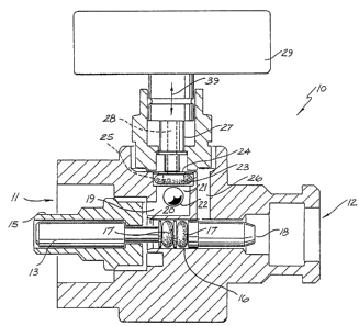
Numéro de la demande Pays / territoire Date
PI9968 Australie 1988-08-19

Abrégés

Abrégé anglais


ABSTRACT
A gas shut-off device 10 for a gas cylinder, to stop gas flow from
the cylinder if the gas flow becomes excessively high, or the device is
tilted from its normal orientation. The device 10 includes a cylindrical
chamber 21 having a gas inlet 20 and a gas outlet 25, with a ball 22
located within the chamber 21 to close the outlet 25 if the gas flow
becomes excessively high or the device 10 becomes tilted.

Revendications

Note : Les revendications sont présentées dans la langue officielle dans laquelle elles ont été soumises.


-4-
The embodiments of the invention in which an exclusive property
or privilege is claimed are defined as follows:
1. A fluid flow shut-off device comprising:
a hollow body having an inlet connection portion to be connected to a
supply of fluid under pressure, and an outlet connection portion to be
connected to an apparatus to receive said fluid, said body providing a
chamber through which the fluid passes from a chamber inlet to a chamber
outlet, said inlet and outlet being positioned so that fluid entering said
chamber enters in a direction having a direction component normal to the
direction of the fluid entering said outlet, with said outlet being
positioned at an upper portion of said chamber when said device is in its
normal operating orientation having said inlet generally horizontally
facing;
a movable valve ball captively located within said chamber to
selectively engage said outlet to prevent fluid flow therethrough, wherein
said ball will engage said outlet when either the fluid flow rate becomes
excessively high through said device or said device is tilted through a
predetermined angle from its normal operating orientation.
2. The fluid flow shut-off device of claim 1, wherein said outlet
is generally downwardly facing and said chamber is of a cylindrical
configuration, with the longitudinal axis thereof vertically oriented
during normal operation.
3. The fluid flow shut-off device of claim 2, wherein said outlet
is provided with a resilient ring against which said ball engages.
4. The fluid flow shut-off device of claim 3, wherein said inlet
connection portion and said outlet connection portion are horizontally
aligned along a common axis, and the longitudinal axis of said chamber
extends generally radially from said common axis.
5. The fluid flow shut-off device of claim 4, further including a
valve actuator extending from said outlet connection portion to said inlet

- 5 -
connection portion to operate a valve of said supply upon said outlet
connection portion being connected to said apparatus.
6. The fluid flow shut-off device of claim 5, further including a
hollow shaft slided mounted within said body for connection to a pressure
measuring gauge which hollow shaft is movable from a retracted position
clear of said outlet, and a reset position protruding through said outlet
to dislodge said ball.
7. The fluid flow shut-off device of claim 6, wherein said body has
a passage extending along said common axis, which passage receives said
valve actuator, which passage is sealingly divided between a downstream
portion located in said inlet connection portion, and an upstream portion
located in said outlet connection portion.
8. The fluid flow shut-off device of claim 7, wherein said outlet
communicates with said upstream portion, and said downstream portion
communicates with said inlet.
9. The fluid flow shut-off device of claim 2, wherein the ratio of
the ball diameter to the chamber diameter is about .7, and said ball is
formed of steel.
10. The fluid flow shut-off device of claim 2, wherein said ball has
a weight of about 4.3gm and a diameter of about 4.8mm, and said chamber has
a diameter of about 6.6mm.
11. The fluid flow shut-off device of claim 2, wherein said ball has
a weight of about 4.9gm and a diameter of about 5.4mm, and said chamber has
a diameter of about 7.5mm.

Description

Note : Les descriptions sont présentées dans la langue officielle dans laquelle elles ont été soumises.


1 3 ~

62616-105
Background of the Inven~ion
The present invention relates to fluid flow shut-off
devices and in particular to an emergency, automatic shut-off
device for gas cylinder operation.
Discussion of Prior Art
An automatic fluid flow shut-off device is known in
which a ball moves into engagement with a seat to prevent gas flow
in emergencies. However, it can not be guaranteed that the device
will operate in all circumstances, particularly if the device is
incorrectly oriented relative to the horizontal.
German Specification 2249598 describes a ball valve
which is operated if the gas flow becomes excessive. The valve is
intended to be operated so that the valve is accelerated upwardly
against the force of gravity when the gas flow becomes excessive.
There is no consideration given to providing this valve with a
shut-off function if it becomes incorrectly oriented. Still
further, the various embodiments of this particular device shown
and dlscussed, do not lend themselves to actuation if the device
is merely tilted.
Objects and Summary of the Invention
It is the object of the present invention to overcome or
substantially ameliorate the above disadvantage.
There is disclosed herein a fluid flow shut-off device
comprising:
a hollow body having an inlet connection portion to be
connected to a supply of fluid under pressure, and an outlet
connection portion to be connected to an apparatus to receive said
fluid, said body providing a chamber through which the fluid
passes from a chamber inlet to a chamber outlet, said inlet and
outlet being positioned so that fluid entering said chamber enters
in a direction having a direction component normal to the


, 1

~ 3~ ~7 ~ ~

-- 2 --
direction of the fluid entering said outlet, w~th said outlet being
positioned at an upper portion of said chamber whell said device is in its
norma7 operating orientation having said inlet generally horizontally
fac~ng;
a movable valve ball captively located within said chamber to
selectively engage said outlet to prevent fluid flow therethrough, wherein
said ball will engage said outlet when either the fluid flow rate becomes
excessively high through said device or said device is tilted through a
predetermined angle from its normal operating orientation.
Brief Description of the Drawing
A preferred form of the present invention will now be described by
way of example with reference to the accompanying drawing, which
schematically depicts in sectioned side elevation a fluid flow shut-off
device.
Description of the Preferred Embodiment
In the accompanying drawing there is schematically depicted a fluid
flow shut-off device 10. The device 10 is connectable to a gas cylinder
(not shown) at the inlet end 11. The connection being any convenient means
such as snap-on, push-on or screw threaded, connection. At its other end,
outlet end 12 is adapted to be connected to a regulator (not shown).
The device 10 has a shaft 13 located in a body 15 adapted to abut a
needle valve of the gas cylinder.
The body 15 has a further passage 16 sealingly engaged by O-rings 17
mounted on the shaft 13. The shaft 13 extends to a leading portion 18.
When connected to the regulator, the leading portion 18 is engaged and the
shaft 13 moved to operate the needle valve of the gas cylinder. The O-rings
17 divide the passage 16 into an upstream and a downstream position.
The passage 15 communicates with a chamber 19 having an inlet chamber
portion 20 and an outlet chamber portion 21. Located in the outlet chamber

~ ~ 3 5 ~ 7 ~

portion 21 is a ball 22. The chamber portion 21 is of a cylindrical
configuration, having its axis normal to the axis of the passage 16.
The chamber portion 21 is provided with an 0-ring 23 against which a
washer 24 bears. The 0-ring 23 and washer 24 provide an outlet passage 25.
The outlet passage 25 is of a smaller cross sectional area than the ball
22, so that upon the ball 22 seating against the 0-ring 23, fluid flow is
prevented.
Fluid leaving the passage 24 passes through the washer 24 via the
passage 25 to an outlet passage 26 to be delivered to the outlet end 12.
It should be appreciated that fluid entering the chamber 21, from the
chamber 20, has a direction of travel at least partly normal to the
direction of travel of fluid entering the passage 25. By providing this
configuration, the device 10, if inadvertently tilted or moved, independent
of the starting orientation, will act to stop gas flow by engagement of the
ball 22 with the 0-ring 23. This will also occur when there is excessively
high gas speeds.
Also mounted in the body 15 is a hollow shaft 27 having a central
passage 28 extending to the passage 25. The passage 28 communicates with a
pressure gauge 29. Still further, the shaft 27 is movable in the direction
of the arrow 39 so that movement of the shaft 27 can move the ball 22 from
engagement with the 0-ring 23 in order to reset the devlce 10.
~ here a steel ball 22 is employed, it has been found that the ratio
of the ball diameter to the diameter of the chamber 21 is.approximately .7.
It has also been found that the ball 22 if provided with a weight of
about 4.3 gm (about 4.8 mm diameter) co-operates with a chamber 21 diameter
of 6.60 mm. As a further alternative, a ball 22 having a weight of 4.871
gm (5.40 mm diameter) co-operates with a chamber 21 diameter of 7.50 mm.


~s

Dessin représentatif
Une figure unique qui représente un dessin illustrant l'invention.
États administratifs

Pour une meilleure compréhension de l'état de la demande ou brevet qui figure sur cette page, la rubrique Mise en garde , et les descriptions de Brevet , États administratifs , Taxes périodiques et Historique des paiements devraient être consultées.

États administratifs

Titre Date
Date de délivrance prévu 1993-03-30
(22) Dépôt 1989-08-21
(45) Délivré 1993-03-30
Expiré 2010-03-30

Historique d'abandonnement

Il n'y a pas d'historique d'abandonnement

Historique des paiements

Type de taxes Anniversaire Échéance Montant payé Date payée
Le dépôt d'une demande de brevet 0,00 $ 1989-08-21
Enregistrement de documents 0,00 $ 1990-01-19
Taxe de maintien en état - brevet - ancienne loi 2 1995-03-30 50,00 $ 1995-03-24
Taxe de maintien en état - brevet - ancienne loi 3 1996-04-01 250,00 $ 1996-07-25
Taxe de maintien en état - brevet - ancienne loi 4 1997-04-01 50,00 $ 1996-11-28
Taxe de maintien en état - brevet - ancienne loi 5 1998-03-30 75,00 $ 1998-02-06
Taxe de maintien en état - brevet - ancienne loi 6 1999-03-30 150,00 $ 1999-01-25
Taxe de maintien en état - brevet - ancienne loi 7 2000-03-30 150,00 $ 2000-02-14
Taxe de maintien en état - brevet - ancienne loi 8 2001-03-30 350,00 $ 2001-06-21
Taxe de maintien en état - brevet - ancienne loi 9 2002-04-01 75,00 $ 2002-02-18
Taxe de maintien en état - brevet - ancienne loi 10 2003-03-31 100,00 $ 2003-02-18
Taxe de maintien en état - brevet - ancienne loi 11 2004-03-30 250,00 $ 2004-02-18
Paiement des arriérés de taxes 125,00 $ 2005-02-08
Taxe de maintien en état - brevet - ancienne loi 12 2005-03-30 125,00 $ 2005-02-08
Paiement des arriérés de taxes 125,00 $ 2006-02-07
Taxe de maintien en état - brevet - ancienne loi 13 2006-03-30 125,00 $ 2006-02-07
Paiement des arriérés de taxes 125,00 $ 2007-02-08
Taxe de maintien en état - brevet - ancienne loi 14 2007-03-30 125,00 $ 2007-02-08
Taxe de maintien en état - brevet - ancienne loi 15 2008-03-31 450,00 $ 2008-02-08
Taxe de maintien en état - brevet - ancienne loi 16 2009-03-30 450,00 $ 2009-02-12
Titulaires au dossier

Les titulaires actuels et antérieures au dossier sont affichés en ordre alphabétique.

Titulaires actuels au dossier
PREMIER-FOSTERS (AUSTRALIA) LIMITED
Titulaires antérieures au dossier
FOSTER, GEOFFREY FREDERICK
Les propriétaires antérieurs qui ne figurent pas dans la liste des « Propriétaires au dossier » apparaîtront dans d'autres documents au dossier.
Documents

Pour visionner les fichiers sélectionnés, entrer le code reCAPTCHA :


Pour visualiser une image, cliquer sur un lien dans la colonne description du document. Pour télécharger l'image (les images), cliquer l'une ou plusieurs cases à cocher dans la première colonne et ensuite cliquer sur le bouton "Télécharger sélection en format PDF (archive Zip)" ou le bouton "Télécharger sélection (en un fichier PDF fusionné)".

Liste des documents de brevet publiés et non publiés sur la BDBC .

Si vous avez des difficultés à accéder au contenu, veuillez communiquer avec le Centre de services à la clientèle au 1-866-997-1936, ou envoyer un courriel au Centre de service à la clientèle de l'OPIC.


Description du
Document 
Date
(yyyy-mm-dd) 
Nombre de pages   Taille de l'image (Ko) 
Dessins 1993-11-10 1 23
Revendications 1993-11-10 2 73
Abrégé 1993-11-10 1 12
Page couverture 1993-11-10 1 12
Description 1993-11-10 3 121
Dessins représentatifs 2001-07-31 1 16
Taxes 1999-01-25 1 45
Correspondance 1998-06-09 1 13
Taxes 2001-06-21 1 31
Lettre du bureau 1989-11-21 1 59
Demande d'examen 1992-01-30 1 70
Correspondance de la poursuite 1989-11-30 1 32
Correspondance reliée au PCT 1993-01-21 2 34
Correspondance reliée au PCT 1993-01-20 1 39
Correspondance de la poursuite 1992-06-17 4 150
Correspondance de la poursuite 1989-10-19 1 39
Correspondance de la poursuite 1992-06-01 5 197
Taxes 1996-11-28 1 70
Taxes 1996-07-25 2 62